Haier HCR2250AES User manual

24"Electric Free-Standing Range
Cuisinière autoportante électrique de 24"
Estufa independiente eléctrico de 24"
Installation Instructions
Instructions d’installation
Instrucciones de instalación
HCR2250AES
HCR2250ACS
F
o
IMPORTANT: Save for local electrical inspector’s use.
IMPORTANT: Conserver pour consultation par l’inspecteur local des installations électriques.
IMPORTANTE: Guárdelo para uso del inspector eléctrico local.
Part # 0570000768 REV B


1
TABLE OF CONTENTS
RANGE SAFETY...................................................................................................1
INSTALLATION REQUIREMENTS.........................................................................2
Tools and Parts...............................................................................................................2
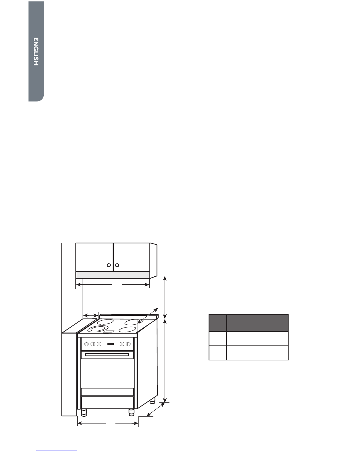
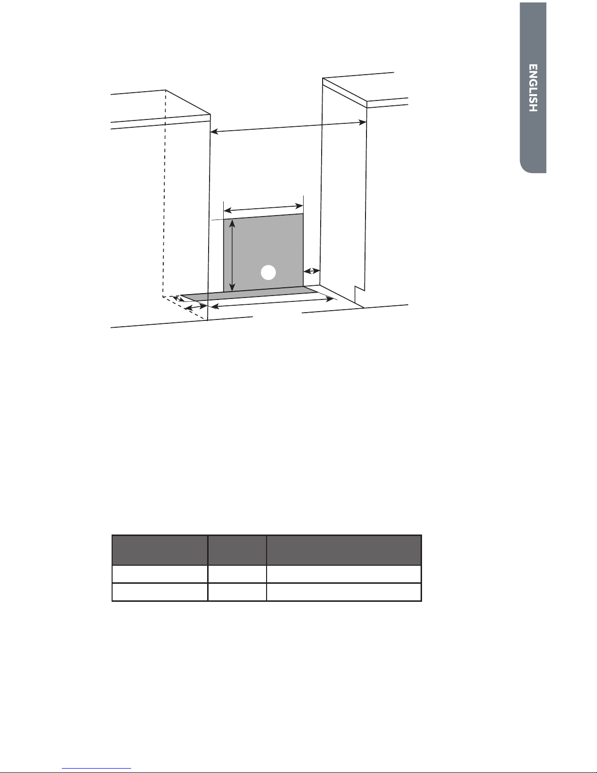
Location Requirements.................................................................................................3
Electrical Requirements ................................................................................................ 5
INSTALLATION INSTRUCTIONS..........................................................................8
Step 1 - Unpack Range ..................................................................................................8
Step 2 - Install Anti-Tip Bracket ....................................................................................9
Step 3 - Make Electrical Connection...........................................................................10
Step 4 - Install Range...................................................................................................22
Step 5 - Complete Installation ...................................................................................23
RANGE SAFETY
Your safety and the safety of others are very important.
We have provided many important safety messages in this manual and
on your appliance. Always read and obey all safety messages.
DANGER
WARNING
CAUTION
This is the safety alert symbol.
This symbol alerts you to potential hazards that can
kill or hurt you and others. All safety messages will
follow the safety alert symbol and either the word
“DANGER,” “WARNING” or “CAUTION.”
These words mean:
An imminently hazardous situation. You
could be killed or seriously injured if you
don’t immediately follow instructions.
A potentially hazardous situation
which, if not avoided, could result in
death or serious bodily injury.
A potentially hazardous situation
which, if not avoided, may result in
moderate or minor injury.
All safety messages will tell you what the potential hazard is, tell you
how to reduce the chance of injury, and tell you what can happen if the
instructions are not followed.

2
State of California Proposition 65 Warnings:
WARNING: This product contains one or more chemicals known to the
State of California to cause cancer.
WARNING: This product contains one or more chemicals known to the
State of California to cause birth defects or other reproductive harm.
WARNING
Tip Over Hazard
A child or adult can tip the range and be killed.
Connect anti-tip bracket to rear range foot.
Reconnect the anti-tip bracket, if the range is moved.
Failure to follow these instructions can result in death or serious burns
to children and adults.
INSTALLATION REQUIREMENTS
TOOLS AND PARTS
Gather the required tools and parts before starting installation. Read and follow the
instructions provided with any tools listed here.
TOOLS NEEDED
• Tape Measure
• Flat-Blade Screwdriver
• Phillips Screwdriver
• Level
• Cordless Electric Drill
• Hammer
• Wrench or Pliers
• Metal Saw
• Metal Snips or Large Wire Cutters
•
•
•
•
• Marker or Pencil
• Masking Tape

3
PARTS SUPPLIED
Check that all parts are included.
a
b
a
b Anti-tip Bracket
NOTE:
Longer screws are available from your local hardware store.
PARTS NEEDED
If using a power supply cord:
• A UL listed power supply cord kit marked for use with ranges. The cord should
be rated at 250 volts minimum, 40 amps or 50 amps that is marked for use
terminals or open-end spade terminals with upturned ends.
• A UL listed strain relief.
If direct wiring:
• Flexible Metal Conduit
• UL Listed Conduit Connector
•
• UL Listed Wire Connectors
Check local codes. Check existing electrical supply. See the appropriate “Electrical
Requirements” section. It is recommended that all electrical connections be made
LOCATION REQUIREMENTS
VENTILATION
IMPORTANT: Observe all governing codes and ordinances.
•
on the model/serial rating plate. The model/serial rating plate is located on the
left-hand side of the oven frame. Open oven door to view label. See label on back
panel of range for additional element and oven power ratings.

4
TEMPERATURE
IMPORTANT: Some cabinet and building materials are not designed to withstand
the heat produced by the oven for baking and self-cleaning. Check with your builder
or cabinet supplier to make sure that the materials used will not discolor, delaminate
or sustain other damage.
•
•
carpeting.
GENERAL
• The range should be located for convenient use in the kitchen.
• Recessed installations must provide complete enclosure of the sides and rear of
the range.
•
cabinet storage space located above the surface units should be avoided. If
cabinet storage is to be provided, the risk can be reduced by installing a range
hood or microwave hood combination that projects horizontally a minimum of 5"
•
• Do not seal the range to the side cabinets.
• Grounded electrical supply is required. See “Electrical Requirements” section.
DIMENSIONS
Product/Clearance
30" (77 cm)
Min.
35.4"
(90 cm)
a
5.9" (15 cm)
Min.
b
23.6"
(60 cm)
25"
(63.5 cm)
HCR2250AES
HCR2250ACS
a
b

5
Power Supply
2"(5.1 cm)
3¾"
(9.5 cm)
2"
(5.1cm)
a
13"
(33.0 cm)
15"
(38.1 cm)
20"
(50.8 cm)
24"
(61.0 cm)
a Area to
Locate
Electrical
Outlet
ELECTRICAL REQUIREMENTS
IMPORTANT:
codes do not permit grounding through the neutral, use a 4-wire power supply cord
rated at 250 volts, 40 amps and intended for use with ranges.
If codes permit and a separate ground wire is used, it is recommended that a
gauge is in accordance with local codes.
To properly install your range, you must determine the type of electrical connection
you will be using and follow the instructions provided for it here.
• Range must be connected to the proper electrical voltage and frequency as
designed to be connected to either 120/208 or 120/240V AC, 60Hz, 3-wire or
4-wire, single-phase power supply.
Voltage and
Frequency Amps Minimum Circuit Required
240V, 60 Hz 37.3A 40 Amp Circuit
208V, 60 Hz 32.4A 35 Amp Circuit
• When a 4-wire, single phase 120/240 volt, 60 Hz., AC only electrical supply is
the model/serial rating plate, when a 4-wire, single phase 120/208 volt 60 Hz.,
AC only electrical supply is available, a 35-amp maximum circuit protection is
•
appropriately sized, UL conduit connector must be used to correctly attach the
conduit to the junction box.
IMPORTANT:
grounding must comply with all applicable local codes.

6
ELECTRICAL REQUIREMENTS - U.S.A. ONLY
Do not use an extension cord.
Be sure that the electrical connection and wire size are adequate and in
and all local codes and ordinances.
A copy of the above code standards can be obtained from:
One Batterymarch Park
Quincy, MA 02269
WARNING
Electrical Shock Hazard
The electrical power to the oven branch circuit must be shut off while
line connections are being made.
Do not use an extension cord with this appliance.
Electrical ground is required on this appliance. The free end of the green
wire (the ground wire) must be connected to a suitable ground. This
wire must remain grounded to the oven.
If cold water pipe is interrupted by plastic, non metallic gaskets, union
connections or other insulating materials, DO NOT use for grounding.
DO NOT ground to a gas pipe.
DO NOT have a fuse in the NEUTRAL or GROUNDING circuit. A fuse in
the NEUTRAL or GROUNDING circuit could result in an electrical shock.
Check with a qualified electrician if you are in doubt as to whether the
appliance is properly grounded.
Failure to do so could result in death, fire or electric shock.
250 volt AC minimum, 40 amp, with ring terminals or open-end spade terminals with
upturned ends and marked for use with ranges.
• A UL listed strain relief must be attached to the range to hold the power cord.
• Do not use an aluminum wire receptacle with copper-wired power cord and plug
with a copper-wired receptacle.
• The electrical outlet should be located so that the power cord is accessible when
the range is in the installed position.

7
ELECTRICAL REQUIREMENTS - CANADA ONLY
WARNING
Electrical Shock Hazard
Disconnect power before servicing.
Plug into a grounded outlet.
Do not use an extension cord.
Failure to do so can result in death, fire, or electrical shock.
Be sure that the electrical connection and wire size are adequate and in
conformance with CSA Standard C22.1, Canadian Electrical Code, Part 1 - latest
edition, and all local codes and ordinances.
A copy of the above code standards can be obtained from:
Canadian Standards Association
178 Rexdale Blvd.
•
grounded.
•
to be plugged into a standard 14-50R wall receptacle. Be sure the wall receptacle
• Do not use an extension cord.

8
INSTALLATION INSTRUCTIONS
IMPORTANT: This appliance shall be installed only by authorized persons and
regulations, municipal building codes, electrical wiring regulations, local water
supply regulations.
STEP 1 - UNPACK RANGE
WARNING
Excessive Weight Hazard
Use two or more people to move and install range.
Failure to do so can result in back or other injury.
1.
bottom under range. Do not dispose of anything until the installation is
complete.
2. Remove oven racks and parts package from oven and shipping materials.
3.
Stack one cardboard corner on top of another. Repeat with the other two
range when it is laid on its back.
4.
the cardboard corners.
5. Remove cardboard bottom.
NOTES:
• The leveling legs can be adjusted while the range is on its back.
• To place range back up into a standing position, put a sheet of cardboard or
more people, stand range back up onto the cardboard or hardboard.

9
STEP 2 - INSTALL ANTI-TIP BRACKET
WARNING
Tip Over Hazard
A child or adult can tip the range and be killed.
Connect anti-tip bracket to rear range foot.
Reconnect the anti-tip bracket, if the range is moved.
Failure to follow these instructions can result in death or serious burns
to children and adults.
IMPORTANT:
• An anti-tip bracket kit is included with the range. Follow the instructions
supplied with the anti-tip bracket.
• Do not completely remove the rear leveling leg. The anti-tip bracket uses a rear
• The anti-tip bracket should be installed, so that it secures either the right or left
rear leveling leg.
• After installing the leveling leg, note the distance from the side of the range to
•
NOTE:

10
STEP 3 - MAKE ELECTRICAL CONNECTION
After reading the requirements for each connection method, follow the electrical
POWER CORD - U.S.A. ONLY
WARNING
Electrical Shock Hazard
Disconnect power before servicing.
Use a new 40 or 50 amp UL listed or CSA certified power supply cord.
Plug into a grounded outlet.
Do not use an extension cord.
Failure to do so can result in death, fire, or electrical shock.
3-WIRE CONNECTION: POWER SUPPLY CORD
IMPORTANT: Use this method only if local codes permit connecting chassis ground
conductor to neutral wire of power supply cord.
1. Disconnect power.
2. Remove the screws fastening the back panel to the cabinet of the range. Lift
right-hand corner.
a
a Power Cord
Opening
3.
back panel, and then completely tighten the nut.

11
4. With one person holding the back panel, thread the end of the power cord
through the strain relief.
a
b
c
a UL Listed Strain Relief
b Back Panel
c Power Cord
NOTE: Allow enough slack to connect the wires to the terminal block.
a
b
c
e
f
g
d
a Terminal Block
b Jumper Wire
c Ground Screw
d Power Cord Wires
e
f UL Listed Strain Relief
g Back Panel
5. Remove the ground screw. Place the green ground wire from the power cord on
top of the green ground wire from the range, replace screw and tighten.
6. Using 10-32 hex nuts, connect the red and black wires from the power cord to
the outer posts of the terminal block with the corresponding red and black wires
from the range.
7. Tighten the hex nuts completely, and then verify the connection.
NOTE: For power supply cord replacement, use only a power cord rated at
with ranges.
8. Position the back panel against the back of the range, but do not fasten.
9. Gently, pull the excess power cord to the outside.

12
10. Position the lower part of the strain relief under the power cord and tighten the
strain relief screws.
NOTE: Before tightening, make sure the strain relief is positioned over the cord
b
a
a Strain Relief
Screws
b Lower Part of
Strain Relief
11. Replace the back panel screws, and then fully tighten the screws.
12. Plug range into grounded outlet.
13. Tuck excess power cord under the range.
4-WIRE CONNECTION: POWER SUPPLY CORD
IMPORTANT: Use this method for
mobile homes, recreational vehicles, or in an area where local codes prohibit
grounding through the neutral.
1. Disconnect power.
2. Remove the screws fastening the back panel to the cabinet of the range. Lift
right-hand corner.
a
a Power Cord
Opening
3.
back panel, and then completely tighten the nut.

13
4. With one person holding the back panel, thread the end of the power cord
through the strain relief.
a
b
c
a UL Listed Strain Relief
b Back Panel
c Power Cord
NOTE: Allow enough slack to connect the wires to the terminal block.
f
g
d
e
b
a
c
a Jumper Wire
b Terminal Block
c Ground Screw
d Power Cord Wires
e
f UL Listed Strain Relief
g Back Panel
5. Remove the green jumper wire from under the ground screw and replace with
the green wire from the power cord and tighten ground screw.
6. Loop the green jumper wire removed from the ground screw back onto its end
that is fastened to the center post of the terminal block.
7.
terminal block post with one of the 10-32 hex nuts.
8. Using 10-32 hex nuts, connect the red and black wires from the power cord to
the outer posts of the terminal block with the corresponding red and black wires
from the range.
9. Tighten the hex nuts completely, and then verify the connection.
NOTE: For power supply cord replacement, use only a power cord rated at
with ranges.

14
10. Position the back panel against the back of the range, but do not fasten.
11. Gently, pull the excess power cord to the outside.
12. Position the lower part of the strain relief under the power cord and tighten the
strain relief screws.
NOTE: Before tightening, make sure the strain relief is positioned over the cord
b
a
a Strain Relief
Screws
b Lower Part of
Strain Relief
13. Replace the back panel screws, and then fully tighten the screws.
14. Plug range into grounded outlet.
15. Tuck excess power cord under the range.
POWER CORD - CANADA ONLY
WARNING
Electrical Shock Hazard
Plug into a grounded outlet.
Do not use an extension cord.
Failure to do so can result in death, fire, or electrical shock.
1. Plug into a standard 14-50R grounded wall receptacle.
2.

15
DIRECT WIRE - U.S.A. ONLY
WARNING
Electrical Shock Hazard
Disconnect power before servicing.
Improper connection of aluminum house wiring and copper appliance
leads can result in an electrical hazard or fire. If the home has aluminum
wiring, only use connectors designed and UL listed for joining copper to
aluminum and precisely follow the manufacturer's recommended
procedure. Aluminum-to-Copper connections must conform with local
codes.
Use 8 gauge copper or aluminum wire.
Electrically ground range.
Failure to do so can result in death, fire or electrical shock.
Be sure your appliance is properly installed and grounded by a qualied
technician. Ask your dealer to recommend a qualied technician or an authorized
repair service.
• A circuit breaker is recommended.
•
•
servicing is ever necessary.
• A UL listed conduit connector must be provided at each end of the power supply
• Wire sizes and connections must conform with the rating of the range.
• The tech sheet and wiring diagram are included with the range.
conduit from the range to the junction box using a UL listed conduit connector. The
instructions provided, present the most common way of connecting the range. Your
local codes and ordinances, of course, take precedence over these instructions.
Complete electrical connections according to local codes and ordinances.

16
3-WIRE CONNECTION (GROUNDED NEUTRAL)
WARNING
Electrical Shock Hazard
Grounding through the neutral conductor is prohibited for new
branch-circuit installations (1996 NEC); mobile homes; and recreational
vehicles, or in an area where local codes prohibit grounding through the
neutral conductor. For installations where grounding through the
neutral conductor is prohibited, see the Ungrounded Neutral graphic.
Use grounding terminal or lead to ground unit.
Connect neutral terminal or lead to branch circuit neutral in usual
manner.
Failure to do so could result in death, fire or electric shock.
Connect to the House Electrical Supply
IMPORTANT: Use the 3-wire cable from home power supply where local codes
permit a 3-wire connection.
1. Disconnect power.
Grounded Neutral
a
b
c
d
g
h
f
e
i
a Junction Box
b Black Wires
c
Wire
d
e Cable from Oven
f UL Listed Conduit
Connector
g Red Wires
h UL Listed Wire Connectors
i House Electrical Supply

17
2. Connect the 2 black wires btogether using a UL listed wire connector.
3. cd
4. Connect the 2 red wires gtogether using a UL listed wire connector.
5. Install junction box cover.
Connect to the Range
1.
NOTE: Allow enough slack to easily attach the wires to the terminal block.
2. Remove the screws fastening the back panel to the cabinet of the range. Lift
right-hand corner.
a
a Conduit
Opening
3.
panel, and then completely tighten the nut.
4. With one person holding the back panel, thread the end of the conduit through
the strain relief.
a
b
c
a UL Listed Strain Relief
b Back Panel
c Conduit

18
NOTE: Allow enough slack to connect the wires to the terminal block.
a
b
c
e
f
g
d
a Terminal Block
b Jumper Wire
c Ground Screw
d Power Cord Wires
e
f UL Listed Strain Relief
g Back Panel
5. Remove the ground screw. Place the green ground wire from the conduit on top
of the green ground wire from the range, replace screw and tighten.
6. Using 10-32 hex nuts, connect the red and black wires from the conduit to the
outer posts of the terminal block with the corresponding red and black wires
from the range.
7. Tighten the hex nuts completely, and then verify the connection.
8. Position the back panel against the back of the range, but do not fasten.
9. Gently, pull the excess conduit to the outside.
10. Position the lower part of the strain relief under the conduit and tighten the
strain relief screws.
NOTE: Before tightening, make sure the strain relief is positioned over the
b
a
a Strain Relief
Screws
b Lower Part of
Strain Relief
11. Replace the back panel screws, and then fully tighten the screws.
12. Tuck excess conduit under the range.
Other manuals for HCR2250AES
1
This manual suits for next models
1
Table of contents
Languages:
Other Haier Range manuals

Haier
Haier HCR2250AES User manual

Haier
Haier QGSS740 User manual

Haier
Haier HGRP301AAWW User manual

Haier
Haier HCR2250ADS User manual

Haier
Haier HCR6250AGS User manual

Haier
Haier HGRA202QABS User manual

Haier
Haier QAS740 User manual

Haier
Haier CHER203AAWW User manual

Haier
Haier QCAS70 User manual

Haier
Haier HCR6250ACS User manual
Popular Range manuals by other brands

Whirlpool
Whirlpool SF31OPEW Use & care guide

LG
LG LDG3017ST owner's manual

Lotus
Lotus CF4-8ET Installation and operating instructions

GE
GE JCBP62 Owner's manual and installation instructions

Hotpoint
Hotpoint RA720 Owner's manual and installation instructions

KitchenAid
KitchenAid KDRP407HBU09 parts manual