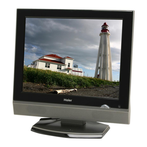
Haier TDVCF2016 User manual

0/54
F6B
COLOUR TELEVISION
SERVICEMANUAL
Features
51CMpureflatpicturetube
CCD function
181 programpresetting andmemory
Parental control
InnerDVD
InnerVCR
AVstereoandMTS
Models
TDVCF2016
TV-8888-69

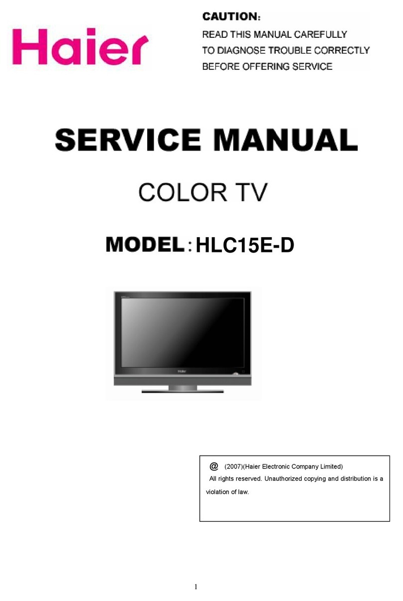
ColorTelevisionModel:20S62(TDVCF2016)
1/54
CONTENTS
1ProductCodeilluminationandSeries Introduction --------------------2
2Features --------------------------------------------------------------------------------3
3Specifications-------------------------------------------------------------------------4
4SafetyPrecautions-------------------------------------------------------------------5
5WarningandCautions--------------------------------------------------------------6
6Netdimension------------------------------------------------------------------------12
7Partsand Functions----------------------------------------------------------------13
8RemoteControllerFunctions----------------------------------------------------14
9Maintenance Service --------------------------------------------------------------16
10CircuitDiagram-----------------------------------------------------------------------22
11CircuitExplanation------------------------------------------------------------------23
12Adjustment-----------------------------------------------------------------------------28

ColorTelevisionModel:20S62(TDVCF2016)
2/54
1. ProductCodeilluminationandSeries Introduction
20 S62
CRTsize(unit:inch)
VCR/DVD/TVcombine
Modelseriesofaspectnumber

2.
Features
Color Television Model
:
20S62(TDVCF2016)
MODEL:20S62
MODEL:20
S62
N
O.
ITEM
FUNCTION
A
m
e
r
i
c
a
NO
.
ITEM
FUNCTION
A
m
e
r
i
ca
1
M
ain IC LA76834 24
Digital curtain
×
2
C
RT Pure flat 25
Slow fading on & off
×
3
C
olor system NTSC 26
Semitransparent menu
√
4
A
udio system M 27
N
o-flashing channel changing
×
5
NO
.of channels 181 28
ZOOM
×
6
OS
D language English/French/Sp
anish
29
16:9 mode
×
7
PICTURE
M
ulti-picture modes 1 30
Games
×
8
A
V stereo
√
31
Calendar
×
9
S
uper woofer
×
32
Child-lock
×
10
S
urrounding sound
×
33
Multi-functional lock
×
11
T
reble/bass boost
√
34
N
o-picture listening
×
12
L
eft/right balancer
√
35
Background light
×
13
N
ICAM
×
36
Auto-timer on
√
14
M
ulti-audio modes
×
37
CCD
√
15
T
one adjuster
×
38
SOFTWA
RE
V-CHIP
√
16
M
TS/SAP
√
39
NO
. of built-in speakers 2
17
AUDIO
A
u
t
o
-
v
o
l
u
m
e
l
e
v
e
li
n
g
×
40
A
ud
i
o
o
u
t
put p
o
w
e
r
(
W
)
2*1.5W
18
A
V
i
n
p
u
t
back 1,front 1 41
Total power input
(
W
)
100W
19
A
V
o
u
t
pu
t
√
42
Voltage range
(
V
)
120V
20
DV
D
t
e
r
m
i
n
a
l
×
43
Power frequency
(
Hz
)
60HZ
21
S
-
v
i
d
e
o
j
a
c
k
×
44
Ti
m
e
o
f
s
l
ee
p
tim
e
r
(
M
I
NS
)
120
22
H
eadphone socket front 45
N
et weight(KG) 25
23
JACK
SCART socket
×
46
Gross weight(KG) 27.5
*
Inner
D
VD
inner
D
V
D
fun
c
tion
√
47
N
et dimension(MM) 570*480*51
0
*
inner
V
CR
fun
c
tion
√
48
Packaged dimension(MM) 640*550*56
0
HiFi
√
49
Q
u
a
n
t
it
y
f
o
r
2
0
'
c
o
n
t
a
i
n
e
r
×
Inner
V
CR
SP/EP
√
50
Quantity for 40' container
×
51
PARA
ME
TER
Quantity for 40' high container
×
3/54

ColorTelevisionModel:20S62(TDVCF2016)
4/54
3. Specifications
lPOWERSUPPLY:AC120V, 60 Hz
lTuning system: FStuner
lIF:45.75MHz
lPowerconsumption: 100W
lAntenna inputimpedance: 75Ω
lReceivingsystem:
a)Colorsystem: NTSC
b)BroadcastTVsystem:M
lLanguagedisplayed: English/French/Spanish
lVideo input: 1.0VP-P (75Ω)
lAudioinput: 436mVrms(40KΩ)
lVCR system: NTSC, HiFi, SP/EP;
lDVDdistrict mode: 1;
Specifications

ColorTelevisionModel:20S62(TDVCF2016)
5/54
4.SafetyPrecautions
IMPORTANTSAFETYNOTICE
Manyelectricalidentifythesepartsandmechanicalpartsinthischassishavespecial
safety-related characteristics! Inthe SchematicDiagramand Replacement PartsList.
It isessentialthatthesespecialsafetypartsshouldbe replacedwiththesamecomponents
asrecommended inthismanualtoprevent X-RADIATION, Shock, Fire, orotherHazards.
Donot modifythe originaldesign without permission of themanufacturer.
General Guidance
AnIsolation Transformershouldalways be used during theservicing ofareceiverwhose
chassisisnotisolatedfromthe ACpowerline.Useatransformerofadequatepowerrating
asthisprotectsthe technician fromaccidentsthatmightresultinpersonalinjurycaused by
electricalshocks.
It willalsoprotectthe receiverand itscomponentsfrombeing damaged byaccidentalshorts
of the circuitrythat might be inadvertentlyintroduced during theserviceoperation.
If anyfuse(orFusibleResistor)inthisTVreceiverisblown, replaceit withaspecified one.
Whenreplacingahighwattage resistor(Oxide MetalFilmResistor,over1W),keep the
resistor10mm awayfromPCB.
Keep wiresawayfromhigh voltageorhigh temperatureparts.
Due tothe highvacuumand large surfacearea ofthe picturetube,extremecareshouldbe
taken inhandling the PictureTube. Donotlift the PictureTube byitsNeck.
X-RAYRadiation
Warning:
The sourceofX-RAYRADIATIONinthisTVreceiveristhe HighVoltage Sectionandthe
PictureTube.
Forcontinued X-RAYRADIATIONprotection,the replacementtube mustbe ofthe same
type asspecifiedintheReplacement PartsList.
Beforereturningthe receivertothecustomer,
Always performan ACleakage currentcheckon theexposedmetallicpartsofthe cabinet,
suchasantennas,terminals,etc.,tomakesurethatthesetissafetooperatewithoutany
dangerof electricalshock.
SafetyPrecautions

ColorTelevisionModel:20S62(TDVCF2016)
6/54
5. Warning andCautions
1.WhenyoucleantheTVset,pleasepull
outthepowerplugfromACoutlet. Don't
cleanthecabinetandthescreenwith
benzene,petrolandotherchemicals.
4.TopreventtheTVsetfromfiringand
electricshock,don't
maketheTVsetrain
ormoisture.
2.
Inordertoprolongtheusinglifeofthe
TVset, pleaseplaceitonaventilated
place.
5.Don'topenthebackcover,otherwiseitis
possibletodamagethe componentsinthe
TVsetandharmyou.
3.
Don'tplacethe
TVsetinthe
sunshineornear
heatsource.
6.WhentheTVsetisn'tgoing tobeused
forlongtimeoritisinthunderand
lightening,pleasepullouttheplugfromAC
outletandtheantennaplugfromthecover
oftheTVset.
Explanationonthe displaytube
Generally,it isnotneededtocleanthetubesurface.However, ifnecessary,itssurfacecanbe
cleanedwithadrycotton clothaftercuttingoffthepower.Don'tuseanycleanser.Ifusinghard
cloth,thetubesurfacewill be damaged.
CAUTION: Beforeservicingreceiverscoveredbythisservicemanualanditssupplements
and addenda,read and followthe SAFETYPRECAUTIONS.
NOTE: If unforeseen circumstancescreateconflictbetween the following servicing
precautionsandanyofthe safetyprecautions,always followthe safetyprecautions.

ColorTelevisionModel:20S62(TDVCF2016)
7/54
Remember:SafetyFirst.
General ServicingPrecautions
1.Always unplug the receiverACpowercordfromthe ACpowersourcebefore:
a.Removingorreinstallinganycomponent, circuitboardmoduleoranyotherassembly
of the receiver.
b.Disconnecting orreconnecting anyreceiverelectricalplugorotherelectrical
connection.
c.Connecting atest substituteinparallelwithanelectrolyticcapacitorinthe receiver.
CAUTION: Awrong substitutionpartorincorrectinstallation polarityofelectrolytic
capacitorsmayresultinan explosion hazard.
d.Discharging the picturetubeanode.
2.Testhighvoltage onlybymeasuringitwithan appropriatehighvoltage meterorother
voltage-measuringdevice(DVM,FETVOM,etc.)equippedwithasuitablehighvoltage
probe. Donot test high voltage by “drawinganarc”.
3.Discharge the picturetube anode onlyby(a)firstconnecting one end ofan insulated clip
leadtothe degaussingorkine aquadaggrounding systemshieldatthe pointwherethe
picturetube socketgroundlead isconnected,and then (b)touchthe otherendofthe
insulated clipleadtothepicturetube anodebutton,usinganinsulatinghandletoavoid
personalcontact withhigh voltage.
4.Donot spraychemicalson ornearthisreceiveroranyofitsassemblies.
5.Unless specified otherwiseinthisservicemanual,clean electricalcontactsonlyby
applying the following mixturetothe contactswithapipecleaner,cotton-tipped stick or
comparablenonabrasiveapplicator;10%(byvolume)Acetone and 90%(byvolume)
isopropylalcohol(90%-99%strength)
CAUTION: Thisisaflammablemixture.
Unless specified otherwiseinthisservicemanual,lubrication of contactsisnotrequired.
6.Donotdefeatanyplug/socketB+voltage interlocks withwhichreceiverscovered by
thisservicemanualmight beequipped.
7.DonotapplyACpowertothisinstrumentand/oranyofitselectricalassembliesunless
allsolid-statedeviceheatsinks arecorrectlyinstalled.
8.Always connectthe testreceivergroundlead tothereceiverchassisground before
connecting the testreceiverpositivelead.
Always removethe test receiverground leadlast.
9.Usewiththisreceiveronlythe test fixturesspecified inthisservicemanual.
CAUTION: Donot connect the test fixtureground straptoanyheat sinkinthisreceiver.
ElectrostaticallySensitive(ES)Devices
ColorTelevisionModel:20S62(TDVCF2016)
8/54
Somesemiconductor(solidstate)devicescanbe damaged easilybystaticelectricity.Such
componentsareusuallycalledElectrostaticallySensitive(ES)Devices.Examplesoftypical
ES devicesareintegratedcircuitsand somefieldeffecttransistorsand semiconductor “chip”
components.The followingtechniquesshouldbeused tohelpreducethe incidenceof
component damage caused bystaticelectricity.
1.Immediatelybeforehandling anysemiconductorcomponent orsemiconductor-equipped
assembly,drainoffanyelectrostaticchargeon yourbodybytouching aknownearth
ground.Alternatively,obtainandwearacommerciallyavailabledischargingwriststrap
device,whichshouldberemoved topreventpotentialshock priortoapplyingpowertothe
unitundertest.
2.Afterremoving an electricalassemblyequipped withES devices,placethe assemblyon
aconductivesurfacesuchasaluminumfoil,topreventelectrostaticchargebuildupor
exposureof theassembly.
3.Useonlyagrounded-tipsolderingiron tosolderorunsolderES devices.
4.Useonlyan anti-statictype folderremovaldevice.Somesolderremovaldevicesnot
classifiedas “anti-static”can generateelectricalchargessufficient todamage ES devices.
5.Donotusefreon-propelledchemicals.Thesecangenerateelectricalchargessufficient
todamage ES devices.
6.DonotremoveareplacementESdevicefromitsprotectivepackage until immediately
beforeyouarereadytoinstall it.(MostreplacementES devicesarepackaged withleads
electricallyshortedtogetherbyconductivefoam,aluminumfoilorcomparableconductive
material).
7.Immediatelybeforeremoving the protectivematerialfromthe leadsof areplacementES
device,touchthe protectivematerialtothe chassisorcircuitassemblyintowhichthe
devicewillbe installed.
CAUTION: Besurenopowerisappliedtothe chassisorcircuit,andobserveallother
safetyprecautions.
8.Minimizebodilymotionswhen handlingunpackaged replacementES devices.
(Otherwiseevensomenormallyharmless motionssuchasmutualbrushingofyour
clothes fabricorlifting ofyourfootfromacarpeted floormightgeneratestaticelectricity
sufficient todamage an ES device.)
General SolderingGuidelines
1.Useagrounded-tip,low-wattage solderingiron and appropriatetipsizeandshapethat
willmaintaintiptemperaturewithinthe rangeof 500oFto600oF.
2.Usean appropriategauge ofRMAresin-coresoldercomposed of60 partstin/40 parts
lead.
3.Keep the soldering iron tipclean andwelltinned.
4.Thoroughlyclean the surfacestobesoldered. Useamall wirebristle(0.5inch, or1.25cm)
brushwithametalhandle. Donot usefreon-propelled spay-on cleaners.

ColorTelevisionModel:20S62(TDVCF2016)
9/54
5.Usethe following unsoldering technique
a.Allowthe solderingiron tiptoreachnormaltemperature. (500o Fto600o F)
b.Heating the component lead untilthe soldermelts.
c.Quicklydrawthe melted solderwithan anti-static,suction-type solderremovaldevice
withsolderbraid.
CAUTION: Workquicklytoavoidoverheating the circuit boardprintedfoil.
6.Usethe following unsoldering technique
a.Allowthe solderingiron tiptoreachnormaltemperature. (500o Fto600o F)
b.First, holdthe soldering irontipand solderthestrand against the componentlead until
the soldermelts.
c.Quicklymovethe soldering iron tiptothejunction ofthe componentleadandthe
printed circuitfoil,and holditthereonlyuntil the solderflowsontoand around both
the component lead andthe foil.
CAUTION: Workquicklytoavoidoverheating the circuit boardprintedfoil.
d.Closelyinspectthesolderareaandremoveanyexcess orsplashedsolderwitha
small wire-bristlebrush.
Remove/Replacement
Somechassiscircuitboardshaveslotted holes(oblong)through whichthe ICleadsare
inserted and then bentflatagainstthecircuitfoil.When holesareofslotted type,the
followingtechnique shouldbe used toremoveand replacethe IC.When working withboards
usingthe familiarroundhole, usethe standardtechniqueasoutlined.
Removal
Desolderand straighteneachICleadinone operationbygentlyprying up onthelead with
the soldering irontipasthe soldermelts.
Drawawaythe melted solderwithananti-staticsuction-typesolderremovaldevice(orwith
solderbraid)beforeremoving the IC.
Replacement
Carefullyinsert the replacement ICinthe circuitboard.
Carefullybend eachIClead against thecircuitfoilpadand solderit.
Cleanthesolderedareaswithasmallwire-bristlebrush.(It isnotnecessarytoreapply
acryliccoating tothe areas).
Small-Signal”DiscreteTransistor
Removal/Replacement
Removethe defectivetransistorbyclipping itsleadsascloseaspossibletothe component
body.
Bend intoa “U”shape the end ofeachof threeleadsremainingon thecircuit board.

ColorTelevisionModel:20S62(TDVCF2016)
10/54
Bend intoa “U”shape the replacement transistorleads.
Connectthe replacementtransistorleadstothe corresponding leadsextendingfromthe
circuitboardand crimpthe “U”withlong noseplierstoinsuremetaltometalcontactthen
soldereachconnection.
PowerOutput,TransistorDevice
Removal/Replacement
Heat and removeallsolderfromaround the transistorleads.
Removethe heat sinkmounting screw(if soequipped).
Carefullyremovethe transistorfromthe heatsinkof the circuit board.
Insert newtransistorinthe circuitboard.
Soldereachtransistorlead, and clipoff excess lead.
Replaceheatsink.
DiodeRemoval/Replacement
Removedefectivediode byclippingitsleadsascloseaspossibletodiode body.
Bend the tworemaining leadsperpendicularlytothe circuit board.
Observing diode polarity,wrap eachlead ofthe newdiode roundthe corresponding leadon
the circuit board.
Securelycrimpeachconnectionand solderit.
Inspect(onthe circuitboardcopperside)the solderjointsofthe two “original”leads.If they
arenot shiny, reheat themand if necessary, applyadditionalsolder.
Fuse andConventional Resistor
Removal/Replacement
1.Clipeachfuseorresistorlead at top of the circuit boardhollowstake.
2.Securelycrimpthe leadsofreplacement component around notchat staketop.
3.Solderthe connections
CAUTION: Maintainoriginalspacingbetween the replaced componentand adjacent
componentsand the circuitboardtopreventexcessivecomponent temperatures.
CircuitBoardFoil Repair
Excessiveheatappliedtothe copperfoil ofanyprinted circuitboardwill weaken the
adhesivethatbondsfoiltothe circuitboardcausing the foiltoseparatefromor “lift-off”the
board.Thefollowingguidelinesandproceduresshouldbe followed wheneverthiscondition
isencountered.
AtICConnections
TorepairadefectivecopperpatternatICconnectionsusethefollowingproceduretoinstall a
jumperwireon the copperpatternside ofthecircuitboard.(Usethistechnique onlyonIC
connections).

ColorTelevisionModel:20S62(TDVCF2016)
11/54
1.Carefullyremovethe damaged copperpatternwithasharpknife. (Removeonlyasmuch
copperasabsolutelynecessary).
2.Carefullyscratchawaythe solderresistand acryliccoating(ifused)fromthe end ofthe
remainingcopperpattern.
3.Bend asmall “U”inoneend ofasmall gaugejumperwireand carefullycrimpitaround
the ICpin. Solderthe ICconnection.
4.Routethe jumperwirealong thepathoftheout-awaycopperpatternand letitoverlap
the previouslyscraped endofthe good copperpattern.Solderthe overlapped area and
clipoff anyexcess jumperwire.
Atotherconnections
Usethe following technique torepairthe defectivecopperpatternatconnectionsotherthan
ICPins.Thistechnique involvesthe installation ofajumperwireon the componentside of
the circuit board.
1.Removethe defectivecopperpatternwithasharpknife.
Removeatleast1/4inchofcopper,toinsurethatahazardouscondition willnotexistif
the jumperwireopens.
2.Tracealongthe copperpatternfrombothsidesofthe patternbreakand locatethe
nearest component thatisdirectlyconnected tothe affected copperpattern.
3.Connectinsulated 20-gaugejumperwirefromthe lead ofthe nearestcomponenton one
side of the patternbreaktothelead of the nearest component on theotherside.
Carefullycrimpand solderthe connections.
CAUTION: Besurethe insulated jumperwireisdressed sothatitdoesnottouch
componentsorsharpedges.

ColorTelevisionModel:20S62(TDVCF2016)
12/54
5.Net dimension
TheNetdimension(MM)is570*480*510.

ColorTelevisionModel:20S62(TDVCF2016)
13/54
7. PartsandFunctions
(1).Frontpanel oftheTVset
(2). Rearpanel oftheTVset

ColorTelevisionModel:20S62(TDVCF2016)
14/54
8. RemoteControllerFunctions

Color Television Model
:
20S62(TDVCF2016)
9.
Maintenance
Service
and
Trouble
shooting
A.
Principle
integrated
circuits
A1.20S62 color TV set composed of the following sections
position
specification
model
supplier
I801
power
IC
STR-W67
35
SanKen
T804
power
switching
transformer
BCK-08A
6
F-3
Ningbo
Lishunda
T401
FBT
JF0501-
1
9810B
Wuxi
Jingshi
I808/I806
5V
IC
KIA278R
05
/
I807
12V
IC
KIA78S1
2
P
KEC
I805
9V
IC
KIA78R09
/
I804
5V
IC
L7805CV
/
Q401
audion
f
or
H
d
eflec
t
ion
2SD2499
Toshiba
I301
Vertica
l
defl
e
ction
IC
LA78040
Sanyo
I803
2.5V
IC
KA431AZT
A
/
I802
phototransistor
PC817B
Sharp
I501
CVBS
de
c
oding
and
T
V
IC
LA76834
N
M
Sanyo
I201
VCR
dec
o
ding
I
C
LA71207M
Sanyo
IH01
HiFi
and
MTS
I
C
LA72670
B
M
Sanyo
I701
CPU
IC
M37762X
XX
CASTI
IS01
switchi
ng
MM1492
MITSUMI
I601
sound
p
r
ocess
IC
TDA7449
ST
I502
comb
fi
l
ter
IC
TDA9183P
Philips
I602
sound
a
m
plifi
e
r
LA4635A
Sanyo
I703
memory
I
C
AT24C08
Microch
i
p
I702
audion
KIA7033P
DVD-768
34
sof
t
ware
DS-C011
B
-A
DESAY
VCR
NTSC-DE
C
K
DAEWOO
15/54

ColorTelevisionModel:20S62(TDVCF2016)
16/54

ColorTelevisionModel:20S62(TDVCF2016)
17/54

ColorTelevisionModel:20S62(TDVCF2016)
18/54

Other manuals for TDVCF2016
1
Table of contents
Other Haier TV manuals

Haier
Haier HL15T Building instructions

Haier
Haier LC-3710D User manual

Haier
Haier HE24D4MFA User manual

Haier
Haier 39G2000 User manual

Haier
Haier L22C1120 Assembly instructions

Haier
Haier L24F6 User manual

Haier
Haier 29F9D User manual

Haier
Haier 25F3A User manual

Haier
Haier L42V6-A8K User manual

Haier
Haier L37TA6A User manual

Haier
Haier LE55B1381 User manual

Haier
Haier HTAF29S User manual

Haier
Haier HT-2599 User manual

Haier
Haier 21F9K-T Instruction and safety manual

Haier
Haier L32A8A Operating instructions

Haier
Haier DX-RCRT20-09 User manual

Haier
Haier L29V6-A1 User manual

Haier
Haier HT-2588 User manual

Haier
Haier LE24F7000 User manual

Haier
Haier LE24F6550 User manual