Hakki Pilke 38 Pro PTO User manual

1 / 40
Hakki Pilke 38 Pro Translation Version 3
Hakki Pilke
38 Pro
FIREWOOD PROCESSOR
–Instructions for assembly, operation and maintenance
–EC Declaration of Conformity
–Safety instructions
–Guarantee terms
MAASELÄN KONE OY
Valimotie 1, FI-85800 Haapajärvi, Finland
Tel. +358 (0)8 772 7300
info@hakkipilke.fi
www.hakkipilke.fi
ENGLISH
The operator must read and understand these
instructions before operating the machine!

2 / 40
Hakki Pilke 38 Pro Translation Version 3
Table of contents
1. General information.....................................................................................................................4
1.1. Introduction..............................................................................................................................................4
1.2. Purpose of use..........................................................................................................................................4
1.3. Machine models and basic information...................................................................................................4
1.4. Operating conditions................................................................................................................................4
1.5. Safety instructions....................................................................................................................................5
1.6. Noise and vibration ..................................................................................................................................5
1.7. Warning symbols ......................................................................................................................................5
2. Receipt and assembly...................................................................................................................7
2.1. Delivery inspection ...................................................................................................................................7
2.2. Lifting and moving the machine...............................................................................................................7
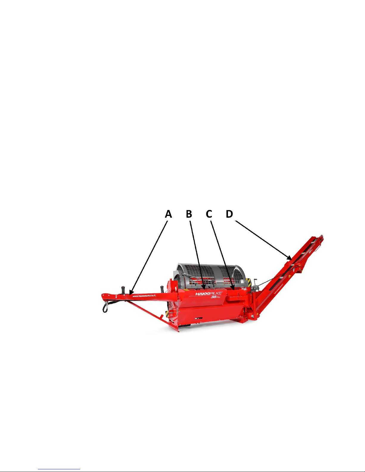
2.3. Main components of the machine ...........................................................................................................8
2.4. Preparing the machine for operation......................................... Virhe. Kirjanmerkkiä ei ole määritetty.
3. Control functions and setting up the machine ............................................................................9
3.1. Arranging the machine for operation and transport ...............................................................................9
3.1.1. Placing the in-feed conveyor in the operating or transport position ...............................................9
3.1.2. Placing the out-feed conveyor in the operating or transport position ..........................................10
3.2. Controls ..................................................................................................................................................11
3.2.1. Tractor drive....................................................................................................................................12
3.2.2. Electrical drive.................................................................................................................................13
3.2.3. Adjusting the log length ..................................................................................................................15
3.2.4. Using the out-feed conveyor ..........................................................................................................15
3.2.5. Splitting blade adjustment..............................................................................................................17
3.2.6. Using a sawdust removal device.....................................................................................................17
4. Operating the machine ..............................................................................................................17
4.1. Performing a test run on the machine ...................................................................................................17
4.2. Placing logs on the in-feed conveyor .....................................................................................................18
4.3. Feeding and sawing wood ......................................................................................................................18
4.3.1. Jamming of the cutting blade .........................................................................................................19
4.3.2. Sawing the last log ..........................................................................................................................19
4.3.3. Using the quick couplings of the additional hydraulics ..................................................................19
4.3.4. Using the quick couplings of the auxiliary feed rollers ...................................................................19
4.4. Log splitting ............................................................................................................................................20
4.4.1. Jamming of wood on the splitting blade.........................................................................................20

3 / 40
Hakki Pilke 38 Pro Translation Version 3
4.4.2. Resplitting or splitting without cutting ...........................................................................................20
4.4.3. Replacing the splitting blade...........................................................................................................21
4.4.4. Adjusting the stroke length of the splitting motion........................................................................22
4.5. Using the out-feed conveyor..................................................................................................................23
4.6. After use .................................................................................................................................................24
5. Machine maintenance ...............................................................................................................24
5.1. Cutting blade and drive end ...................................................................................................................24
5.1.1. Replacing and tensioning the saw chain.........................................................................................25
5.1.2. Replacing the saw bar .....................................................................................................................26
5.2. Changing the multiplier gear’s oil ..........................................................................................................27
5.3. Changing the oil......................................................................................................................................27
5.4. Conveyor maintenance ..........................................................................................................................29
5.4.1. Replacing and tensioning the in-feed conveyor belt ......................................................................29
5.4.2. Replacing and tensioning the out-feed conveyor belt....................................................................30
5.4.3. Replacing the out-feed conveyor plates .........................................................................................30
5.5. Lubrication..............................................................................................................................................31
5.6. Saw chain lubrication .............................................................................................................................33
5.7. Solenoid and pressure regulating valves................................................................................................33
5.8. Washing and cleaning.............................................................................................................................33
6. Storage .......................................................................................................................................33
7. Maintenance table .....................................................................................................................33
8. Failures and remedial measures ................................................................................................35
9. Electrical diagrams .....................................................................................................................36
10. Guarantee terms ........................................................................................................................37
EC Declaration of Conformity for the machine..................................................................................38

4 / 40
Hakki Pilke 38 Pro Translation Version 3
1. General information
1.1. Introduction
The purpose of this manual is to ensure that the machine is used in the manner intended by the
manufacturer, taking safety into consideration. Everyone operating the machine or working in close proximity
to it must study this manual carefully.
Operators of the machine are expected to have basic skills in tractor handling, such as utilising the cardan
shaft drive and the tractor's lifting equipment. Before commencing work, operators must also familiarise
themselves with the machine's control and safety equipment, and ensure their proper operation.
Additional information on Maaselän Kone Oy's products is available on our website at www.hakkipilke.fi.
Keep this manual in the immediate vicinity of the machine.
1.2. Purpose of use
The Hakki Pilke 38 Pro firewood processor is designed for preparing firewood from pruned wood or logs. The
firewood processor must not be used to process any treated wood, such as is found in construction waste.
Sand, nails or other impurities in the wood may damage the machine.
The maximum diameter of the logs to be processed is 38 cm. This limit must not be exceeded. When
estimating the diameter of the log you are about to cut, note that the shape of the log and other factors, such
as branches and burrs, make the actual diameter larger, and may prevent the log from being fed into the
machine. The splitting channel is designed for logs up to 60 cm in length, which should never be exceeded.
1.3. Machine models and basic information
Model
PTO
Combi
Driving power
Tractor's cardan shaft (PTO)
PTO
Electrical
Weight
990 kg
1060 kg
TR/Electrical drive
min. 25 hp/max 500 r/min 10 kW (min 25 A fuse)
Height/width/length
in the transport position 2,500/2,460/1,300 (mm)
Infeed/outfeed conveyor
2,200/4,000 (mm)
Saw bar/chain
bar: 16” groove 1.5 mm, chain: 68 loops, pitch 0.325”
Max log diameter
38 cm
Max/min length
Firewood max 60 cm; min 22 cm
The machine’s serial number, date of manufacture, weight, operating voltage (electrically operated machines)
and model are indicated on the grey type plate located on the machine frame below the locking latch of the
output conveyor, on the right side of the operator.
1.4. Operating conditions
The temperature range within which the machine can be operated is -20 to +30 °C. In the winter, the
operator must ensure that there is no risk of slipping in the working area.
The working area must be level and clear of unnecessary items. No unauthorised persons are allowed
to enter the working area. The machine may only be used in sufficient lighting conditions.
The machine may not be used indoors.

5 / 40
Hakki Pilke 38 Pro Translation Version 3
1.5. Safety instructions
This device is intended to be operated by only one operator. The danger zone is 10 m from the
machine.
Persons under 18 years of age may not operate the machine.
The operator must ensure that the use of the device does not cause danger to others and that there
are no unauthorised persons in the danger zone.
The machine must not be operated while under the influence of alcohol or other drugs, or when tired.
The machine must not be operated unless the operator has familiarised themselves with this
instruction manual.
The machine has been designed solely for making firewood.
The machine must be placed in the transport position whenever it is moved. When transporting the
machine on a public road, it must be equipped with additional lights.
The operator is not permitted to modify the structure or operation of the machine or remove
protective equipment.
The operator must wear ear protectors, sufficiently tight-fitting work clothing and gloves, protective
goggles and safety footwear.
The operator must ensure sufficient ventilation around the machine. If necessary, respiratory
protection must be worn.
Before starting up the machine, the operator must ensure that the machine and its guards are intact.
When powering the machine with a tractor, the operator must ensure that the cardan shaft is
undamaged and that the selected rpm range is correct. The machine must be attached to the tractor's
lifting equipment during operation.
Before starting up the firewood processor, the operator must ensure that all the control and safety
devices are functional.
When cleaning the machine or carrying out any maintenance, it must be disconnected from its power
source.
1.6. Noise and vibration
The A-weighted sound pressure level at the working location is 87.0 dB (A), and the sound power level
is 98.0 dB (A). The vibration values do not exceed 2.5 m/s2.
1.7. Warning symbols
Read the machine’s manual before
operating the machine.
Wear eye and ear protection.
Wear safety footwear and
work gloves.

6 / 40
Hakki Pilke 38 Pro Translation Version 3
Do not wear any loose items of
clothing.
Always grab the piece of
wood or log from the side.
Lifting point for a forklift.
Beware of moving parts.
Beware of the cardan shaft.
Beware of the saw chain.
Beware of the splitting blade.
Only one person may
operate the machine.
Disconnect the power supply
before any maintenance
procedures.
The danger zone around the machine is
10 metres.
Risk of crushing

7 / 40
Hakki Pilke 38 Pro Translation Version 3
The maximum permitted angle of the
conveyor is 40°.
Do not walk under the conveyor.
The maximum speed for the
cardan shaft is 500 rpm.
The rotation direction is in the
direction of the arrow.
Hydraulic oil
Saw chain oil
Danger zone
Lubrication point
2. Receipt and assembly
2.1. Delivery inspection
Dispose of the machine’s packaging materials in an environmentally friendly manner.
Check that the machine has not sustained any damage during transport, and ensure that all necessary parts
are included in the package. In the event of any defects or damage, contact the retailer immediately.
2.2. Lifting and moving the machine
When moving the machine, make
sure that the moving and lifting
capacity of your tractor or forklift is
sufficient for the weight of the
machine. Only lift the machine by the
indicated lifting points or with the
lifting equipment of the tractor.
Figure 1. Lifting points of the machine

8 / 40
Hakki Pilke 38 Pro Translation Version 3
When connecting the machine to the tractor's lifting equipment, the tractor cabin must be free of people, in
order to prevent any accidental contact with the controls. Check all the connecting devices of the tractor and
the firewood processor before connecting them. Never use faulty equipment. The pins that are used to
connect the pushbars and drawbars to the machine must be of the correct size, and the appropriate locking
pins must be used to secure them.
The machine must be placed in the transport position if it is to be moved more than 5 metres. Exercise
extreme caution when moving the machine in the operating position. Always lower the machine to the
ground when you stop.
Note! Incorrect lifting may cause a hazardous situation or damage the machine.
2.3. Main components of the machine
The Hakki Pilke 38 Pro is a firewood processor with fully hydraulic controls. In other words, all of the
machine's functions are controlled hydraulically with operating levers on the machine's control panel. The
guard of the cutting and splitting section is interlocked with the machine's operation: opening the guard stops
all functions.
A. In-feed
conveyor
B. Control unit
C. Cutting and
splitting unit
D. Out-feed
conveyor
Figure 2. Main components of the machine

9 / 40
Hakki Pilke 38 Pro Translation Version 3
3. Control functions and setting up the machine
3.1. Arranging the machine for operation and transport
Before arranging the machine for operation and using it, ensure that the operating conditions, detailed in
Section 1.4, are met and review the safety instructions in Section 1.5.
Note! Inspect and clean the machine before rearranging the machine.
3.1.1. Placing the in-feed conveyor in the operating or transport position
Place the in-feed conveyor in the operating
position as follows:
1. Ensure that sufficient room is
available to lower the input
conveyor (approx. 2 m).
2. Release the lock by lifting handle
A upward with your left hand.
Note! At the same time, hold the
end of the input conveyor with
your right hand!
3. Lower the input conveyor down
with your right hand and, at the
same time, use your left hand to
guide support leg C into slots B, as
instructed in Figure 4.
When placing the input conveyor in the
transport position, lift the conveyor to the
upper position and ensure that locking
latch A locks the conveyor, i.e. that lock A
is inserted in the slot circled in Figure 3.
Figure 3.
Figure 4.

10 / 40
Hakki Pilke 38 Pro Translation Version 3
3.1.2. Placing the out-feed conveyor in the operating or transport position
Place the out-feed conveyor in the operating position as follows:
1. Ensure that there is
sufficient room for
opening the out-feed
conveyor.
2. Turn off the machine.
3. Keep lock A open and
lower the out-feed
conveyor down with a
winch to its lowest
position.
Note! Leave sufficient
clearance (approx.
30 cm) for the
discharge opening of
the conveyor.
4. Turn the upper section of
the conveyor to the
operating position with
handle C at the upper
end.
5. Turn the out-feed
conveyor's support bar B
to the side.
6. Straighten splitting
groove guard E into the
operating position.
7. Use a winch to lift the
conveyor to the desired
angle (max 40°), and use
lock D on the bottom of
the conveyor to lock the
upper section of the
output conveyor in the
operating position.
Figure 5.
Figure 6. Figure 7.
Figure 8. Figure 9.

11 / 40
Hakki Pilke 38 Pro Translation Version 3
Place the out-feed conveyor in the transport position as follows:
1. Turn off the machine.
2. Release lock D, which holds the upper section of the conveyor in place, and lower the conveyor to the
lowest possible position with the winch.
3. Position support bar B over the belt, and fold the upper section of the conveyor onto the lower section
with handle C.
4. Turn the conveyor to the middle position. See Section 3.2.4.
5. Turn splitting groove guard E into transport position, as shown in Figure 9.
6. Lift the conveyor with the winch until it locks into the raised position. Ensure that lock A connects
firmly.
Note! Do not stand on the out-feed conveyor! Do not use the winch if the rope
is worn!
3.2. Controls
Figure 10. Controls
Operation of the controls in Figure 10
A. Out-feed conveyor belt control valve.
- Front position causes the belt to move forward.
- Middle position causes the belt to stop.
- Back position causes the belt to move backward.

12 / 40
Hakki Pilke 38 Pro Translation Version 3
B. Adjustment for the running speed of the out-feed
conveyor.
-Turning the knob anti-clockwise increases the
speed, and vice versa.
C. Wood gripper handle. With the handle, wood can
be pressed against the table during sawing in
order to make cutting the wood as safe and stable
as possible.
D. Accessory and out-feed conveyer swivel (optional)
control valve.
-Lever forwards/backwards: Out-feed conveyor
turns
left/right (optional)
-Lever right/left: Accessory control
E. Joystick for the sawing and splitting functions,
splitting blade and in-feed conveyor.
Operation of the controls in Figure 11
-Right/left: In-feed conveyor control
-Button A: Activation for splitting.
-Button B: HakkiCut™ control button for the
cutting function.
-Forwards/backwards: Splitting blade is
lowered/raised
Figure 11. Joystick
3.2.1. Tractor drive
A tractor-powered firewood processor is
connected to the tractor’s three-point
lifting devices and cardan shaft. To
connect the combi machine to the
cardan shaft, you have to move
protective cover A of the socket and
multiplier gear into a position where it
covers the socket.
Connecting the cardan shaft is a task for
only one person. When connecting the
machine to the tractor, there must be no
one in the tractor cabin, so as to prevent
any accidental contact with the controls.
Check all the connecting devices of the
tractor and the firewood processor
before connecting them. Never use

13 / 40
Hakki Pilke 38 Pro Translation Version 3
faulty equipment.
Connect the power cable for the electric
controls (in Figure 14) to the 12 V, 3-pin
socket for a work machine.
Figure 12.
When using the cardan shaft, observe any instructions provided by the manufacturer of the shaft. The
machine requires 25 hp of power, which must be taken into account with regard to the capacity of the cardan
shaft. A suitable cardan shaft is of power class four. Check that the shaft is properly locked to the splined shaft
of the angle transmission. Connect the chain that prevents the turning motion of the guard to hole B. Hang
the cardan shaft from hook C when the machine is not being operated and when it is disconnected from the
tractor. Finally, ensure that all connections are safe and secure. Never use a damaged or unprotected cardan
shaft.
Note! Tractor-powered machines must be attached to the lifting equipment of the tractor.
Note! The starter (Figure 15) only functions when the machine is powered by electricity.
3.2.2. Electrical drive
An electric-powered machine
is powered by a 10 kW
electric motor. The IP value
of the electric motor is 55.
The fuse must be at least
25 A. The electrical cable
must be at least 5 x 4 mm²,
recommended maximum
length is 30 m. In order to
connect the cable at the
combi machine, move
protective cover B of socket
A and the angle gear and
secure it into a position
where it covers the multiplier
gear, as in Figure 13.
In an electrically-powered
machine, the power cable of
the electric control is
connected to the socket on
the side of the machine.
Figure 13. The machine’s electrical drive

14 / 40
Hakki Pilke 38 Pro Translation Version 3
The machine is activated
using the green button of the
remote starter on the control
panel on the front panel of
the machine. If the electric
motor rotates in the wrong
direction (i.e. the machine
makes an abnormal noise
and the hydraulic functions
are inoperable), the current
phase is incorrect. We
recommend using an
extension cord that allows
you to switch the current
phase using a phase switch or
an adapter.
Note! If the extension cord
does not have a phase
switch, the electrical work
related to changing the
phase must only be
performed by an electrician.
Figure 14. Electrical connector of the electric control device
Figure 15. Starter

15 / 40
Hakki Pilke 38 Pro Translation Version 3
3.2.3. Adjusting the log length
The Hakki Pilke 38 Pro is equipped with a mechanical log measurement device with an incremented
adjustment value of 22–60 cm.
1. Turn the machine off and open the
machine’s guard.
2. When the wood limiter is in the
splitting position, set it to the
desired length by removing cotter
pin B in the limiter's locking pin
and by pulling out locking pin A.
Lock limiter plate C in the desired
position. Re-insert locking pin A
and cotter pin B.
Note! Turn the limiter plate to the
correct position according to the
thickness of the log. (See Figures 17
and 18). The wrong position may
cause damage to the machine!
Figure 17. Limiter plate position for large
logs of more than 25 cm in diameter
Figure 16. Log length adjustment
Figure 18. The limiter plate position for small logs
3.2.4. Using the out-feed conveyor
The Hakki Pilke 38 Pro firewood processor’s out-feed conveyor belt is driven by a hydraulic motor. To change
the speed of the belt, use adjuster B (Figure 10). The following describes how the conveyor can be turned
laterally by using turning lever A and handle B:

16 / 40
Hakki Pilke 38 Pro Translation Version 3
Figure 19.
Release the lock of the conveyor by pushing lever A towards the conveyor, and turn the conveyor to the
desired position with handle B.
If hydraulic turning of the conveyor (optional) is available, you can use control lever D (Figure 10) to swivel the
conveyer laterally. In other words, turning the lever forwards swivels the conveyer to the left, and turning
the lever backwards swivels the conveyer to the right.
The maximum operating angle for the out-feed conveyor is 40°. The maximum angle is indicated on the label
below and in the instructions attached to the out-feed conveyor.

17 / 40
Hakki Pilke 38 Pro Translation Version 3
3.2.5. Splitting blade adjustment
The machine’s splitting blade is controlled hydraulically with joystick E (Figure 10) (forwards => blade is
lowered, backwards => blade is raised). Logs should always be as centred as possible when passing the blade
in order to keep the size of the firewood consistent.
The blade can be lowered to the lowest position in one go by raising the blade to the upper position and
clearing the space under the blade. The machine must be shut down and disconnected from its power source
for the duration of the cleaning.
3.2.6. Using a sawdust removal device
A hydraulic dust collector is available as an accessory for the splitter. It allows you to collect sawdust for other
purposes. The sawdust removal device is on when the control valve is open, as in Figure 19b.
Figure 19b
4. Operating the machine
4.1. Performing a test run on the machine
The machine may not be used before a test run has been performed and all the functions of the machine have
been tested. Both the test run and testing can only be performed by a person who has studied the machine’s
manual.
Before the test run, all of the components of the firewood processor must be checked. If any faults or wear
and tear that may affect the safe use of the machine are discovered, the processor must not be used until the
faulty or worn component is replaced and safe use can be ensured.
1. Check that the guard for the firewood processor's cutting and splitting section is down.
2. Check that the in-feed and out-feed conveyors are in the operating position.
3. Ensure that the splitting groove is empty.
4. Make sure that you are familiar with the functions of the machine's controls. If necessary, see Section
3.2.
5. Activation.
6. Tractor drive: Insert the connector for the electric control device into the tractor's electrical socket.
Start the tractor and connect the power take-off, starting with a slow speed and increasing the speed to
a maximum of 500 rpm.

18 / 40
Hakki Pilke 38 Pro Translation Version 3
7. Electrical drive: Connect the cable to the socket of the firewood processor, start the machine by
pressing the start button and wait until the electric motor operates at full speed.
8. Start the splitting motion by pressing joystick button A (Figure 11). The splitting motion must be
normal.
9. Do the following to ensure that the saw chain lubrication functions automatically: (If necessary, see
Section 7.0.)
a. Perform a few sawing cycles without wood by pressing joystick button B (Figure 11).
b. Turn off the machine and disconnect it from the power source.
c. Open the guard and see if the saw chain has been supplied with oil.
10. Start the splitting cycle and stop it by opening the cradle guard of the cutting and splitting section.
11. Conduct a test run for the in-feed conveyor's feed and reverse motion with joystick E (Figure 10).
12. Activate the out-feed conveyor using lever A (Figure 10) and adjust the conveyor speed to an
appropriate level using control B (Figure 10). Also ensure that lever A stops and reverses the conveyor.
If a fault occurs during the test run, determine the cause of the fault and take remedial action as deemed
necessary. The machine must be shut down and disconnected from the power source for the duration of both
the diagnostics and repairs.
4.2. Placing logs on the in-feed conveyor
We recommend the use of auxiliary devices, such as the HakkiFeed 422 timber deck. If a timber deck is not
attached to the machine, the maximum allowed log length is 4.5 m. Always lift and place wood on the in-feed
conveyor in a safe manner that does not put the operator in danger.
Note! Placing logs directly on the in-feed conveyor with a loader is strictly prohibited.
Note! Ensure that the log's centre of gravity stays on the conveyor.
4.3. Feeding and sawing wood
The in-feed conveyor feeds the wood into the firewood processor. Turn joystick E (Figure 10) to the right to
feed wood into the machine. The feed can be reversed by turning the joystick to the left.
When feeding wood into the machine, make sure that it does not present a risk of your clothes, hands or
other parts getting caught in the machine, due to the shape of the log, for example. Do not use your hand to
guide the log into the cutting section. Adjust the wood measuring device to the desired length and make sure
that the speed of the out-feed conveyor belt is suitable by adjusting it.
1. Choose the log to process. Note that the maximum log diameter is 38 cm. The knottiness and shape of
the log can increase the diameter.
2. Use joystick E to feed the log into the machine with the in-feed conveyor. Turn the lever to the right
to activate the feed.
3. When the log stops at the mechanic measuring device for cutting, hold the log in place by placing
more pressure on wood gripper lever C (Figure 10).
4. Cut the log by pressing joystick push button B (Figure 11). This activates the HakkiCut™ function: the
saw chain starts rotating, the saw chain oil pump performs a pumping cycle and the saw bar moves
down at optimal power.
5. Return the saw bar to the upper position by releasing button B (Figure 11). This also stops the saw
chain.

19 / 40
Hakki Pilke 38 Pro Translation Version 3
4.3.1. Jamming of the cutting blade
If the cutting blade gets jammed in the log, stop sawing and try again on another section of the log. If the cut
is misaligned because the bar drags to one side, the degree of sharpness of the saw chain must be checked. A
chain that is not evenly sharp will always drag towards the blunter side, which will make cutting a thick log
impossible. Also check that the bar is not worn or crooked. On the other hand, sawing with an evenly dull
chain is inefficient, and the sawing chain must be sharpened or replaced (see Sections 5.1.1 and 5.1.2).
4.3.2. Sawing the last log
When sawing wood, the second to last piece should be sawn in such a way that the remaining piece is of a
sufficient length. This ensures that the log will stay firmly under the wood gripper and that the sawing will be
steady and safe. Drive the last log directly into the splitting section, and start the splitting process using
joystick button A (Figure 11).
4.3.3. Using the quick couplings of the additional hydraulics
Connect the additional hydraulics (e.g. when using the HakkiFeed 381 log lifter) by pushing the auxiliary
device’s hydraulic hoses into quick couplings A and B in Figure 20 (in Section 4.3.4). The hose with red marking
goes to higher quick coupling (also marked with red colour).
4.3.4. Using the quick couplings of the auxiliary feed rollers
The auxiliary feed rollers can be connected in series with the in-feed conveyor. This way, the rollers are
automatically synchronised to operate with the input conveyor when feeding logs using joystick E (Figure 10).
1. Connect the auxiliary feed roller
hoses to quick couplings C and D,
hose with red marking to higher
quick coupling
2. Remove the guard as instructed in
the instructions of point 2 of
Section 4.4.4.
3. Open cock E (Figure 21) to allow oil
to flow to the quick couplings
(Figure 20) C and D.
4. Make sure that the rotation
direction of the rollers is the same
as the conveyor’s direction. If
necessary, change the connections.
Figure 20.
C
D
B
A

20 / 40
Hakki Pilke 38 Pro Translation Version 3
Note! Cock E must always be
turned off (as in Figure 21)
whenever quick couplings C and D
(Figure 20) are not in use!
Figure 21.
4.4. Log splitting
The splitting slide of the machine performs a splitting cycle every time button A on the control lever E (Figure
11) is pressed. The splitting function is not available when the machine’s cover is open. The splitting cycle can
be stopped and reversed by opening and closing the machine’s cover.
4.4.1. Jamming of wood on the splitting blade
If a piece of wood gets jammed on the splitting blade in a situation where the splitting force is insufficient to
push the piece past the blade despite several attempts to do so, do the following:
1. Return the splitting beam to the initial position by opening and closing the machine’s protective
cover.
2. Lift the splitting blade to the highest possible position with lever E (in Figure 10) and activate the
splitting.
3. If necessary, cut a sufficiently thick piece of wood (approx. 20–25 cm) into the splitting channel and
activate the splitting cycle. The new piece will then push the jammed piece past the blade.
4. Lower the blade by approx. 10 cm and repeat step 3. Repeat step 4 until the jammed log has passed
the blade, piece by piece.
4.4.2. Resplitting or splitting without cutting
1. Raise the protective cover of the cutting and splitting channel.
2. Place the log you want to split in the splitting channel.
3. Close the protective cover of the cutting and splitting channel.
4. Activate the splitting cycle with button A (Figure 11).
The above procedure can be used to split wood without cutting it, as necessary.
E
This manual suits for next models
1
Table of contents
Other Hakki Pilke Log Splitter manuals
Popular Log Splitter manuals by other brands

Kity
Kity PV 6000 Translation from the original instruction manual

Posch
Posch SplitMaster 30 operating instructions

MTD
MTD Series 580 Operator's manual

Central Machinery
Central Machinery 61373 owner's manual

Brave
Brave EZ Split Owner/operator and safety manual

Garland
Garland CHOPPER 406 VE instruction manual