2 / 48
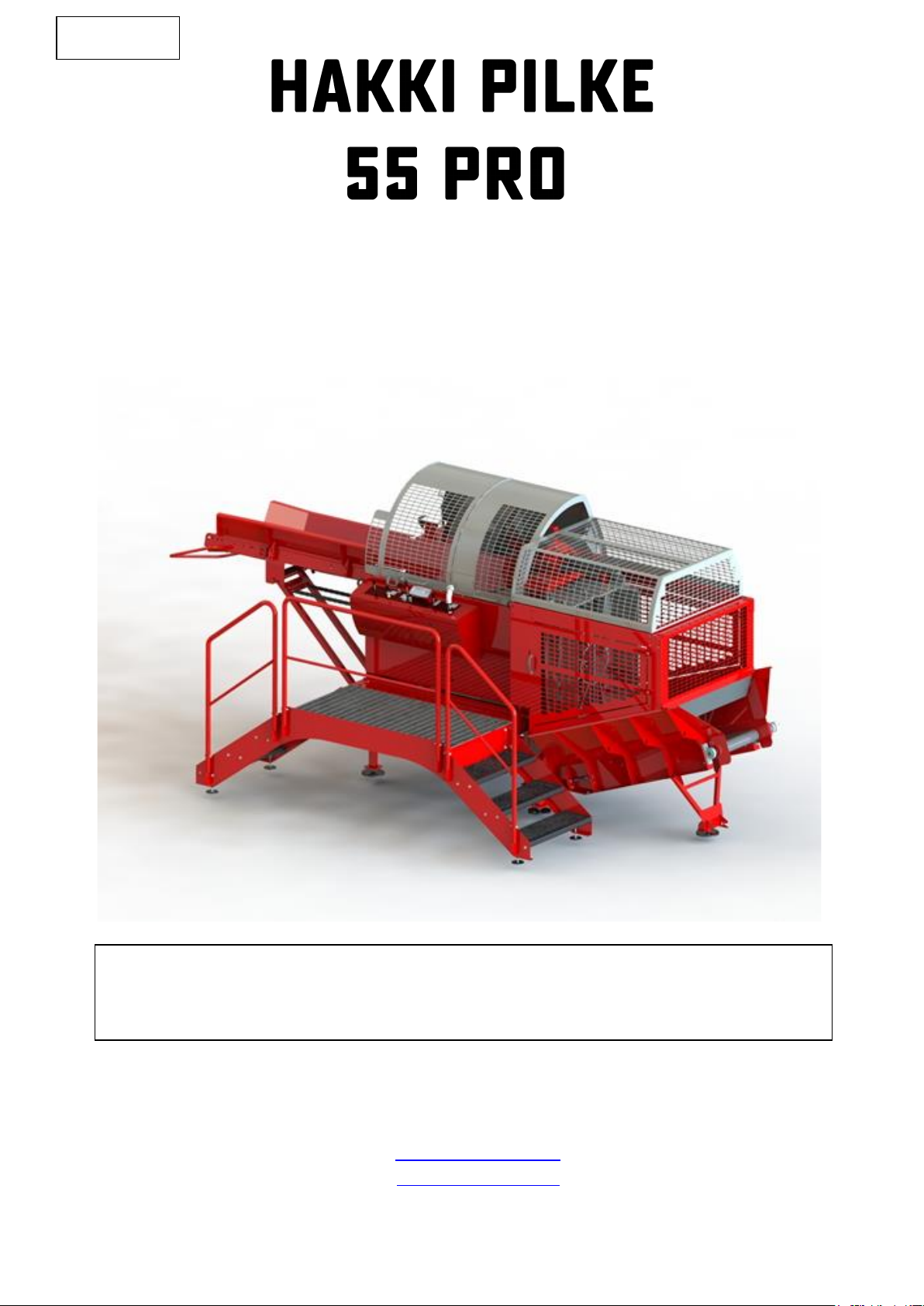
Hakki Pilke 55 Pro Translation Version 3-2022
Table of contents
1. General information.................................................................................................................... 4
1.1. Introduction...................................................................................................................................... 4
1.2. Purpose of use .................................................................................................................................. 4
1.3. Machine models and basic information........................................................................................... 4
1.4. Operating conditions ........................................................................................................................ 4
1.5. Safety instructions ............................................................................................................................ 5
1.6. Noise and vibration........................................................................................................................... 5
1.7. Warning symbols .............................................................................................................................. 5
2. Receipt and assembly.................................................................................................................. 7
2.1. Delivery inspection ........................................................................................................................... 7
2.2. Lifting and moving the machine ....................................................................................................... 7
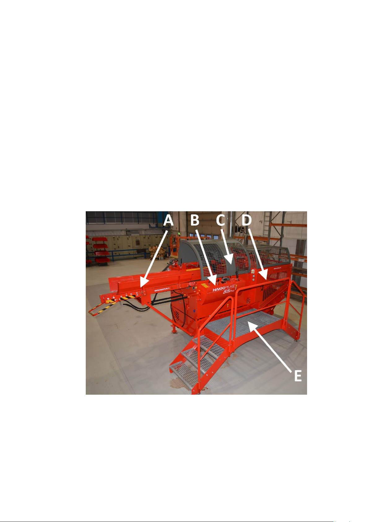
2.3. Main components of the machine ................................................................................................... 8
3. Control functions and setting up the machine............................................................................ 9
3.1. Preparing the machine for operation and transport........................................................................ 9
3.1.1. Placing the in-feed conveyor in the operating or storage position .......................................... 9
3.2. Controls........................................................................................................................................... 11
3.2.1. Using the machine’s monitor .................................................................................................. 13
3.2.2. Tractor drive ............................................................................................................................ 14
3.2.3. Electrical drive ......................................................................................................................... 15
3.2.4. Adjusting the log length .......................................................................................................... 16
3.2.5. Using the XL Conveyor out-feed conveyor (accessory)........................................................... 17
3.2.6. Adjusting and using the splitting knife.................................................................................... 18
3.2.7. Using the sawdust blower (accessory).................................................................................... 20
4. Operating the machine.............................................................................................................. 21
4.1. Performing a test run on the machine ........................................................................................... 21
4.2. Placing logs on the in-feed conveyor.............................................................................................. 22
4.3. Feeding and sawing wood .............................................................................................................. 22
4.3.1. Hydraulic log press .................................................................................................................. 22
4.3.2. Jamming of the cutting blade.................................................................................................. 23
4.3.3. Guide plates for falling wood pieces....................................................................................... 23
4.3.4. Sawing the last log................................................................................................................... 24
4.3.5. Using the quick couplings of the additional hydraulics........................................................... 24
4.3.6. Connecting a log table’s in-feed rollers to the in-feed conveyor............................................ 24
4.4. Log splitting..................................................................................................................................... 25
4.4.1. Jamming of wood on the splitting knife.................................................................................. 25
4.4.2. Resplitting or splitting without cutting ................................................................................... 25
4.4.1. Adjusting the stroke length of the splitting motion................................................................ 25