Hakki Pilke 50 Easy Installation instructions

1
HakkiPilke 50 Easy Version 1.2 2012
HakkiPilke 50
Easy
LOG SPLITTER
- Instructions for assembly, operation and maintenance
- EU Declaration of Conformity
- Safety instructions
- Warranty terms
MAASELÄN KONE OY
Valimotie 1, FI-85800 Haapajärvi, Finland
Tel. +358 (0)8 7727300, Fax +358 (0)8 7727320
www.maaselankone.fi
ENGLISH
The operator must read and understand these
instructions before operating the log splitter!

2
HakkiPilke 50 Easy Version 1.2 2012
Table of contents
1. General information.....................................................................................................................4
1.1. Introduction..............................................................................................................................................4
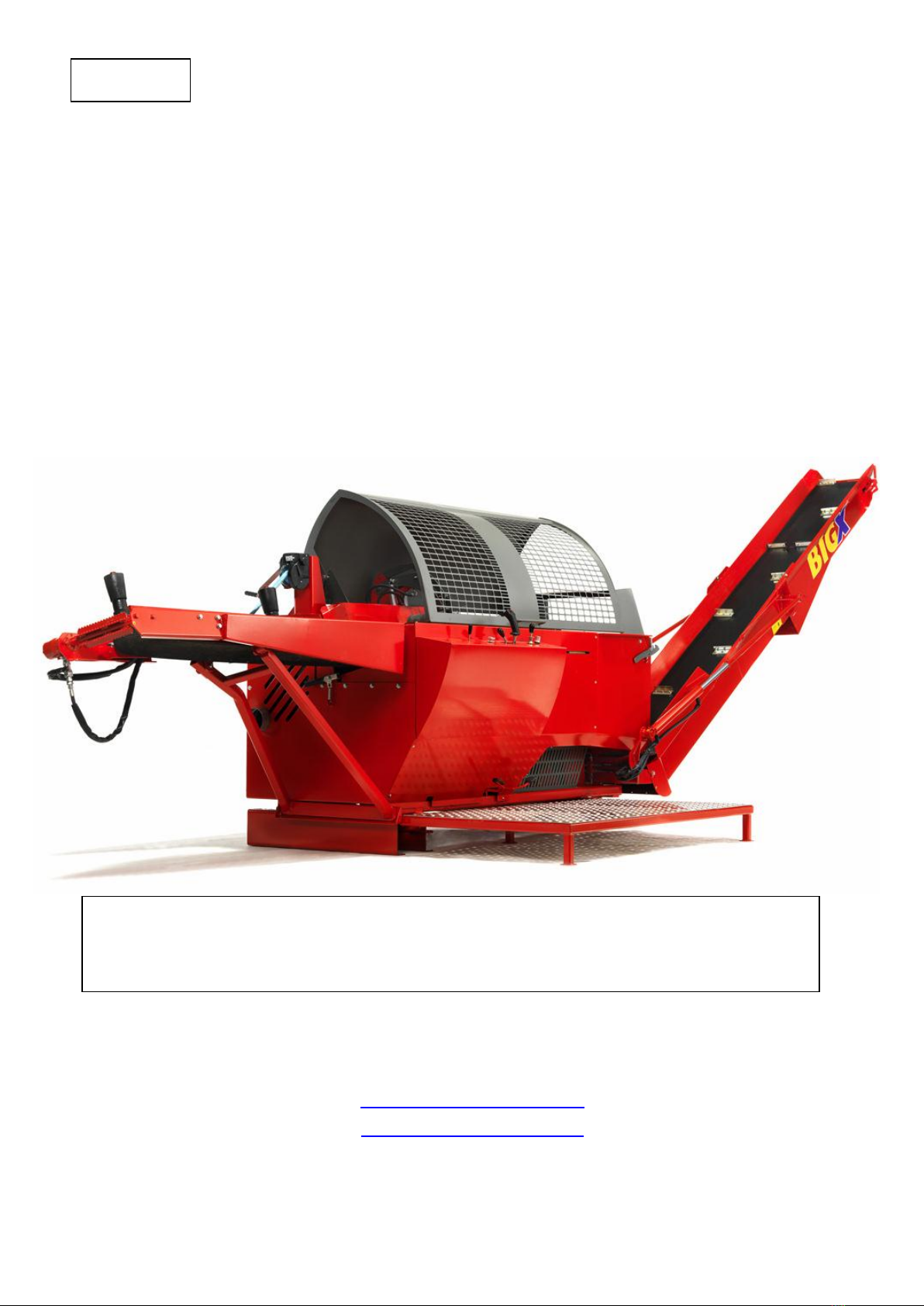
1.2. The machine's purpose of use..................................................................................................................4
1.3. Machine model and basic information ....................................................................................................4
1.4. Operating conditions................................................................................................................................4
1.5. Safety instructions....................................................................................................................................5
1.6. Noise and vibration ..................................................................................................................................5
1.7. Warning symbols ......................................................................................................................................6
2. Reception and assembly ..............................................................................................................8
2.1. Reception inspection................................................................................................................................8
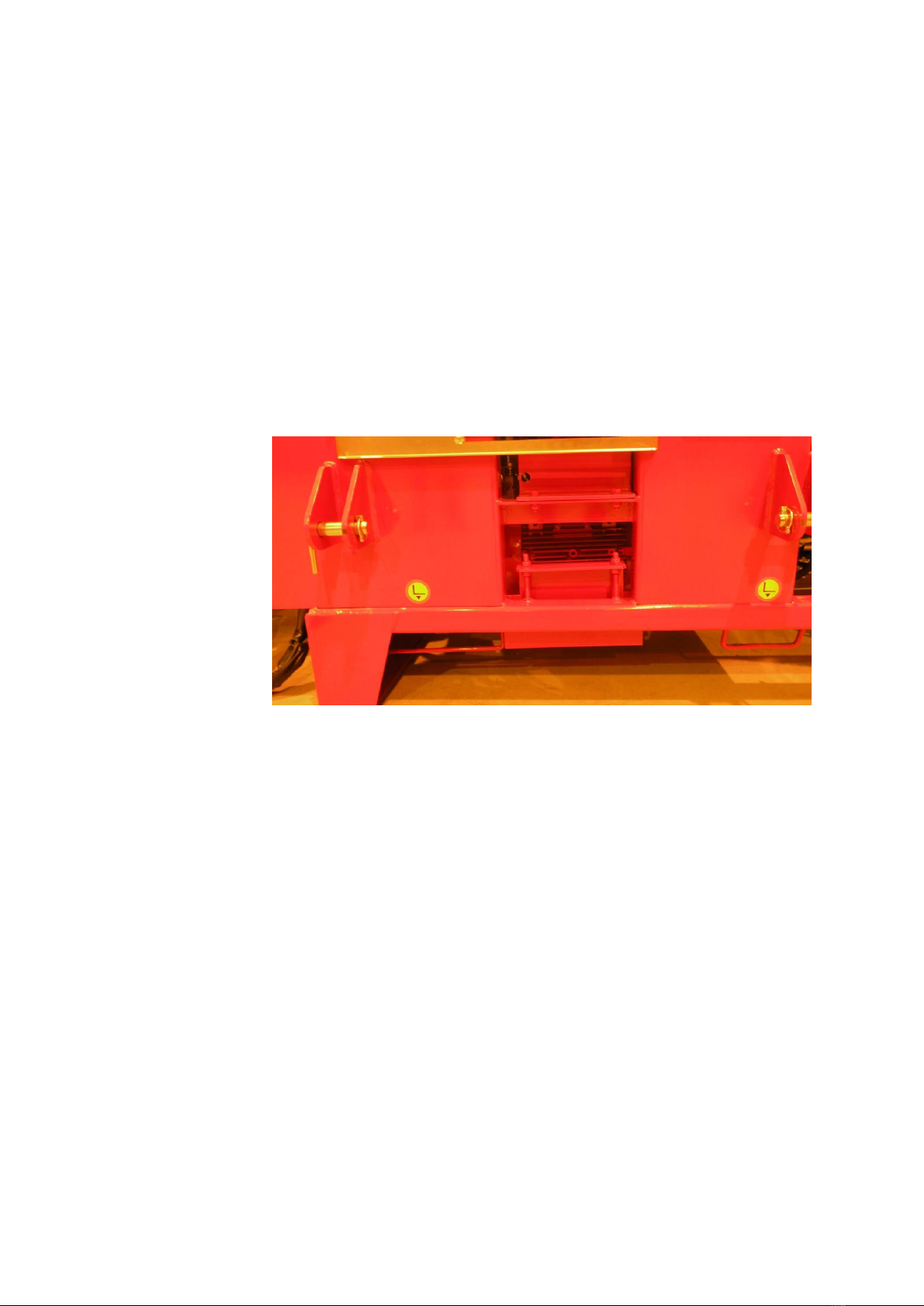
2.2. Lifting and moving the machine...............................................................................................................8
2.3. Main components of the machine ...........................................................................................................8
2.4. Preparing the machine for operation.......................................................................................................9
3. Control functions and preparation ............................................................................................10
3.1. Arranging the machine for operation and transport .............................................................................10
3.1.1. Placing the input conveyor in the operating or transport position ................................................10
3.1.2. Placing the output conveyor in the operating or transport position .............................................10
3.1.3. Placing the working platform in the operating or transport position ............................................11
3.2. Controls ..................................................................................................................................................12
3.2.1. Tractor drive....................................................................................................................................13
3.2.2. Electrical drive.................................................................................................................................13
3.2.3. Adjusting the wood length with the optical measuring device ......................................................15
3.2.4. Using the output conveyor .............................................................................................................15
3.2.5. Adjusting the splitting blade ...........................................................................................................15
3.2.6. Using the dust collector ..................................................................................................................15
4. Operating the machine ..............................................................................................................17
4.1. Test running the machine.......................................................................................................................17
4.2. Placing wood on a log holder .................................................................................................................18
4.3. Feeding and sawing wood ......................................................................................................................18
4.3.1. Blade jamming.................................................................................................................................19
4.3.2. Sawing the last log ..........................................................................................................................19
4.4. Splitting wood.........................................................................................................................................19
4.4.1. Jamming wood on the splitting blade.............................................................................................19
4.4.2. Re-splitting or splitting without cutting..........................................................................................20

3
HakkiPilke 50 Easy Version 1.2 2012
4.4.3. Replacing the splitting blade...........................................................................................................20
4.4.4. Adjusting the length of the splitting motion...................................................................................21
4.5. Using the output conveyor.....................................................................................................................21
4.6. After use .................................................................................................................................................22
5. Maintaining the machine ...........................................................................................................23
5.1. Cutting blade and drive end ...................................................................................................................23
5.1.1. Replacing and tightening the blade chain.......................................................................................23
5.1.2. Replacing the blade flange..............................................................................................................24
5.2. Splitting mechanism ...............................................................................................................................24
5.2.1. Operation of the splitting mechanism ............................................................................................24
5.2.2. Maintaining the splitting mechanism .............................................................................................25
5.3. Replacing and tightening the V-belts .....................................................................................................26
5.4. Changing the oil of the splitter...............................................................................................................26
5.5. Changing the oil of the angle transmission ............................................................................................27
5.6. Conveyor maintenance ..........................................................................................................................28
5.6.1. Replacing and tightening the belt of the input conveyor ...............................................................28
5.6.2. Replacing and tightening the belt of the output conveyor ............................................................28
5.6.3. Replacing the plates of the output conveyor .................................................................................29
6Lubrication..............................................................................................................................................29
7Blade chain lubrication...........................................................................................................................29
8Solenoid and pressure regulating valves................................................................................................29
9Washing and cleaning.............................................................................................................................33
10 Storage................................................................................................................................................33
11 Maintenance table..............................................................................................................................33
12 Failures and remedial measures.........................................................................................................34
13 Electric maps.......................................................................................................................................35
14 Guarantee terms and declaration of conformity ...............................................................................37

4
HakkiPilke 50 Easy Version 1.2 2012
1. General information
1.1. Introduction
The purpose of this manual is to ensure that the machine is used in the manner intended by the manufacturer
with regard to safety. Every person operating the machine or working in close proximity to it must carefully
study this manual.
Operators of the machine are expected to have basic skills in tractor handling, such as utilising the cardan
shaft drive and the tractor's lifting equipment. Before commencing work, operators must also familiarise
themselves with the machine's control and safety equipment, and ensure their proper operation.
Additional information on Maaselän Kone Oy's products is available on our website at www.maaselankone.fi.
Store the manual in the immediate vicinity of the machine.
1.2. The machine's purpose of use
The Hakki Pilke BigX50 log splitter is designed for preparing firewood from pruned wood or logs. The log
splitter must not be used to process any treated wood, such as is found in construction waste. Sand, nails or
other impurities in the wood may damage the machine.
The maximum diameter for wood to be split is 50 cm. This limit may not be exceeded. When estimating the
diameter of the log you are about to cut, note that the shape of the log and other factors, such as branches or
burrs, make the actual diameter larger, and may prevent wood from being fed into the machine. The splitting
groove is designed for logs up to 60 cm in length. Never cut or split logs that exceed the maximum length.
1.3. Machine model and basic information
Model
TR
Combi
Drive
Tractor's cardan shaft (TR)
TR
Electricity
Weight
2,100kg
2,200kg
TR/Electrical drive
min 35hp / max 500 rpm 15kW (min 32 A fuse)
Height/width/length
in the transport position 2,900/3,100/1,520 (mm)
Input/output conveyor
2,850/4,000 (mm)
Blade flange/chain
Flange: 20’ groove 1.6 mm chain: 71 loops, pitch 0.404’
Max wood diameter
50 cm
Max wood length
Processed firewood: max 60 cm / min 17 cm
The machine's serial number, manufacturing date, weight, operating voltage (electrically-operated machine)
and model are indicated on the type plate located on the left-hand side of the machine from the operator's
perspective.
1.4. Operating conditions
The temperature range within which the machine can be operated is -20 –+30 °C. In the winter, the
operator must ensure that there is no risk of slipping in the working area.
The working area must be even and clear of unnecessary items. No extra or unauthorised persons are
allowed in the working area. The working area must also be sufficiently illuminated.

5
HakkiPilke 50 Easy Version 1.2 2012
The machine must not be used indoors.
1.5. Safety instructions
This machine is intended to be used by one operator. The danger zone around the machine is 10 m.
Persons under 18 years of age may not operate the machine.
The operator must ensure that using the machine does not cause danger to others and that no extra or
unauthorised persons are within the danger zone.
Do not operate the splitter while under the influence of alcohol or drugs, or if you are tired.
Do not use the machine if you have not familiarised yourself with this instruction manual.
The machine has been designed solely for making firewood.
The splitter must be arranged for transport whenever it is moved. When transporting the machine on
a public road, it must be equipped with additional lights.
The operator is not permitted to modify the structure or operation of the machine, or to remove
protective equipment.
Operators must wear ear protection, sufficiently tight-fitting work clothing, work gloves, protective
goggles and safety footwear.
Before starting up the splitter, the operator must ensure that the machine and its shields are intact.
When powering the machine with a tractor, the operator must ensure that the cardan shaft is
undamaged and that the rpm range is correct. The machine must be attached to the tractor's lifting
equipment when operating.
Before starting up the splitter, the operator must ensure that all the control and safety devices are
functional.
When cleaning or maintaining the machine, it must be disconnected from its power source.
1.6. Noise and vibration

6
HakkiPilke 50 Easy Version 1.2 2012
1.7. Warning symbols
DANGER ZONE
BEWARE OF THE CHAIN
ONLY ONE PERSON AT A TIME IN
THE WORK AREA
SHUT DOWN BEFORE
MAINTENANCE
BEWARE OF MOVING PARTS
RISK OF ENTANGLEMENT WITH
THE CARDAN SHAFT
RISK OF CRUSHING
DO NOT GO UNDER THE
CONVEYOR
MAX CONVEYOR TILT ANGLE
BEWARE OF THE SPLITTING
BLADE

7
HakkiPilke 50 Easy Version 1.2 2012
READ THE MANUAL BEFORE USE
USE PROTECTIVE EQUIPMENT
ALWAYS GRAB A LOG BY THE SIDES
MAX RPM
Scale
HYDRAULIC OIL
LEFT ROTATION
CHAIN OIL
LIFTING POINT FOR FORKLIFT
EMERGENCY STOP

8
HakkiPilke 50 Easy Version 1.2 2012
2. Reception and assembly
2.1. Reception inspection
Dispose of the machine’s packaging in a environmentally friendly manner. Ensure that the machine's splitting
groove contains the components of the input conveyor's additional roller (parts according to Figure 4 in
Section 2.4), the lifting winch for the splitting blade as well as more than one splitting blade as possible
additional accessories.
Check that the splitter has not sustained any damage during transit, and ensure that all necessary parts are
included in the package. If you encounter defects or damage, contact the retailer immediately.
2.2. Lifting and moving the machine
When moving the
machine, make sure that
the moving and lifting
capacity of your tractor or
forklift is sufficient for the
machine’s weight. Only
lift the splitter by the
indicated lifting points or
with the lifting equipment
of a tractor.
Note! If you move the
machine with a forklift,
detach the working
platform.
Figure 1. Lifting points
When connecting the machine to a tractor's lifting equipment, the tractor cabin must be free of people in
order to prevent any accidental contact with the controls. Check all connecting devices of the tractor and log
splitter before connecting them. Never use faulty equipment. The pins that are used to connect the pushbars
and drawbars to the log splitter must be of the correct size, and the appropriate locking pins must be used to
ensure that they remain secure.
The splitter must be placed in the transport position if it is to be moved more than 5 metres. Exercise extreme
caution when moving the machine in the operating position. Lower the machine to the ground when you stop.
Note! Incorrect lifting may cause a hazardous situation or damage the machine.
2.3. Main components of the machine
The Hakki Pilke BigX 50 is a log splitter with fully hydraulic controls. In other words, all of the machine's
functions are controlled hydraulically with operating levers on the machine's control panel. The guard of the
cutting and splitting section is interlocked to the machine's operation: opening the guard stops all functions.

9
HakkiPilke 50 Easy Version 1.2 2012
A. Input conveyor
B. Cutting and
splitting unit
C. Control unit
D. Output
conveyor
Figure 2. Main components of the machine.
2.4. Preparing the machine for operation
1. Connect the lifting winch of the
splitting blade to the link
bushing on the side of the
splitting groove, as shown in
Figure 3.
2. Install the input conveyor's
auxiliary roller according to the
instructions below.
3. Finally, ensure that the splitting
groove is free of any extraneous
items or debris.
Figure 3. Installing the lifting winch for the splitting blade
Figure 4. Installing the auxiliary input roller
1. Install the motor
flange on the
frame of the
conveyor, as
shown in the
figure, and lock it
in place with three
bolts.
2. Check that the motor's
bayonet contact is
firmly attached.
Note! The bayonet
contact supplies
hydraulic power to the
input conveyor
extension, if one is
installed.
3. Install the auxiliary
roller and its
fastening flange on
the shaft of the
hydraulic motor.
4. Lock the flange and
roller on the
conveyor frame
with three bolts.

10
HakkiPilke 50 Easy Version 1.2 2012
3. Control functions and preparation
3.1. Arranging the machine for operation and transport
Before arranging the machine for transport, ensure that the operating conditions detailed in Section 1.4 are
met and review the safety instructions in Section 1.5.
Note! Inspect and clean the machine according to Sections 4.3 and 5.8 before arranging it for transport.
3.1.1. Placing the input conveyor in the operating or transport position
Place the input conveyor in the operating position
as follows:
1. Ensure that sufficient room is available to
lower the input conveyor (approx. 2 m).
2. Release approx. 15 cm of lifting strap from
the winch A.
3. Release the conveyor lock B and push the
conveyor down until the lifting strap
tightens.
4. Use the winch to lower the input conveyor
down onto its support C. The support must
fit into the intended slot D in the frame.
When placing the input conveyor in the transport
position, use the winch to lift the conveyor up, and
ensure that the locking latch locks it in place.
Figure 5. Lowering the input conveyor
3.1.2. Placing the output conveyor in the operating or transport position
Place the output conveyor in the operating position as follows:
Note! Two people are required to turn the conveyor.
1. Ensure that sufficient room is avaible to lower the output conveyor.
2. Use the control H in Figure 9 of Section 3.2 (anti-clockwise) to make sure that the conveyor is
stopped, and start the machine.
3. Keep the lock A open, and move the control E in Figure 9 of Section 3.2 to the right to
hydraulically lower the output conveyor to its lowest position.
4. Turn the upper section of the conveyor to the operating position with the handles C at the
upper end. Two people are required to turn the conveyor.
5. Turn the output conveyor's support bar B to the side.
6. Lift the conveyor hydraulically, and use the lock D on the bottom of the conveyor to lock the
upper section of the output conveyor in the operating position.

11
HakkiPilke 50 Easy Version 1.2 2012
Figure 6. Placing the conveyor in the operating or transport position
Place the output conveyor in the transport position as follows:
1. Use the control H in Figure 9 of Section 3.2 to stop the conveyor.
2. Release the lock D holding the upper section of the conveyor in place, and hydraulically lower
the conveyor to the lowest position with the operating lever E in Figure 9.
3. Position the support bar B over the belt, and fold the upper section of the conveyor onto the
lower section with the handle C.
4. Turn the conveyor to the middle position.
Use the control lever to hydraulically lift the conveyor until it locks into the raised position. Ensure that
the lock A connects firmly.
3.1.3. Placing the working platform in the operating or transport
position
1. Ensure that there is sufficient room for the working platform, and that the ground is
sufficiently even under the legs of the platform.
2. Pull the platform to the working position.
Note! Once the working platform is installed, the splitter can only be transported by means
of three-point attachment.
Figure 7. The working platform in the transport
position
Figure 8. The working platform in the
operating position

12
HakkiPilke 50 Easy Version 1.2 2012
3.2. Controls
Figure 9. The machine's controls
Names and functions of the controls in Figure 9
A. Control for additional hydraulics. For example, a log
holder.
B. Adjustment for the downward pressure of the
cutting flange
Turning the knob clockwise increases the
speed of the motion, and vice versa.
C. Height adjustment for the cutting blade
D. Joystick –control
Input conveyor control –upper right and
upper left
Cutting control –down
Splitting –release from the bottom position
Wood press: button A in Figure 10
Blade chain activation: button B in Figure 10
E. Lifting, lowering and turning the output conveyor
F. Reset pedal for splitting
G. Activation pedal for splitting
H. Adjustment for the running speed of the output
conveyor
Turning the knob anti-clockwise increases the
speed.
The conveyor slows down and eventually stops
when the knob is turned clockwise.
Figure 10. Joystick

13
HakkiPilke 50 Easy Version 1.2 2012
3.2.1. Tractor drive
A tractor-powered splitter must be
connected to a three-point lifting device and
the tractor's cardan shaft. To connect the
machine to the cardan shaft, you need to
move the protective cover A of the electrical
connector and angle transmission into a
position where it covers the electrical
connector.
Connecting the cardan shaft is a task for only
one person. The tractor cabin must be free
of people in order to prevent accidental
contact with the controls while the log
splitter is being connected to the tractor.
Check all connecting devices of the tractor
and log splitter before connecting them.
Never use faulty equipment.
Figure 11. Powering the machine with a tractor
When utilising the cardan shaft, observe any instructions provided by the shaft's manufacturer. The splitter
requires 15 kW of power, which must be taken into account with regard to the capacity of the cardan shaft.
The cardan shaft must be at least a class 5 shaft. Check that the shaft is properly locked to the splined shaft of
the angle transmission. The chain that prevents the guard from rotating must be attached to point B of the
angle transmission's base. If necessary, the cardan shaft can be suspended from hook C. Finally, ensure that all
the connections are safe and secure! Never use a damaged or unprotected cardan shaft.
In a tractor-powered machine, the connector D of the optical measuring device must be connected to the
tractor's socket. The connector for the device is located at the back of the splitter.
Note! Tractor-powered splitters must be attached to the tractor's lifting equipment.
Note! The starter (Figure 14) only functions when the machine is powered by electricity.
3.2.2. Electrical drive
An electrically-powered splitter functions with
a power of 15 kW. The fuse must be at least 32
A. The electrical cable, in turn, must be at least
5 x 6 mm². In order to connect the cable, move
the protective cover B of the electric connector
A and angle transmission into a position where
it covers the angle transmission.
Figure 12. Powering the machine with electricity

14
HakkiPilke 50 Easy Version 1.2 2012
In an electrically-powered machine, the
connector of the optical measuring device must
be connected to the socket on the side of the
machine.
The splitter can be activated with the starter in
the control panel at the front of the machine. If
the electric motor rotates in the wrong
direction (i.e. the machine makes an abnormal
noise and the hydraulic functions are
inoperable), the current phase is incorrect. We
recommend using an extension cord that
allows you to switch the current phase or an
adapter that can switch the phase.
Note! If the extension cord does not have a
phase switch, the electrical work related to
changing the phase must be performed by an
electrician.
Figure 13. Connector of the optical measuring
device
Figure 14. Starter
Figure 14 b.

15
HakkiPilke 50 Easy Version 1.2 2012
3.2.3. Adjusting the wood length with the optical measuring device
The Hakki Pilke BigX 50 splitter is
equipped with an optical wood
measuring device. The device
automatically stops the input conveyor
when a piece of wood has been fed to
the desired length. The sensor of the
optical measuring device can be freely
adjusted to a position that is 20–60 cm
from the cutting flange.
Adjust the log guide to the same
measurement as the measuring device.
The log guide should be at a distance of
approx. 5 cm from the log during cutting.
Note! The error margin for the optical
measuring device is +/- 0.75 cm.
Figure 15. Log length adjustment
3.2.4. Using the output conveyor
The output conveyor can be controlled with the controls E and H in Figure 9. Use the control E to select the
direction and elevation of the conveyor. The control H can be used to freely adjust the running speed of the
conveyor. The speed can be decreased until the conveyor stops. Always stop the conveyor when placing it in
the operating or transport position.
3.2.5. Adjusting the splitting blade
The splitting blade can be controlled hydraulically by moving the control lever C in Figure 9 up or down. Logs
should always be as centred as possible when passing the blade in order to keep the size of the firewood
consistent.
When wood is stuck on the blade, the blade can be lowered in increments of approx. 1–2 cm. The blade can
be driven to the lowest position by raising the blade and clearing the space under the blade. The machine
must be shut down and disconnected from its power source for the duration of the cleaning.
3.2.6. Using the dust collector
The standard equipment of the splitter includes a hydraulic dust collector. It allows you to collect sawdust for
any purposes you may wish to use it. The dust collector activates automatically when the machine starts up.

16
HakkiPilke 50 Easy Version 1.2 2012
If you are not using a dust pipe with the dust collector,
make sure that the safety grill is in front of the pipe, as
indicated in the figure.
When using a dust pipe, attach the safety grill with
only one bolt and turn it to a horizontal position
as shown in the figure.
You can disable the dust collector as follows:
1. Remove the cover plate and turn the dust
collector to the maintenance position as shown
in the figure.
3. Turn the lever in the figure to the OFF position to
stop the dust collector motor.

17
HakkiPilke 50 Easy Version 1.2 2012
2. Turn the dust collector back to the working
position and reattach the cover plate.
4. Remove the dust plate and install the safety
grill as indicated in the figure.
4. Operating the machine
4.1. Test running the machine
The machine must not be used before carrying out a test run and testing all the functions. Both the test run
and testing can only be performed by a person who has studied the machine's manual.
Before the test run, all the components of the log splitter must be checked. If any faults or wear that may
affect the safe use of the machine are discovered, the log splitter must not be used until the faulty or worn
component is replaced and safe use can be ensured.
1. Check that the guard of the log splitter's cutting and splitting section is down.
2. Check that the input and output conveyors are in the operating position.
3. Ensure that the splitting groove is empty.
4. Make sure that you are familiar with the functions of the splitter's controls. If necessary, refer to
Section 3.2.
5. Activation
a. Tractor-powered: Insert the connector of the optical measuring device into the tractor's
electrical socket. Start the tractor and connect the output, starting with a slow speed and
increasing the speed to a maximum of 500 rpm.
b. Electrically-powered: Connect a cable to the log splitter's socket, start the splitter by pressing the
start button and wait a moment. This activates the electric motor at full speed.
6. Start the cutting motion with the joystick D in Figure 9. The cutting motion must be normal when the
blade returns up.

18
HakkiPilke 50 Easy Version 1.2 2012
7. Do the following to ensure that the blade chain lubrication functions automatically: (If necessary, see
Section 5.6.1)
a. Use the joystick D in Figure 9 to perform a few sawing motions without sawing any actual wood.
b. Shut down the splitter and disconnect it from its power source.
c. Open the guard and see if the blade chain has been supplied with oil.
8. In especially cold weather, the cutting motion can be slow at first. If this is the case, repeat the motion
with the splitting pedal (Figure 9, pedal G), until the oil warms up and the speed returns to normal.
9. Ensure that pressing the button A of the joystick in Figure 10 releases the wood press and that pressing
the button B of the joystick starts the blade chain.
10. Start the splitting motion with the splitting pedal (Figure 9, pedal G), and stop it by opening the guard
of the cutting and splitting section.
11. Ensure that the splitting beam returns to the initial position by holding down the pedal F (Figure 9).
12. Start the splitting motion by briefly pressing the pedal G (Figure 9).
13. Test run the input conveyor's feed and return motion with the joystick D in Figure 9.
14. Test run the lifting motion of the hydraulic wood press by moving the joystick D in Figure 9 forward
and, at the same time, pressing the joystick button A (Figure 10).
15. Start the output conveyor by using the control H in Figure 9 to adjust the speed to an appropriate
level.
If the machine presents a fault during the test run, determine the reason and take remedial action as
necessary. The machine must be shut down and disconnected from the power source for the duration of the
diagnostics and repairs.
4.2. Placing wood on a log holder
We recommend auxiliary devices, such as a Woodran 471/Woodran 472 log holder or the hydraulic log hoist
Woodlift 471. If a log holder is not attached to the splitter, the maximum allowed log length is 4.5 m. Always
lift and place wood on the input table in a safe manner that does not endanger the operator.
Note! Placing logs directly on the input table with a loader is strictly prohibited.
Note! Ensure that the log's centre of gravity stays on the conveyor.
4.3. Feeding and sawing wood
The input conveyor feeds the wood to be processed into the splitter. Push the joystick D in Figure 9 of Section
3.2 to the upper right to feed wood into the machine. The feed can be cancelled by pushing the joystick to the
upper left.
When feeding wood, ensure that the log does not present a risk of getting caught between the log and the
machine, for example due to the shape of the wood. Do not use your hand to guide the log into the cutting
section. Adjust the optical measuring device to the desired measurement and start the output conveyor.
1. Choose the log to process. Note that the maximum log diameter is 50 cm. The knottiness and shape of
the wood increase the diameter.
2. Raise the hydraulic wood press by pressing down the button A (Figure 10) of the joystick D (Figure 9)
and by pushing the control lever forwards. Use the joystick D to feed wood into the machine with the
input conveyor. Moving the joystick to the upper right activates the feed. The optical measuring
device stops the conveyor when the desired length has been fed.
3. When the log stops, lock it in place with the wood press. The wood press is activated automatically
when you lower the cutting flange with the joystick D in Figure 9 (also in Figure 10).

19
HakkiPilke 50 Easy Version 1.2 2012
4. Cut the log by pressing the button B (Figure 10) of the joystick D. The button activates the blade chain.
Then, lower the cutting flange by moving the joystick D backwards.
5. Return the cutting flange to the raised position by pushing the joystick D forwards, which
automatically stops the splitting function.
Note! Ensure that the wood being fed does not collide with a lowered wood press or flange.
4.3.1. Blade jamming
Ensure that the cutting flange's downward motion has not been adjusted (flow valve B in Figure 9 of Section
3.2) to be too fast in proportion to the size of the wood.
If the cutting blade is jammed in the wood, stop sawing and try again in another position. If the cut is
misaligned because the flange drags to one side, the sharpness of the blade chain must be checked. A chain
that is not evenly sharp always drags to the duller side, which makes cutting a thicker log impossible. On the
other hand, sawing with an evenly dull chain is inefficient, and the chain must be sharpened or replaced (see
Section 5.1.1).
4.3.2. Sawing the last log
When sawing wood, the second to last piece should be sawed in such a way that the remaining piece is of a
sufficient length. This ensures that the wood will stay firmly under the hydraulic wood press and that the
sawing will be steady and safe.
Drive the last wood piece directly into the splitting section, and start the splitting process with the pedal G in
Figure 9.
4.4. Splitting wood
The splitting beam performs the splitting motion automatically whenever the cutting flange is lowered all the
way down (control D in Figure 9 of Section 3.2 up/down) and raised back up again.
You can also start the splitting motion with the pedal (G in Figure 9) by briefly pressing it. Do not keep the
pedal pressed for long –about one second is enough. The foot pedal is primarily intended for splitting the last
piece of wood. By using the pedal, the operator has no need to unnecessarily lower the cutting flange.
Instead, the splitting can be activated more quickly and easily with the pedal.
If there is a problem with splitting and the splitting beam must be prematurely returned to the initial position,
open the guard of the cutting and splitting section, which stops the splitting function. Then, press the pedal F
in Figure 9 down and hold it down until the beam has fully returned to the initial position.
4.4.1. Jamming wood on the splitting blade
If a piece of wood gets jammed on the splitting blade in a situation where the splitting force is insufficient to
push the piece past the blade, do the following:
1. Restore the splitting beam to the initial position with the reverse pedal (pedal F in Figure 9).
2. Lift the splitting blade to the highest possible position (control C in Figure 9).
3. Cut a sufficiently thick piece of wood (approx. 20–25 cm) into the splitting groove, and activate the
splitting process with the pedal (G in Figure 9). The new piece will then push the jammed piece past
the blade.
4. Lower the blade by approx. 10 cm and repeat step 3. Repeat step 4 until the jammed wood has
passed the blade piece by piece.

20
HakkiPilke 50 Easy Version 1.2 2012
4.4.2. Re-splitting or splitting without cutting
1. Raise the guard of the cutting and splitting section.
2. Place the log you want to split in the splitting groove.
3. Close the guard of the cutting and splitting section.
4. Start the splitting process with the activation pedal (G in Figure 19).
As necessary, the above procedure can be used to split wood without cutting it.
4.4.3. Replacing the splitting blade
Exercise extreme caution when handling the blade, and use protective gloves. The blade is sharp and weighs
approx. 85 kilos. Ensure that the lifting winch for the splitting blade has been installed according to Section
2.4.
1. Lower the splitting blade all the way
down, which releases it from the
adjusting joint.
2. Shut down the splitter and disconnect it
from its power source.
3. Open the protective mesh and move
the cover plate A aside.
4. Turn the winch frame onto the splitting
blade, and release wire from the winch.
5. Attach the lifting hook to the lifting
point B.
6. Use the winch to lift up the splitting
blade, and lock the winch reel.
7. Turn the winch so that you can lower
the splitting blade on the ground, next
to the machine.
8. Release the winch lock, and use the
winch to lower the blade.
9. Install a new splitting blade by reversing
the above steps.
Figure 16. Replacing the splitting blade
Table of contents
Other Hakki Pilke Log Splitter manuals
Popular Log Splitter manuals by other brands

Wallenstein
Wallenstein WX410 Operator's manual

MADER
MADER LSE2203 Operator's manual

POWER DOG
POWER DOG QUICK SPLIT 24 owner's manual

Scheppach
Scheppach HL1100GE Translation from the original instruction manual

Iron & Oak
Iron & Oak BH2W2016GX owner's manual

BE Ag & Industrial
BE Ag & Industrial Agri Ease BE-LS25TLE5GC owner's manual