Hakki Pilke Raven User manual

HAKKI PILKE RAVEN TRANSLATION VERSION 1-2015
FIREWOOD PROCESSOR
–Instructions for assembly, operation and maintenance
–EC Declaration of Conformity
–Safety instructions
–Guarantee terms
Valimotie 1, FI-85800 Haapajärvi, FINLAND
Tel. +358 8 772 7300, Fax +358 8 772 732
ENGLISH
THE OPERATOR MUST READ AND UNDERSTAND THESE INSTRUCTIONS
BEFORE OPERATING THE FIREWOOD PROCESSOR.

HAKKI PILKE RAVEN TRANSLATION VERSION 1-2015
Table of contents
1 General information ...................................................................................................................................4
1.1 Introduction....................................................................................................................................... 4
1.2 Purpose of use ................................................................................................................................... 4
1.3 Machine models and basic information ............................................................................................ 4
1.4 Operating conditions ......................................................................................................................... 5
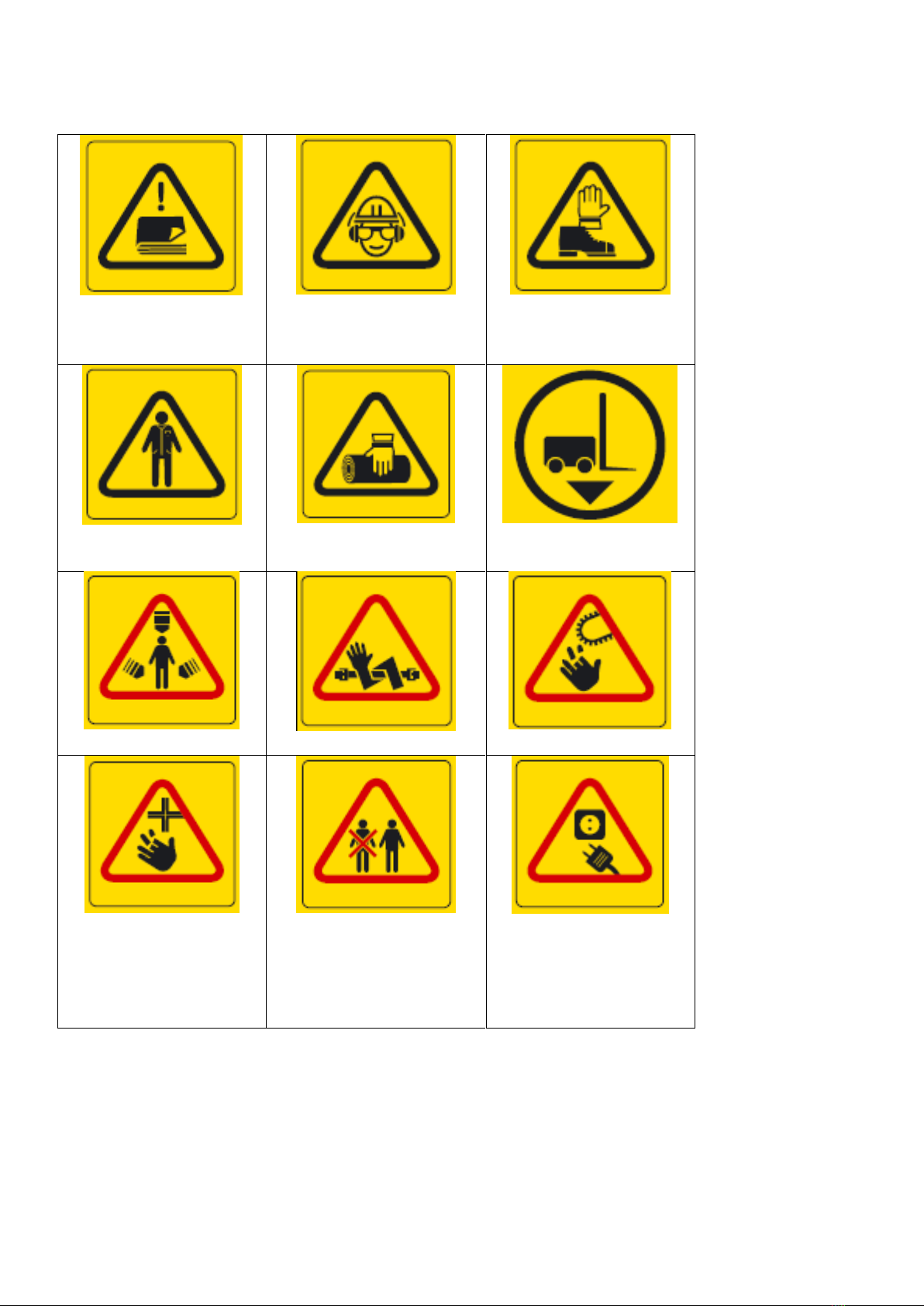
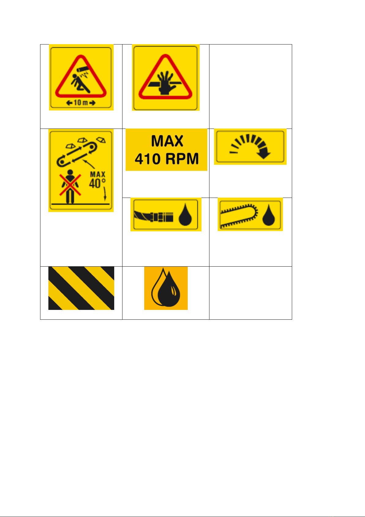
1.5 Safety instructions ............................................................................................................................. 5
1.6 Noise and vibration............................................................................................................................ 5
2 Setting up the machine for operation and transport .................................................................................8
2.1 Delivery inspection ............................................................................................................................ 8
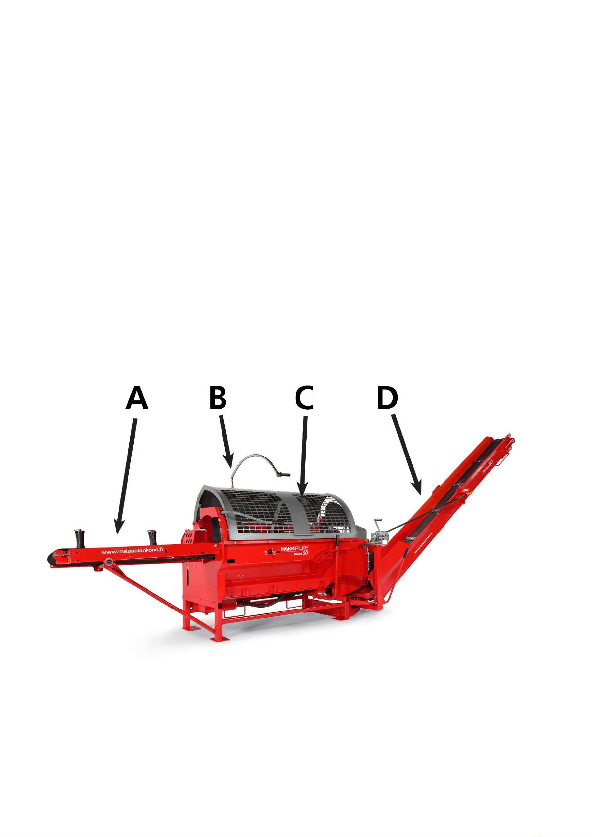
2.2 Main components of the machine .................................................................................................... 8
2.3 Arranging the machine for operation and transport......................................................................... 9
2.4 Connecting the machine to a power source.................................................................................... 13
2.5 Lifting and moving the machine ...................................................................................................... 15
2.6 Additional hydraulics connections (accessories)............................................................................. 16
2.7 In-feed conveyor belt speed control (accessory) ............................................................................ 16
3 Operating the machine............................................................................................................................ 17
3.1 machine controls and functions ...................................................................................................... 17
3.2 Performing a test run on the machine ............................................................................................ 18
3.3 Wood feeding, cutting and splitting ................................................................................................ 19
3.4 Using the output conveyor.............................................................................................................. 20
3.5 After use .......................................................................................................................................... 22
4 Maintenance and adjustment of the machine........................................................................................ 22
4.1 Disconnecting the machine from its power source......................................................................... 22
4.2 Adjusting the log length................................................................................................................... 23
4.3 Height adjustment of the splitting knife.......................................................................................... 24
4.4 Replacing the splitting knife ............................................................................................................ 25
4.5 Adjusting the tightness and alignment of the output conveyor belt .............................................. 26
4.6 Cutting blade and drive end ............................................................................................................ 27
4.7 Changing the oil............................................................................................................................... 29
4.8 Changing the oil of the multiplier gear............................................................................................ 30
4.9 Conveyor maintenance.................................................................................................................... 30
4.10 Lubrication....................................................................................................................................... 32
4.11 pressure regulating valves............................................................................................................... 36
4.12 Washing and cleaning...................................................................................................................... 37
4.13 Storage............................................................................................................................................. 37

HAKKI PILKE RAVEN TRANSLATION VERSION 1-2015
4.14 Maintenance table ...........................................................................................................................37
5 Failures and remedial measures ..............................................................................................................38
5.1 Jamming of the cutting blade...........................................................................................................39
5.2 Jamming of the wood on the splitting knife.....................................................................................39
6 Hydraulics diagram (tractor-operated machine)......................................................................................40
7 Guarantee terms and declaration of conformity .....................................................................................41
EC Declaration of Conformity for the machine ................................................................................................42

HAKKI PILKE RAVEN TRANSLATION VERSION 1-2015
1 General information
1.1 INTRODUCTION
The purpose of this manual is to ensure that the machine is used in the manner intended by the manufac-
turer, taking safety into consideration. Everyone operating the machine or working in close proximity to it
must study this manual carefully.
Operators of the machine are expected to have basic skills in tractor handling, such as utilising the cardan
shaft drive and the tractor's lifting equipment. Before commencing work, operators must also familiarise
themselves with the machine's control and safety equipment, and ensure their proper operation.
Additional information on Maaselän Kone Oy's products is available on our website at
www.maaselankone.fi.
Keep this manual in the immediate vicinity of the machine.
1.2 PURPOSE OF USE
The Hakki Pilke Raven firewood processor is designed for the preparation of firewood from pruned wood or
logs. The firewood processor must not be used to process any treated wood, such as is found in construc-
tion waste, for example. Sand, nails or other impurities in the wood may damage the machine.
The maximum diameter of the logs to be processed is 30 cm. This limit must not be exceeded. When esti-
mating the diameter of the log you are about to cut, note that the shape of the log and other factors, such
as branches and burrs, make the actual diameter larger, and may prevent the log from being fed to the
machine. Do not split logs that exceed 50 cm in length.
1.3 MACHINE MODELS AND BASIC INFORMATION
Model
TR
Electrical
Driving power
Tractor's cardan shaft (TR)
Electric motor
Weight
710 kg
750 kg
TR/Electrical drive
min 20 hp/max 410 rpm 5.5 kW
Height/width/length
in transport position
Transport position 251/136/262 (cm)
Input/output conveyor
220/400 (cm)
Saw bar/chain
bar: 15” groove 1.5 mm chain: 66 loops, pitch 0.325”
Max log diameter
30 cm
Max/min log length
Log max 50 cm; min 17 cm
The machine’s serial number, date of manufacture, weight, operating voltage (electrically operated ma-
chines) and model are indicated on the grey type plate located on the machine frame below the locking
latch of the output conveyor, on the right side of the operator.

HAKKI PILKE RAVEN TRANSLATION VERSION 1-2015
1.4 OPERATING CONDITIONS
The temperature range within which the machine can be operated is -20 to +30°C. In the winter, the opera-
tor must ensure that there is no risk of slipping in the working area.
The working area must be level and clear of unnecessary items. No unauthorised persons must en-
ter the working area. The machine may only be used in sufficient lighting conditions. These re-
quirements must be met for the entire duration of the work.
The machine may not be used indoors.
1.5 SAFETY INSTRUCTIONS
This device is designed to be operated by only one operator. The danger zone is 10 m from the ma-
chine.
Persons under 18 years of age may not operate the machine.
The operator must ensure that use of the device does not cause danger to others and that there
are no unauthorised persons in the danger zone.
The machine may not be operated while under the influence of alcohol or other drugs, or when
tired.
The machine may not be operated unless the operator has familiarised themselves with this in-
struction manual.
The machine has been designed solely for making firewood.
The machine must be placed in the transport position whenever it is moved. When transporting the
machine on a public road, it must be equipped with additional lights.
The operator is not permitted to modify the structure or operation of the machine, or to remove
protective equipment.
The operator must wear ear protectors, sufficiently tight-fitting work clothing and gloves, protec-
tive goggles and safety footwear.
Before starting up the machine, the operator must ensure that the machine and its guards are in-
tact.
When powering the machine with a tractor, the operator must ensure that the cardan shaft is un-
damaged and that the rpm range is correct. The machine must be attached to the tractor's lifting
equipment during operation.
Before starting up the firewood processor, the operator must ensure that all the control and safety
devices are functional.
When cleaning the machine or carrying out any maintenance, it must be disconnected from its
power source.
Note! Do not leave a running machine unsupervised!
1.6 NOISE AND VIBRATION
The vibration values do not exceed 2.5 m/s2.

HAKKI PILKE RAVEN TRANSLATION VERSION 1-2015
Warning symbols
READ THE MACHINE’S MANUAL
BEFORE OPERATING THE MA-
CHINE.
WEAR EYE AND EAR PROTECTION.
WEAR SAFETY FOOTWEAR AND
WORK GLOVES.
DO NOT WEAR ANY LOOSE
ITEMS OF CLOTHING.
ALWAYS GRAB THE PIECE OF
WOOD OR LOG FROM THE SIDE.
LIFTING POINT FOR FORKLIFT.
BEWARE OF MOVING PARTS.
BEWARE OF THE CARDAN SHAFT.
BEWARE OF THE CHAIN.
BEWARE OF THE KNIFE.
ONLY ONE PERSON MAY OPERATE
THE MACHINE.
DISCONNECT THE POWER SUP-
PLY BEFORE CARRYING OUT
MAINTENANCE PROCEDURES.

HAKKI PILKE RAVEN TRANSLATION VERSION 1-2015
THE DANGER ZONE IS 10 M
FROM THE MACHINE.
RISK OF CRUSHING
THE MAXIMUM PERMITTED
ANGLE OF THE CONVEYOR IS
40°. DO NOT PASS UNDER THE
CONVEYOR.
THE MAXIMUM SPEED FOR THE
CARDAN SHAFT IS 410 RPM.
THE ROTATION DIRECTION IS IN
THE DIRECTION OF THE ARROW.
HYDRAULIC OIL
SAW CHAIN OIL
DANGER ZONE
LUBRICATION POINT

HAKKI PILKE RAVEN TRANSLATION VERSION 1-2015
2 Setting up the machine for operation and transport
2.1 DELIVERY INSPECTION
Dispose of the machine’s packaging material in an environmentally friendly manner.
Check that the machine has not sustained any damage during transit, and ensure that all necessary parts
are included in the package. In the event of any defects or damage, contact the retailer immediately.
2.2 MAIN COMPONENTS OF THE MACHINE
The main components of the Hakki Pilke Raven firewood processor are presented in the figure below.
A. Input conveyor
B. Control unit
C. Cutting and
splitting unit
D. Output convey-
or
Figure 1. Main components of the machine

HAKKI PILKE RAVEN TRANSLATION VERSION 1-2015
2.3 ARRANGING THE MACHINE FOR OPERATION AND TRANSPORT
Before arranging the machine for operation, ensure that the operating conditions detailed in Section 1.4
are met and review the safety instructions in Section 1.5.
Note! Inspect and clean the machine before setting it up for transport!
Placing the output conveyor in the operating or transport position
Figure 2.
Figure 3.

HAKKI PILKE RAVEN TRANSLATION VERSION 1-2015
Place the input conveyor in the operating position as follows:
1. Ensure that sufficient room is available to lower the input conveyor (approx. 2 m).
2. Remove the other end of the support leg holder C from the lug (Figure 2).
3. Release the lock by removing pin A and turning locking latch B out of its slot (Figure 3).
Note! At the same time, hold the end of the input conveyor with your left hand!
Figure 4.
4. Lower the input conveyor with your left hand while simultaneously using your right hand to guide support leg D
into slot E (Figure 4).
When placing the input conveyor in the transport position, lift the conveyor to the upper position,
turn locking latch B into its slot and insert pin A (Figure 3). Use holder C to lock the support leg in
place (Figure 2).

HAKKI PILKE RAVEN TRANSLATION VERSION 1-2015
Placing the output conveyor in the operating or transport position
Place the output conveyor in the operating position as follows:
1. Ensure that there is sufficient room for
opening the output conveyor.
2. Turn off the machine and disconnect it
from the power source.
3. Keep lock A (Figure 5) open and lower
the output conveyor using a winch to its
lowest position.
4. Turn the upper section of the conveyor
into the operating position using handle
B (Figure 6).
5. Turn support bar C on the output con-
veyor belt (Figure 7) to the side.
Figure 5.
Figure 6.
Figure 7.

HAKKI PILKE RAVEN TRANSLATION VERSION 1-2015
6. Use a winch to lift the conveyor to the
desired angle (max 40°) and lock the
upper section of the output conveyor to
the operating position using lock D (Fig-
ure 8).
Figure 8.
Place the output conveyor in the transport position as follows:
1. Turn off the machine.
2. Release lock D (Figure 7) and lower the conveyor to the lowest possible position with the winch.
3. Turn support bar C (Figure 7) to a position over the belt, and turn the upper section of the con-
veyor onto the lower section using handle B (Figure 5).
4. Turn the conveyor to the middle position (only in machines with a pivoting conveyor). See Sec-
tion 3.6.
5. Lift the conveyor with the winch until it locks into the raised position. Ensure that lock A (Figure
5) settles properly into place.
Note! Do not stand on the output conveyor! Do not use the winch if the belt is worn!

HAKKI PILKE RAVEN TRANSLATION VERSION 1-2015
2.4 CONNECTING THE MACHINE TO A POWER SOURCE
Tractor-powered model
A tractor-powered firewood processor
is connected to the tractor’s three-
point lifting device and cardan shaft.
Connecting the cardan shaft is a task
for only one person. When connecting
the machine to the tractor, there must
be no one in the tractor cabin, so as to
prevent any accidental contact with the
controls. Check all the connecting de-
vices of the tractor and the firewood
processor before connecting them.
Never use faulty equipment.
Figure 9.
When using the cardan shaft, observe any instructions provided by the manufacturer of the shaft. The ma-
chine requires 5.5 kW of power, which must be taken into account with regard to the capacity of the car-
dan shaft. A suitable cardan shaft is of power class four. Make sure that the connected shaft is locked to the
splined shaft of the multiplier gear. Connect the chain that prevents the turning motion of the guard to
hole B (Figure 9). Hang the cardan shaft from hook A (Figure 9) when the machine is not being operated
and it is disconnected from the tractor. Finally, ensure that all connections are safe and secure. Never use a
damaged or unprotected cardan shaft.
Note! Tractor-powered machines must be attached to the lifting equipment of the tractor.

HAKKI PILKE RAVEN TRANSLATION VERSION 1-2015
Electrically powered model
An electrically powered machine func-
tions with a power of 5.5 kW. The IP
rating of the electric motor is 55. The
fuse must be of at least 16 A. The elec-
trical cable must be at least 5 x 4 mm²,
and it is connected to the socket in
Figure 10.
The firewood processor can be activat-
ed with the green starter button on the
front section of the machine. Use the
red button to turn off the machine.
If the electric motor rotates in the
wrong direction (i.e. the machine
makes an abnormal noise and the hy-
draulic functions are inoperable), the
current phase is incorrect.
We recommend using an extension
cord that allows you to switch the cur-
rent phase, or an adapter.
Note! If the extension cord does not
have a phase switch, the electrical
work related to changing the phase
must only be performed by an electri-
cian.
Note! Only connect the machine to a
fault current protected socket.
Figure 10. Electric motor connector.
Figure 11. Starter.

HAKKI PILKE RAVEN TRANSLATION VERSION 1-2015
2.5 LIFTING AND MOVING THE MACHINE
When moving the machine, make sure that the moving and lifting capacity of your tractor or fork-
lift is sufficient for the weight of the machine (approx. 600 kg). Only lift the machine by the indi-
cated lifting points or with the lifting equipment of the tractor.
Figure 12. Lifting points of the machine
When connecting the machine to the tractor's lifting equipment, there must be no one in the tractor cabin,
so as to prevent any accidental contact with the controls. Check all the connecting devices of the tractor
and the firewood processor before connecting them. Never use faulty equipment. The pins that are used
to connect the pushbars and drawbars to the machine must be of the correct size, and the appropriate
locking pins must be used to secure them.
The machine must be placed in the transport position whenever it is moved. Exercise extreme caution
when moving the machine in the operating position. Always lower the machine to the ground when you
stop.
Note! Incorrect lifting may cause a hazardous situation or damage the machine.

HAKKI PILKE RAVEN TRANSLATION VERSION 1-2015
2.6 ADDITIONAL HYDRAULICS CONNECTIONS (ACCESSORIES)
2.7 IN-FEED CONVEYOR BELT SPEED CONTROL (ACCESSORY)
The control valve in Figure 13 adjusts the in-feed conveyor belt speed to correspond with the speed of the
splitting cycle. Rotating the valve adjustment screw clockwise slows down the speed of the in-feed convey-
or belt in relation to the splitting cycle and vice versa.
The control valve is only needed when the machine is equipped with a larger splitting cylinder (6 t), which
makes the speed of the in-feed conveyor belt faster than that of the splitting cycle. The control valve makes
sure that the end of the log meets the measuring device at the desired point of the splitting cycle.
Figure 13

HAKKI PILKE RAVEN TRANSLATION VERSION 1-2015
3 Operating the machine
3.1 MACHINE CONTROLS AND FUNCTIONS
Names and functions of the controls in Figure 15:
Names and functions of the controls
in Figure 15:
A. Input conveyor control lever
-The input conveyor belt
rotates forward by moving
the lever to the right.
B. Wood gripper control lever
C. Cutting and splitting control lever
-The splitting beam moves
forward by pushing the lever
up. This also moves the input conveyor forward.
-The splitting beam moves backwards by pulling the lever down. This also rotates the saw chain.
D. Height adjustment of the splitting knife.
E. Out-feed conveyor locking lever (only in the Deluxe model)
-The swivel out-feed conveyor can be locked to the desired position using the lever
F. In-feed conveyor lever. The in-feed conveyor belt rotates forward by moving lever F in Figure 15 to
the right.

HAKKI PILKE RAVEN TRANSLATION VERSION 1-2015
Before the actual operation of the machine, a test run and functional test must be carried out. Both the
test run and testing can only be performed by a person who has studied the machine’s manual.
Before the test run, all of the components of the firewood processor must be checked. If any faults or wear
and tear that may affect the safe use of the machine are discovered, the processor must not be used until
the faulty or worn component is replaced and safe use can be ensured.
Before using the machine, the operator must ensure that
the machine has not sustained any damage
the machine’s operating environment is in accordance with Section 1.4
the machine is positioned on a solid foundation
no unauthorised persons are within the machine’s danger zone
all guards and safety devices are in place and functional
opening the splitting and cutting guard stops the machine’s hazardous functions (see items 11, 12
and 15 in Section 3.3)
the hydraulic hoses and pipes are undamaged. The pipes must be replaced if there is a tear in the
hoses or pipes, if they leak, or if the surface layer of the hydraulic hose has worn all the way down
to the supporting weave.
the machine does not leak oil
the machine functions properly (Section 3.3).
Note! Do not use the machine if the requirements listed above are not met!
3.2 PERFORMING A TEST RUN ON THE MACHINE
1. Check that the guard for the firewood processor's cutting and splitting section is down.
2. Check that the input and output conveyors are in the operating position.
3. Ensure that the splitting groove is empty.
4. Make sure that you are familiar with the functions of the machine's controls. If necessary, refer to
Section 3.1.
5. Activation:
-Tractor drive: Start the tractor and connect the output, starting with a slow speed and increas-
ing the speed to a maximum of 410 rpm.
-Electrical drive: Connect the cable to the socket of the firewood processor, start the machine
by pressing the start button and wait a moment. This will activate the electric motor at full
speed.
6. Start the splitting motion by pushing up lever C. The splitting beam must move forward by pushing
the lever up, and must stop immediately when the lever is returned to the initial position. The split-
ting beam must move backwards by pulling the lever down, and must stop immediately when the
lever is returned to the initial position.
7. Do the following to ensure that the saw chain lubrication functions automatically: (If necessary, see
Section 4.10).
a. Use lever C (Figure 15) to perform a few sawing motions without any actual logs.
b. Turn off the machine and disconnect it from the power source.
c. Open the guard and see if the saw chain has been supplied with oil.
8. Ensure that the saw chain starts running when you lower the saw bar by about 2 cm using lever C
(Figure 15).

HAKKI PILKE RAVEN TRANSLATION VERSION 1-2015
Note! In cold weather, the saw valve shaft may be sluggish at first, which means that the saw bar must
be driven to the bottom position a couple of times for the saw chain to run.
9. Move the splitting beam forward and stop it by opening the cradle guard of the cutting and split-
ting section.
10. Ensure that the splitting beam moves backwards by pulling down lever C (Figure 15).
11. Test run the feed motion of the input conveyor by pushing lever A (Figure 15) to the right.
12. Visually check that the output conveyor runs at normal speed.
13. Ensure that the splitting motion or saw chain cannot be activated with the guard open.
If a fault occurs during the test run, determine the cause of the fault and take remedial action as deemed
necessary. The machine must be shut down and disconnected from the power source for the duration of
both the diagnostics and repairs.
Note! Do not leave a running machine unsupervised!
3.3 WOOD FEEDING, CUTTING AND SPLITTING
The input conveyor belt or feed roller feeds the wood to be processed into the machine. Feed wood into
the machine using control lever C (Figure 15 in Section 3.1).
When feeding wood into the machine, make sure that it does not present a risk of your clothes, hands or
other parts getting caught in the machine, such as due to the shape of the log. Do not use your hand to
guide the log into the cutting section. Adjust the measuring device to the desired measurement.
1. Choose the log to process. Note that the maximum log diameter is 30 cm. The knottiness and shape
of the log can increase the diameter.
2. Use the input conveyor to feed wood into the cutting section by pushing up lever C (Figure 15 in
Section 3.1). The input conveyor belt can also be driven forward by pushing lever A (Figure 15) to
the right, especially when the log is further away from the cutting section and a longer and con-
tinuous feed motion is required.
3. Once the log stops for cutting in the mechanical measuring device, lock the log in place with the
wood gripper by pressing down handle B (Figure 15).
4. Cut the log by pulling down lever C (Figure 15), which activates the saw chain and lowers the saw
bar. Simultaneously, the splitting beam returns to its initial position.
5. Return the saw bar to the upper position by pushing up lever C (Figure 15). This moves the splitting
beam forwards and splits the log. Simultaneously, the input conveyor pushes the log forwards for
the next cut.
Note! Only move the splitting beam forward for the required length. For example, if you have ad-
justed the machine for logs of 35 cm in length, the splitting beam needs to move only approx. 37
cm. This notably increases the efficiency of the machine.

HAKKI PILKE RAVEN TRANSLATION VERSION 1-2015
Re-splitting or splitting without cutting
Raise the guard of the cutting and splitting section.
Place the log you want to split in the splitting groove.
Close the guard of the cutting and splitting section.
Move the splitting beam forwards for the desired length by pushing up lever C and return
the splitting beam backwards by pulling down lever C.
The above procedure can be used to split wood without cutting it.
Placing logs on the input table
We recommend the use of auxiliary devices, such as the HakkiFeed 371 timber deck. If a timber deck is not
attached to the machine, the maximum allowed length is 4.5 m. Always lift and place wood on the input
table in a safe manner that does not endanger the operator.
Note! Placing logs directly on the input table with a loader is strictly prohibited.
Note! Ensure that the log's centre of gravity stays on the conveyor.
Sawing the last log
When sawing wood, the second to last piece should be sawn in such a way that the remaining piece is of a
sufficient length. This ensures that the log will stay firmly under the wood gripper and that the sawing will
be steady and safe.
3.4 USING THE OUTPUT CONVEYOR
The Hakki Pilke Raven firewood processor’s output conveyor belt is driven by a hydraulic motor.
The output conveyor can be adjusted laterally and vertically. The following describes how the conveyor can
be turned laterally (accessory) by using turning lever A and handle B (Figure 16):
Release the lock of the conveyor by pushing lever A (Figure 16) towards the conveyor, and turn the convey-
or to the desired position with handle B.
The maximum operating angle for the output conveyor is 40°. The maximum angle is indicated on the label
(Figure 17) and the instructions attached to the output conveyor.
Table of contents
Other Hakki Pilke Log Splitter manuals
Popular Log Splitter manuals by other brands

MTD
MTD 25-Ton Operator's manual

Elem Garden Technic
Elem Garden Technic FBHT65-22TCH instructions

Scheppach
Scheppach HL460 Translation of original instruction manual

ATIKA
ATIKA ASP 5-520 N Original instructions

North Star
North Star M1108L owner's manual

Scheppach
Scheppach HL1800G Original instruction manual