Hako Robotic G-Force CLASSIC User manual

G-Force CLASSIC
SCRUBBER / POLISHER WITH SUCTION
Parts Manual and Owners Guide
Hako Australia Pty Limited
ABN 43 002 858 059
6 Pike Street, Rydalmere NSW 2116 Australia
PO Box 360 Rydalmere BC 1701
Telephone: +61 2 9684 2433 Fax: +61 2 9684 2278
Freecall within Australia: 1800 257 221
Email: h[email protected]m.au
www.hakoaustralia.com.au
An ideal cleaning
solution from
Hako Rotobic.

1
PACKAGING
The G-Force and G-Force Hi-Torque models
are despatched in two cartons. The cartons
contain the handle and chassis assembly.
HANDLE ASSEMBLY
Remove the 5” bolt from the handle support
lugs.
Fit the handle between the chassis lugs. Insert
bolt with washer under bolt head through lugs
and handle stem. Tighten nut with washer
under nut head until no side movement is
evident and handle is free to rotate.
Remove 3” bolt from handle upright support
lugs and repeat the above procedure.
ELECTRICAL CONNECTION
Align 4 pin bayonet socket from handle with
plug base on chassis, and lock into place, refer
to Pic.2.
HANDLE ADJUSTMENT
To adjust handle height, release the handle
clamp by rotating the handle lever shown in Pic
3 clockwise, adjust handle to comfortable waist
height, then lock into position, by rotating the
lever counter clockwise.
Do not use excessive force to lock.
Do not adjust the back of the handle clamp
shown in Pic 4.
Lugs
3” Bolt
Pic 1 G-Force & G-force Hi-Torque Handle Assy
Pic 2 Electrical Connection
Pic 4 Factory Connection
User Adjustment Not
Required On This Joint
Handle
Upright
5” Bolt
Clamping
Direction
Release
Direction
Pic 3 Handle Adjustment

2
PAD AND BRUSH SIZE
Use 45cm Quick Release brushes, or 45cm
Quick Release pad holders with 45 cm pads.
FITTING PADS AND BRUSHES
Raise the handle into an upright position and
lay machine back onto the floor refer to Pic 5
From in front of the machine engage the brush
or pad holder onto the Quick Release and lock
into position refer to Pic 6.
Return the machine to an upright position.
HANDLE INDICATOR AND CONTROLS
MOTOR CONTROLS
SAFE USE
● Ensure that this Manual has been read and
understood by the operator.
● This appliance is not intended for use by young
children or infirm persons without supervision.
Young children should be supervised to ensure
that they do not play with the appliance.
● Only trained operators should use this
appliance and be familiar with its adjustment and
use.
When the motor has switched off from
overheating, allow sufficient time for it to cool,
then press switch to reset.
Factory made connection.
Adjustment not required.
Pic 5 Attaching a Brush
Lock
Release
Pic 6 Locking and Releasing a Brush
Attachment
Pic 7 Handle Indicators & Controls
Pic 8 Motor thermal overload switch
Safety interlock lever
Power indicator
Operating lever
Vacuum
Switch
Lock
Release
Manual Reset
Thermal Over Load
Switch.
Lock

3
START UP
Unwind the electrical cord and plug into
power point.
Adjust handle to comfortable waist height
refer to Pic 12.
Rotate wheels OFF the floor refer to Pic 12.
Check that the power indicator lamp is ON.
Push the Safety Interlock Lever forward to
dis-engage safety lock refer to Pic 9.
Squeeze the start/run lever one side only,
which will START the machine refer to Pic 10
Switch the vacuum motor as shown in Pic 11
CONTROL
The machine is controlled by balance rather than strength.
Tilt handle slightly upwards and the machine moves to the
RIGHT, tilt the handle slightly down the machine moves to
the left. When the handle is in the intermediate position the
machine remains stationary refer to Pic 12 and Pic 13.
Pic 9 Dis-engaging the Safety Interlock
Squeeze
lever
Push forward
Pic 11 Switching the Vacuum Motor
Push Forward
FForward
Rotate Wheels Up Before
Commencing cleaning.
Pic 10 Squeeze Start / Run Lever to Operate
Tilt Down
for LEFT
Movement
Tilt Up for
RIGHT
Movement
Intermediate
Position
Pic 13 Swing Directions
Pic 12 Handle Height & Wheel Position
Squeeze
Lever
Tilt Down
for LEFT
Movement
Tilt Up
for RIGHT
Movement
Squeeze
Lever

4
SKIRT ADJUSTMENT
With the pad/brush fitted check that the Skirt
Assembly is sitting evenly on the floor. Rotate the
rubber Inlet Hose to be in slight compression when
machine is level with the floor. This optimizes the
skirt height refer to Pic 14
PLANNING THE JOB
Plan the work path based on the location of the
power point, room/furniture layout, entrance and exit
points.
Work away from the power cord to avoid
entanglement with the rotating brush/pad
mechanism.
Ensure that the power cord is clear of the operator’s
feet to avoid tripping, refer to Pic 15
TRANSPORTATION
For transporting the machine on level surfaces
adjust the handle in an upright position, and
transport the machine on the back wheels refer to
Pic 16.
When transporting the machine and stairs are
encountered mechanical lifting aids should be used.
Do not transport the machine up stairs by pulling on
the handle, this practice increases forces on the
operator that can cause operator injury.
Where lifting of the machine is inevitable, operators
should be trained in team lifting and manual
handling techniques.
PAD AND BRUSH MAINTENANCE
Replace brushes and pads that are excessively
worn, to reduce the risk of floor damage.
Wash pads on a regular basis and then store to dry.
Excessive amounts of polish congealed on brush
bristles or embedded in the pad will cause
excessive drag that can over load the machine.
For best results use clean or new brushes and
pads.
Abrasive materials embedded in pads can scratch
the floor surface. Ensure clean pads are used.
Remove brushes and pad holders from the
machine when stored. In storage the weight of the
machine can deform these parts causing the
machine to vibrate on the next use.
Pic 15 Planning the Job
Pic 16 Transporting the machine.
Trailing Cord Away
From Operator’s Feet.
Pic 14 Skirt Adjustment

5
POWER CORD MAINTENANCE
Unplug the electrical cord from the power outlet
when the machine is not in use, or when cleaning
or maintaining the machine.
Wind the power cord between the handle and cord
storage arm from the machine end to reduce
knuckling, check for damage, and remove soilage
as shown in Pic 17.
Replace cords that are badly kinked, knuckled, cut
or damaged.
If the cord is damaged it must be replaced with the
original manufacturers part and by an Authorized
dealer or similarly qualified person.
SKIRT MAINTENANCE
Remove accumulated dirt and debris from the skirt.
Check the skirt for tears.
Replace the skirt when the edges are worn.
FILTER BAG MAINTENANCE
Access the filter bag by releasing the latches on the
Canister Assembly holding the Lid refer to Pic 18.
To clean, push the bag inside out over a bin, and
then brush the surface clean using a soft banister
brush or vacuum refer to Pic 19.
Check the filter bag for perforations and thinning.
Replace the bag as necessary.
Pic 17 Cleaning and checking
the cord
Pic 18 Filter Bag Removal
Pic 19 Filter Bag Maintenance

6
HAZARD PRECAUTIONS
Unplug electrical plug from the power point before conducting repair, service, maintenance
or equipment cleaning.
Electrical
Do not handle electrical plug or machine with wet hands and power connected.
Do not run vacuum motor when wet scrubbing or stripping.
Do not use machine for wet scrubbing without skirt in place.
Do not store machine outdoors or expose to rain.
Do not wash or hose down the machine.
Do not clean the machine by spraying it with water, detergent or cleaning solutions.
Do not use machine if water has been picked up by the vacuum system, without electrical
inspection by a qualified person.
Do not pull on the Power Cord.
Work away from the Power Cord to avoid entanglement with the rotating brush/pad mechanism.
Plan work path based on layout and work area using a systematic approach.
Machine Control and Property Damage
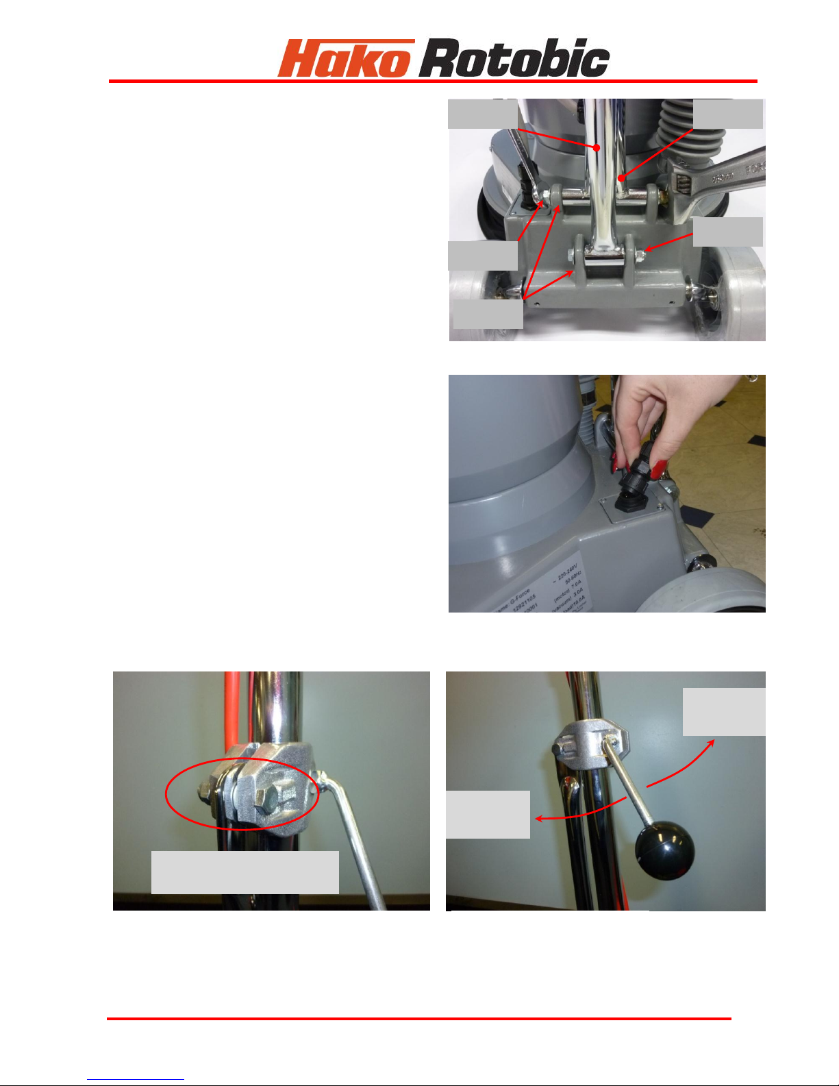
Ensure correct handle height adjustment for control.
Violent handle movement by operator will cause rapid sideways movement and may cause
operator to lose control.
Fit quality brushes and pads, correctly sized, to suit application.
Ensure floor is uniformly wetted when wet scrubbing, and that floor surface is uniform, to
minimize rapid sideways movement of the machine.
Ensure the rear wheels are UP when in use.
Ensure the machine is in constant motion over the floor area. Keeping the machine in a
localized spot may result in friction burns to the floor.
Trips, Slips and Falls
Do not wear open top footwear when using this equipment.
Wear slip resistant footwear at all times. Wear chemical resistant footwear when wet
scrubbing or stripping.floors.
Ensure electrical cord is clear of machine and operators feet.
Use appropriate signage and barriers e.g. ‘Cleaning in Progress’ to alert public to cleaning
activity.
Burns, Fire, or Explosion
Do not vacuum anything that is burning or smoking such as cigarettes, matches or hot ash.
Do not use machine in areas where flammable or combustible liquids, vapors or gases are
present.
Do not operate near explosive materials such as solvents, thinners, fuels or grain dust.
Muscloskeletal Injury
Change brushes and pads using correct posture.
Adjust handle to correct height and operate machine using correct posture.
Hold handle firmly at start, relax grip and maintain a straight wrist when machine is running.
Do not twist at the waist when slewing the machine or turning, turn using your feet.
Using mechanical aids or team lifting, when lifting the machine
Do not pull machine upstairs.
Do not heel the machine to the point where the machine is on its edge, this can cause injury,
damage to the handle, or damage to the floor.
Respiratory Damage/Illness due to Irritant Dust.
Do not use machine for vacuuming hazardous dust/particulates as defined in clause 50,
WorkCover NSW, Occupational Health and Safety Regulation 2001.
Filtration efficiency, vacuum airflow, particulate size and quantity must be considered in the
assessment of emissions.

7
SPECIFICATIONS
Main Motor
Type: Induction 4 Pole CSCR
Voltage and Frequency: 220 –240 Volts a.c. / 50 –60 Hz
Power Output: 1500 watts @ 8.3 amps
Vacuum Motor
Type: Single stage Flo-Thru
Voltage and Frequency: 220 –240 Volts a.c. / 50 –60 Hz
Air Flow: 25 litres/sec
Transmission
Type: HTD®double reduction timing belt.
Output speed: Standard 430 rpm / Hi-Torque 215 rpm at 50 Hz
Standard 515 rpm / Hi-Torque 257 rpm at 60 Hz
Noise
Noise: 68dBAwith Bassine brush on vinyl flooring.
Filter / Filtration
Media: Polyester 96.9% Efficiency EN 60312 Dust
Capacity: 2.5 Litre
Electrical Cord
Type / Length: 15 amp 3 core normal duty 15m long
Handle
Safety: Mechanical interlock
Activation: Lever activated double pole micro-switch
Stopping: Unattended automatic stop incorporated
Adjustment: Lever operated clamp, with infinitely variable
height adjustment through 90°
Wheels
Type / diameter: Retractable and non-marking / 150mm dia.
Weight (No Brush)
44 kg
Brush / Pads
Size: 45cm (across bristles) brush, or 45cm pad
holder suitable for 45cm pad.
Compliance
Standards: Australian and New Zealand Standards
AS/NZS 60335.1 & 60335.2.10
Electromagnetic
Conformity
Declaration: Australian and New Zealand Standard
AS/NZS CISPR 14.1
Marking: C-Tick Mark N3771

8
ELECTRICAL CIRCUIT DIAGRAM G-FORCE

9
G-FORCE Classic Chassis Assembly Parts List
ITEM
No.
PART
No.
DESCRIPTION
QTY
ITEM
No.
PART
No.
DESCRIPTION
QTY
1
13277001
Hose Inlet Assy G-Force
1
41
13220005
Cord Motor G-Force&FX Classic.
1
2
13270010
Hose Grey 32mm x 235+/-3 G-Force
1
42
13220009
Clamp 'P' Dia. 6.4 Mtg Hole 5.2 Zn Pl
2
3
13217000
Bracket EMI Filter Assy
1
43
13380040
Screw No.10 x 3/8 Pan Taptite ZP
3
4
13380041
Screw No. 10 x 1/2 S/T Pan ZP
3
44
13320001
Motor Vac 650W Single Stage Flo-Thru
1
5
13260002
Grommet 8.7x12.7x6.4 Panel
4
45
13280007
Insulation Strip Wall Canister
1
6
13220006
Cord Vacuum G-Force & FX Classic
1
46
13260010
Gasket Ring 150 OD x 12 Xsection
1
7
13280006
Insulation Vac Chamber Wall Chassis
1
47
13227706
Canister Polisher Assy
1
8
13280005
Insulation Disc Vac Chamber
1
48
13420020
Washer 1/4 x 1/2 x 18# Flat ZP
4
9
13227703
Connector Panel Lock Assy
1
49
13330011
Nut 1/4 UNC Hex Steel ZP
4
10
13380016
Screw No. 4 x 1/2 S/T Pan ZP
2
50
13250001
Filter Bag Polisher 167Dia x 125L PE
1
11
13350001
Plate Gland G-Force Classic
1
51
13310005
Lid Canister Red
1
12
13330013
Nut 3/8 Hex UNC Nyloc
1
52
13380044
Screw M5 x 8 Grub Oil Blackened
1
13
13420030
Washer 3/8 x 3/4 x 18# Flat ZP
2
53
13350024
Pulley 22t Motor Assy G-Force HT
1
14
13330012
Nut 5/16 UNC Hex Nyloc
1
53
13350025
Pulley 30t Motor Assy
1
15
13420025
Washer 5/16 x 3/4 x 18# Flat ZP
2
54
13210003
Belt 600-8m-21HP
2
16
13210012
Bolt 5/16 UNC x 3 Hex ZP
1
55
13350026
Pulley 24-59t Counter Assy G-Force HT
1
17
13210020
Bolt 3/8 UNC x 5 Hex ZP
1
55
13350027
Pulley 30-55t Counter Assy
1
18
13350012
Pin 1/4 x 1 Spring ZP
2
56
13380045
Screw M5 x 80 Socket Head Cap
1
19
13270006
Hose Pressure 6 I.D. X 14mm O.D.
0.03
57
13350030
Pulley 55t Brush Assy G-Force
1
20
13200001
Axle G-Force 12.7 O.D. CrP
1
57
13350031
Pulley 59t Brush Assy G-Force HT
1
21
13420037
Washer 1/2 x 1-1/8 x 16# Flat ZP
6
58
13380050
Screw M6 x 16 Socket Head Cap ZP
2
22
13420100
Wheels 150mm G-Force & Focus
2
59
13420035
Washer 12 x 4 x 2.5 RECT Sect Sprg
2
23
13420039
Washer 1/2 UC D6143 Starlock ZP
2
61
13350015
Plate Baffle G-Force
1
24
13220023
Cap Axle 1/2 CP
2
60
13380080
Screw M12 x 20 Set Hex ZP
2
25
13380017
Screw No. 4 x 5/8 S/T Pan ZP
2
62
13260006
Guard Pulley G-Force
1
26
13390006
Terminal Block 500-35DS 12 Way
0.33
63
13210005
Bumper G-Force
1
27
13220024
Cover Junction Box G-Force
1
64
13420021
Washer 1/4 x 7/8 x 18# Flat ZP
4
28
13380015
Screw No. 4 x 1/4 S/T Pan ZP
2
65
13380060
Screw 1/4W x 3/8 Set Hex ZP
4
29
13210010
Bolt 5/16W x 1 Hex ZP
4
66
13420046
Washer 16 x 28 Sprg Push On Fix ZP
1
30
13420027
Washer 5/16 x 5/64 x 5/64 SQ Sprg
4
67
13250010
Fabric Skirt G-Force
1
31
13420025
Washer 5/16 x 3/4 x 18# Flat ZP
4
68
13240001
Extrusion LDPE Skirt G-Force
1
32
13380062
Screw 1/4W x 3 M/T RDHD ZP
4
68
13240003
Extrusion LDPE Skirt G-Force Sander
1
33
13420022
Washer 1/4 x 1/16 x 1/16 SQ Sect Sprg
12
69
13220027
Chute Vac. & Insert Assy G-Force
1
34
13220021
Chassis G-Force Classic
1
70
13387000
Skirt Assy G-Force
1
35
13420051
Washer 22 x 70 x 1 Eccentric SS
1
70
13387002
Skirt Assy G-Force Sander
1
36
13420050
Washer 7/8 x 1-5/8 x 14# Flat ZP
1
71
13360000
Quick Release Adaptor Complete
1
37
13330016
Nut 1/2BSPP Hex ZP
1
72
13380071
Screw M8 x 35 CSK PH ZP
3
38
13220019
Cap 1/2 BSP Red Plastic
1
ACCESSORIES
39
13320000
Motor Polisher CMG 1500 W
1
73
13210060
Brush G45cm Bassine QR
1
13300001
Key Motor 3/16 x 3/16 x 1
1
13210061
Brush G45cm Soft Nylon QR
1
13220035
Cap Start 108-130µF 86 x 46
1
13210063
Brush G45cm Hard Nylon QR
1
13220036
Cap Run 30 µF 45 x 92 DQC
1
13210064
Brush G45cm Tynex QR
1
13220040
Cover Cap. Start
1
13350110
Pad Holder G45cm QR
1
13220041
Cover Cap. Run
1
13350102
Pad Holder G40cm Sandscreen QR
1
13380006
SwitchThermal Overload Manual
1
13350103
Pad Holder G40cm Sandpaper QR
1
13250015
Fan Plastic 22mm
1
13380150
Sandscreen 45cm x 60# Coarse
1
13420060
Washer Fan Pressed Steel
1
13380151
Sandscreen 45cm x 80# Medium
1
13220042
Cowl Plastic Motor Housing
1
13380152
Sandscreen 45cm x 100# Fine
1
13380007
Switch Centrifugal
1
13380153
Sandscreen 45xm x 120# Very Fine
1
13350016
Plate Switch
1
13380154
Sandscreen 45xm x 150# Very Fine
1
40
13210002
Bush Strain Relief
1

10
CHASSIS G-FORCE CLASSIC

11
G-FORCE Industrial & Commercial Handle
No.
Part Name
Part No.
Qty
No.
Part Name
Part No.
Qty
Handle G-Force IC Assy
13277050
21
Bolt 5/16W x 1-1/2 Hex ZP
13210011
1
1
Handle Grip
13270005
2
22
Grommet Loom Cord
13260001
1
2
Pin M6 x 20 Dowell CP
13350010
2
23
Cord Polisher 3 Core 15m x 15A
13220007
1
3
Housing Handle Lower G-Force IC
13270001
1
24
Lever Handle Clamp IC
13310003
1
5
Wire N Handle Focus/G-Force IC
13420002
1
26
Knob Handle 41Dia x 3/8 BSW
13300000
1
6
Wire A Handle Focus Suds/G-Force IC
13420001
1
27
Screw WN1412 K B 50 X 20 Z
13380048
6
7
Insulator Post Fit Utilux H2818
13280000
2
28
Housing Handle Lid IC
13270004
1
9
Screw No.10 x 3/8 Pan Taptite
13380040
1
29
Lever Safety Interlock Handle IC
13310002
1
10
Clamp Cord Handle IC
13220014
2
30
Lever Start/Run Handle IC
13310001
1
11
Screw WN1412 K B 40 X 16 Z
13380026
4
31
Screw No. 7 x 25 HiLo Pan ZP
13380025
2
12
Terminal Block ANE
13390005
1
32
Switch Micro 2HP Terminals 2 x Com, 2 x NO
13380002
1
13
Screw No. 6 x 5/8 S/T Pan ZP
13380020
2
33
Spring Compression Stainless Steel
13380010
1
14
Tube Handle IC
13390001
1
34
Nut M6 Hex Steel ZP
13330010
2
15
Washer 15.8 x 8.05 x 0.90 Belleville ZP
13420045
1
35
Housing Handle Cover IC
13270003
1
16
Nut 5/16 Hex UNC Nyloc
13330012
1
36
Screw M6 x 45 M/T Pan ZP
13380052
2
17
Clamp Handle IC Set
13220015
1
37
Label Handle IC
13310010
1
18
Tube Upright IC
13390000
1
38
Switch Rocker Red 15A SPST
13380000
1
19
Bush Strain Relief Utilux H2097B
13210001
1
39
Indicator Red 240V 0.3W T1200.04 & 152mm Leads
13280002
1
20
Cord Handle G-Force IC Assy
13227701
1
39
38

12
Hako Australia Pty Ltd Warranty Policy Effective July 1, 2008
Hako Australia Made Simple Limited Warrantly Policy
Hako Australia Pty Ltd warrants to the original purchaser/user that the product is free from defects in
workmanship and materials under normal use. Hako Australia Pty Ltd will, oblige under this warranty to
repair or replace at our factory or authorised dealer service outlet, parts that fail under normal use and
service when operated and maintained in accordance with the Parts Manual and Owners Guide, after
examination discloses it to have been defective. All warranty claims must be submitted through a Hako
Australia Pty Ltd Dealer or Authorised agent and approved by Hako Australia Pty Ltd.
This warranty does not apply to components replaced due to recommended service schedules, normal wear
and tear or to items whose life is dependent on their use and care.
Special warning to purchaser - Use of replacement parts not manufactured or supplied by Hako Australia
Pty Ltd will void all warranties expressed or implied. A potential health hazard exists without original
equipment replacement.
All warranted items become the sole property of Hako Australia Pty Ltd or its original manufacturer,
whichever the case may be.
Hako Australia Pty Ltd disclaims any implied warranty, including the warranty of merchantability and the
warranty of fitness for a particular purpose. Hako Australia Pty Ltd assumes no responsibility for any special,
incidental or consequential damages.
The limited warranty is applicable only to the original user/purchase or this product. Hako Australia Pty Ltd is
not responsible for costs or repairs performed by persons other than those specifically authorised by Hako
Australia Pty Ltd. This warranty does not apply to damage from transportation, alterations by unauthorised
persons, misuse or abuse of the equipment, use of non-compatible chemicals, or damage to property, or loss
of income due to malfunction of the product. If a difficulty develops with this machine, you should contact the
dealer from whom it was originally purchased.
Hako Australia Pty Ltd warranty period for Rotobic Focus Scrubber / Polisher for Parts and Labour is one (1)
year.
Hako Australia Pty Ltd or Authorized agents are required to submit all invoices when using or claiming for a
third party or subcontractor as part of their Warranty claim.
Hako Australia Pty Ltd is to approve or disapprove and clear for payment or credit within 30 days of receiving
a complete Warranty claim form from its Dealer or Authorised agent.
Hako Australia Pty Ltd is to advise by writing if a claim is disapproved or the total of the claim is varied from
that received.
Hako Australia Pty Ltd if claim is approved, will credit labour and parts to a Dealer or Authorised agent
account unless a Tax Invoice for payment accompanies the claim.
Dealer/Authorised agent is required to hold the replaced parts under warranty until approval or disapproval
has been received by Hako Australia Pty Ltd for a period of 90 days.
Dealer/Authorised agent is responsible for the freight or equipment and parts returned for warranty. These
are to be returned when and only if Hako Australia Pty Ltd specifically requests their return for inspection.
Ensure the name of Hako Australia Pty Ltd manager granting approval or requesting these returns is
included on the return goods.
Table of contents
Other Hako Robotic Scrubber manuals
Popular Scrubber manuals by other brands

NSS
NSS WRANGLER 1708CE Operation manual

Sandia
Sandia 80-4000-H Safety, operation and maintenance manual with parts list

Pts
Pts EUREKA E81 Operator's guide

Professional
Professional TWIST-N-BLITZ 9305 instruction manual

CDA
CDA EIN60 INSTALLATION, USE AND MAINTENANCE GUIDEBOOK

DIVAR
DIVAR AH-101CAT INSTALLATION & SPECIFICATIONS