ARQ1000A
ERROR
CORRECTION
TERMINAL
CONTENTS:
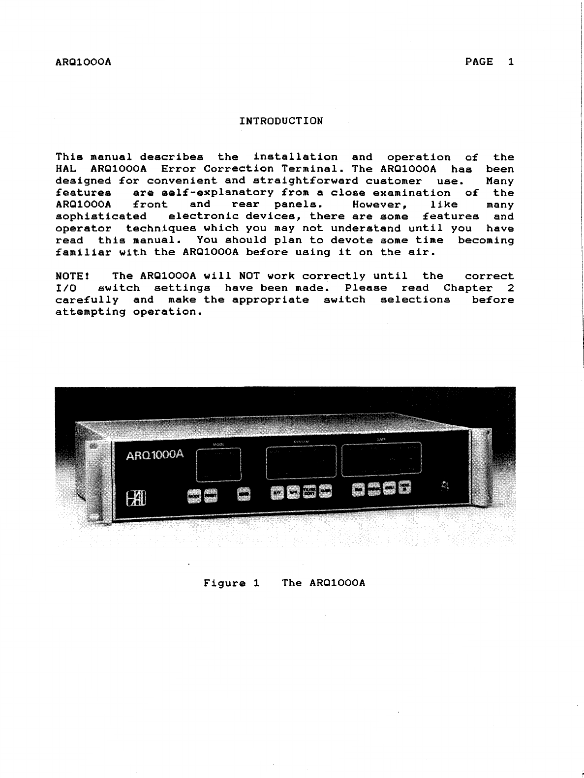
INTRODUCTION
. • • • • . . . . . . . . . . . . . . 1
CHAPTER
1.
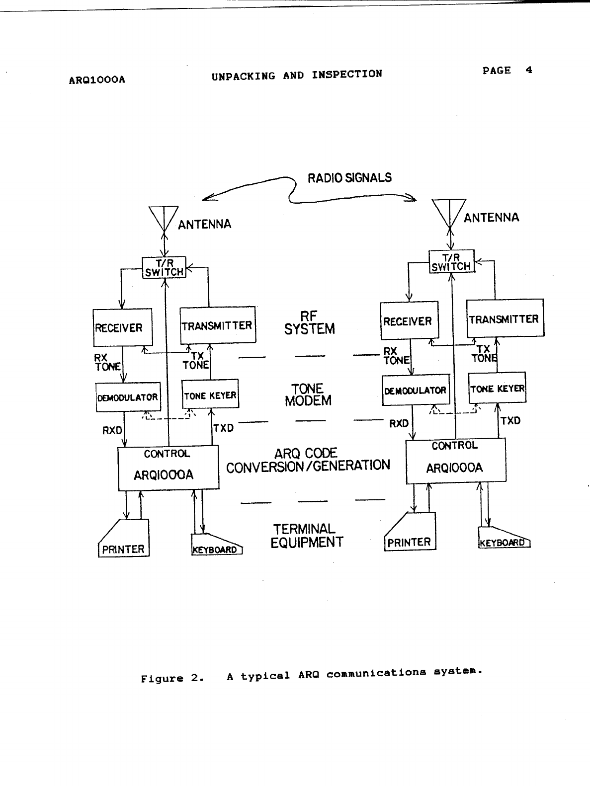
UNPACKING
AND
INSPECTION 2
CHAPTER
2.
INSTALLATION . • • • • • • • • • • • • • • • • • • 5
2.1
PRELIMINARY INSTALLATION CONSIDERATIONS • • • 5
2.1.1
MECHANICAL
REQUIREMENTS
• • • • . • • 5
2.1.2
ELECTRICAL
REQUIREMENTS
• • • • • • • 5
2.1.3
REAR
PANEL
CONNECTIONS
• • • • • • • • 6
2.2
TTY
TERMINAL
INTERFACE • • • . • • • • .
••
12
2.2.1
SELECTION
OF
TTY
TERMINAL
••••••
12
2.2.2
TERMINAL
CONNECTIONS
•••.•••••
15
2.2.3
CONNECTION
TO
HAL
DS3200
••.•..•
17
2.3
DEMODULATOR
CONNECTIONS
• • • • • • • . • • •
18
2.3.1
SWITCH
SELECTION
•••••••••••
18
2.3.2
CONNECTIONS
TO
HAL
DEMODULATORS
•••
19
2.4
TRANSMITTER
AND
RECEIVER CONSIDERATIONS • • •
21
CHAPTER
3.
OPERATING
THE
ARQ1000A • • • • • • . • • • •
•••
25
3.1
ARQ1000A
FRONT
PANEL
•••.••••••••
25
3.1.1
MODE
CONTROL
•••••••••••••
25
3.1.2
TRANSMISSION
CONTROL
SWITCHES
••••
26
3.1.3
SYSTEM
INDICATION
AND
CONTROL
••••
26
3.1.4
DATA
INDICATORS
••••••.••••
28
3.1.5
WRU
AND
HERE
IS
SWITCHES
.••••••
29
3.2
PROGRAMMABLE
FEATURES
OF
THE
ARQ1000A • • • •
30
3.2.1
ENTERING
PROGRAM
MODE
••••••••
30
3.2.2
PROGRAMMING
COMMANDS
AND
FORMAT
• • •
31
3.2.3
PROGRAMMING
THE
HERE
IS
MESSAGE
•.•
32
3.2.4
PROGRAMMING
THE
IDENTIFIER
CODES
• • •
32
3.2.5
CS
X/1
CONTROL
SIGNAL
PARAMETER
• • •
33
3.2.6
EC
ON/OFF
TERMINAL
ECHO
PARAMETER
.•
34
3.2.7
TIME
OUT
<TO>
PARAMETER
••••.••
35
3.2.8
WRU
CONTROL
COMMAND
• • . • • • • • •
35
3.2.9
DEFAULT
AFTER
RESET
PARAMETERS
• • • •
35
3.2.10
CONVERSATIONAL
FEC
<CF:>
••••.••
36
3.2.11
TRANSMIT
DELAY
<TO:>
.••.•••••
37
3.2.12
CONTROL
DELAY
<CD:>
•••••••••
38
3.2.13
AUDIO
DELAY
<AD:>
•.••••••••
39
3.2.14
BUFFER
CLEAR
<BC:>
•.•••••.•.
39
3.2.15
ST:
LIST
STATUS
COMMAND
••••..•
40
3.2.16
EX: EXIT
PROGRAMMING
COMMAND
•••••
40