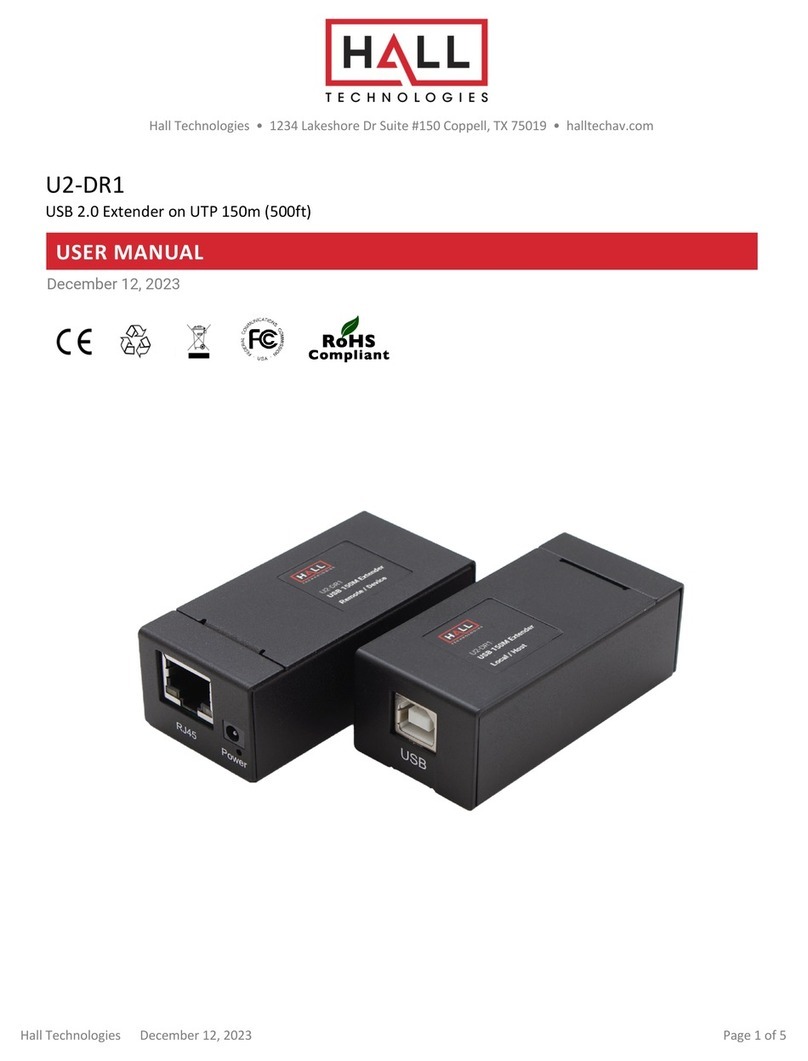
Hall Technologies HT-Gemini User manual

Hall Technologies November 4, 2022 Page 1 of 26
Hall Technologies • 1234 Lakeshore Dr Suite #150 Coppell, TX 75019 • halltechav.com
HT-Gemini
4K 6 Multiformat Input Extender Switch with USB Extension for Soft Codec
User Manual
Version: 1.0
HT-GEMINI-RX
HT-GEMINI-TX

Hall Technologies November 4, 2022 Page 2 of 26
Important Safety Instructions
!
1. Do not expose this apparatus to rain, moisture, dripping or
splashing and that no objects filled with liquids, such as
vases, shall be placed on the apparatus.
2. Do not install or place this unit in a bookcase, built-in
cabinet or in another confined space. Ensure the unit is well
ventilated.
3. To prevent risk of electric shock or fire hazard due to
overheating, do not obstruct the unit’s ventilation openings
with newspapers, tablecloths, curtains, and similar items.
4. Do not install near any heat sources such as radiators, heat
registers, stoves, or other apparatus (including amplifiers)
that produce heat.
5. Do not place sources of open flames, such as lighted
candles, on the unit.
6. Clean this apparatus only with dry cloth.
7. Unplug this apparatus during lightning storms or when
unused for long periods of time.
8. Protect the power cord from being walked on or pinched
particularly at plugs.
9. Only use attachments / accessories specified by the
manufacturer.
10. Refer all servicing to qualified service personnel.

Hall Technologies November 4, 2022 Page 3 of 26
Table of Contents
Introduction ........................................................................................................................................ 4
Overview .................................................................................................................................... 4
Features .................................................................................................................................... 4
Package Contents .............................................................................................................................. 5
Panel Description ............................................................................................................................... 6
Transmitter ............................................................................................................................... 6
Front Panel ............................................................................................................................. 6
Rear Panel .............................................................................................................................. 7
Receiver ..................................................................................................................................... 9
Front Panel ........................................................................................................................... 9
Rear Panel ......................................................................................................................... 10
Installation and Wiring .................................................................................................................... 11
Installation ............................................................................................................................. 11
Wiring ..................................................................................................................................... 11
Key Functions .................................................................................................................................. 13
Auto Switch ............................................................................................................................ 13
USB Control ............................................................................................................................ 14
RS232 Control ........................................................................................................................ 17
Web UI Control ................................................................................................................................. 17
Access the Web Interface ..................................................................................................... 17
Web Interface Introduction ................................................................................................... 18
Status ................................................................................................................................ 18
Config ................................................................................................................................ 18
Setting ............................................................................................................................... 18
Config Page ..................................................................................................................................... 19
Auto Switch ............................................................................................................................ 19
Input HDCP ............................................................................................................................ 19
EDID ........................................................................................................................................ 19
Display .................................................................................................................................... 20
Relay Controller ..................................................................................................................... 20
Setting Page .................................................................................................................................... 21
Generic Setting ...................................................................................................................... 21
Automatic Logout .................................................................................................................. 21
Network .................................................................................................................................. 21
Password ............................................................................................................................... 22
Firmware Upgrade ................................................................................................................. 22
System and Firmware ........................................................................................................... 22
Troubleshooting .............................................................................................................................. 23
Specifications .................................................................................................................................. 24
Transmitter ............................................................................................................................ 24
Receiver .................................................................................................................................. 25
Transmission Distance ......................................................................................................... 26
Hall Technologies November 4, 2022 Page 4 of 26
Introduction
OVERVIEW
This product is a 4K 6 Multi-format Inputs Extender Switch with USB Extension for a soft codec,
which provides AV switching, USB, HDMI, DP, VGA, and USB-C extension, plus system control for
meeting spaces using PC-based conferencing codecs such as Microsoft Skype, Webex by Cisco
and Citrix GoTo Meeting. The kit offers six video inputs shared between both devices for HDMI,
Display Port, VGA plus analog audio in and USB-C video signals. To simplify conference room
device management, the kit provides four USB Type-B connectors for host computers. Six built-
in USB hubs, three on the transmitter and three on the receiver, allow for numerous Human
Interface Devices (HID) as well as USB cameras and microphones.
The kit is compatible with Ultra High-Definition source up to 4K/UHD@60 Hz with 4:2:0 color
subsampling. All audio, video, data, control, USB, and Ethernet transmission between the two
devices is carried over a single, Ethernet-enabled HDBaseT link up to 100m/330ft.
It simplifies classroom and small office system integration, for installation beneath conference
tables and in lecterns, to provide localized presentation switching support.
FEATURES
! HDMI 2.0 with 4k@60Hz (Chroma sub-sampling 4:2:0 8-bit only) and HDCP 2.2
compliance, VGA input up to 1920x1200@60Hz.
! Provides a variety of interfaces including USB-C to simplify meeting room devices
management.
! Inputs connected to either the transmitter or the receiver can be displayed on the HDMI out
on either the transmitter or the receiver or both simultaneously.
! Automatically detects active inputs when sources are connected.
! Supports USB hosts such as Desktop and Laptop, and peripheral USB devices such as
keyboard, mouse, microphone, speaker, camera, and whiteboard for a conference system.
! Ethernet can be connected into either the receiver or the transmitter, providing LAN
accessibility for users.
! Allows connected displays to be controlled via CEC commands or front panel buttons.
! Relay commands can be triggered to control relay devices such as projection screens.
! RS232 pass through; IR pass through from TX to RX.
! API Control via LAN interface and RS232-C.
! De-embedded audio can be routed out of the Receiver to an external amplifier.

Hall Technologies November 4, 2022 Page 5 of 26
Package Contents
TRANSMITTER:
! 1 x Transmitter
! 1 x DC 12V Power Adapter with US Pins
! 1 x DC 12V Power Adapter with UK Pins
! 1 x DC 12V Power Adapter with EU Pins
! 1 x DC 12V Power Adapter with AU Pins
! 2 x Phoenix Male Connector
(3.5 mm, 3 pins)
! 1 x IR Receiver Cable
! 2 x Mounting Brackets (with Screws)
RECEIVER:
! 1 x Receiver
! 1 x DC 12V Power Adapter with US Pins
! 1 x DC 12V Power Adapter with UK Pins
! 1 x DC 12V Power Adapter with EU Pins
! 1 x DC 12V Power Adapter with AU Pins
! 5 x Phoenix Male Connector
(3.5 mm, 3 pins)
! 1 x IR Emitter Cable
! 2 x Mounting Brackets (with Screws)

Hall Technologies November 4, 2022 Page 6 of 26
Panel Description
TRANSMITTER:
FRONT PANEL
No.
Name
Description
1
POWER LED
Lights on when the device is powered on.
2
VGA IN Selection Button
and LED
VGA IN selection button: press the button to select the VGA source as the
input.
LED: The LED is located directly above the button.
• LED On: VGA source is selected as the input.
•
LED
Off: VGA source is not selected.
3
DP IN Selection Button
and LED
DP IN selection button: press the button to select the DisplayPort source as
the input.
LED: The LED is located directly above the button.
• LED On: DP source is selected as the input.
•
LED
Off: DP source is not selected.
4
TX HDMI IN Selection
Button and LED
TX HDMI IN selection button: press the button to select the HDMI source on
the transmitter side as the input.
LED: The LED is located directly above the button.
• LED On: HDMI source on the TX is selected as the input.
•
LED
Off: HDMI source on the
TX is not selected.
5
USB-C IN Selection
Button and LED
USB-C IN selection button: press the button to select
the
USB-C source as
the input.
LED: The LED is located directly above the button.
• LED On: USB-C source is selected as the input.
•
LED
Off: USB-C source is not selected.
6
RX HDMI IN 1 Selection
Button and LED
RX HDMI 1 selection button: press the button to select the HDMI source on
the receiver side as the input.
LED: The LED is located directly above the button.
1 2 3 4 5 678 9 10 11

Hall Technologies November 4, 2022 Page 7 of 26
No.
Name
Description
• LED On: HDMI 1 source on the RX is selected as the input.
•
LED
Off: HDMI 1 source on
the
RX is not selected.
7
RX HDMI IN 2 Selection
Button and LED
RX HDMI 2 selection button: press the button to select the HDMI source on
the receiver side as the input.
LED: The LED is located directly above the button.
• LED On: HDMI 2 source on the RX is selected as the input.
•
LED
Off: HDMI 2 source on
the
RX is not selected.
8
Display Control Button
and LED
Display control button:
• Single press button—turn all displays on;
• Hold button for 3s—turn all displays off.
LED: The LED is located directly above the button and lights up when the
button is pressed
.
9
Screen ▲ Button and
LED
Screen ▲ Button: press to
raise a projection screen or open window
shades.
LED: The LED is located directly above the button and lights up when the
button is pressed.
10
Screen ▼ Button and
LED
Screen ▼ Button: press to
lower a projection screen or close window
shades.
LED: The LED is located directly above the button and lights up when the
button
is pressed
.
11
Update
Connection for updating firmware with the update software tool. (Reserved)
REAR PANEL
No.
Name
Description
1
VGA IN
Connect to a VGA source.
2
AUDIO IN
Connect to an audio source. Audio follows the VGA input source.
3
DP IN
Connect to a DisplayPort source.
1 2 34 5 678
910 11 12 13 14 15 16

Hall Technologies November 4, 2022 Page 8 of 26
No.
Name
Description
4
TX HDMI IN
Connect to an HDMI source.,
5
USB-C IN
USB Type-C port (USB 3.1 Gen1, 5Gbps, support DisplayPort Alternate
Mode)
The following cables are recommended:
• USB Type-C to Type-C cable (USB 3.1 Gen 1 or above).
Connect to a USB-C source
.
6
HDMI OUT
Connect to an HDMI display.
7
HDBT OUT
Connect to the HDBT IN port of the receiver.
8
DC 12V IN
Connect to the DC 12V power adapter.
9
USB DEVICE
Connect to USB peripheral devices.
10
RS232-P
Connect to a
n
RS232 controller or RS232 controllable device for RS232 pass
through.
11
USB HOST 1
Connect to
the
PC
.
This USB follows
VGA IN and DP IN ports
when either of
thosesources are selected, and the USB devices (on TX and RX) can be
connected to the host PC.
12
USB HOST 2
Connect to a PC
.
This USB follows
HDMI IN port when the source is
selected, and the USB devices (on TX and RX) can be connected to the host
PC.
13
RS232-C
Connect to a
n
RS232 enabled device for API controlling.
Note:
This
is disabled
on TX
to control a projector
.
.
14
IR IN
Connect to the IR Receiver cable for passing through the remote signal to
RX.
15
LAN 1
Connect to an Ethernet device.
16
LAN 2
Connect to an Ethernet device.

Hall Technologies November 4, 2022 Page 9 of 26
RECEIVER:
FRONT PANEL
No.
Name
Description
1
POWER LED
Lights on if the device is powered on.
2
HDBT Button and LED
HDBT signal selection button: press the button to select the HDBT signal as
the input.
LED: The LED is located directly above the button.
• LED On: HDBT source is selected as the input.
•
LED
Off: HDBT source is not selected.
3
RX HDMI IN 1 Selection
Button and LED
RX HDMI IN 1 selection button: press the button to select the HDMI source
on the receiver side as the input.
LED: The LED is located directly above the button.
• LED On: Select HDMI 1 source on the RX is selected as the input.
•
LED
Off: HDMI 1 source on RX is not selected.
4
RX HDMI IN 2 Selection
Button and LED
RX HDMI IN 2 selection button: press the button to select the HDMI source
on the receiver side as the input.
LED: The LED is located directly above the button.
• LED On: HDMI 2 source on the RX is selected as the input.
•
LED
Off: HDMI 2 source on RX is not selected.
5
Display Control Button
and LED
Display control button:
• Single press button—turn all displays on;
• Hold button for 3s—turn all displays off.
LED: The LED is located directly above the button and lights up when the
button is pressed
.
6
Screen ▲ Button and
LED(Blue)
Screen ▲ Button: press to
raise a projection screen or open window
shades.
LED: The LED is located directly above the button and lights up when the
button is pressed.
7
Screen ▼ Button and
LED(Blue)
Screen ▼ Button: press to
lower a projection screen or close window
shades.
LED: The LED is located directly above the button and lights up when the
button
is pressed
.
8
Update Port
Connection for updating firmware with the update software tool. (Reserved)
1 2 3 4 5 6 7 8

Hall Technologies November 4, 2022 Page 10 of 26
REAR PANEL
No.
Name
Description
1
HDBT IN
Connect to the HDBT OUT port of the transmitter.
2
RX HDMI IN 1
Connect to an HDMI source.
3
RX HDMI IN 2
Connect to an HDMI source.
4
HDMI OUT
Connect to an HDMI display.
5
IR OUT
Connect to the provided IR emitter cable for emitting remote signal from TX.
6
AUDIO OUT
Connect to an audio system with the phoenix connector.
7
DC 12V
Connect to the DC 12V power adapter.
8
USB DEVICE
Connect to USB peripheral devices.
9
USB HOST 1
Connect to
the
PC
.
This USB follows
VGA IN and DP IN ports
when either of
thosesources are selected, and the USB devices (on TX and RX) can be
connected to the host PC.
10
USB HOST 2
Connect to a PC
.
This USB follows
HDMI IN port when the source is
selected, and the USB devices (on TX and RX) can be connected to the host
PC.
11
RS232-C
Connect to a projector for API controlling.
12
RS232-P
Connect to a
n
RS232 controller or RS232 controllable device for RS232 pass
through.
13
Screen△
Screen ▲ Button: press to
raise a projection screen or open window
shades.
LED: The LED is located directly above the button and lights up when the
button is pressed.
14
Screen▽
Screen ▼ Button: press to
lower a projection screen or close window
shades.
LED: The LED is located directly above the button and lights up when the
button
is pressed
.
15
LAN 1
Connect to an Ethernet device.
16
LAN 2
Connect to an Ethernet device.
1 2 34
1
56 7
8 9 10 11 12 13
1
14 15 16

Hall Technologies November 4, 2022 Page 11 of 26
Installation and Wiring
INSTALLATION
Note: Before installation, please ensure the devices are disconnected from the power source.
Steps to installing the device:
1. Attach the included installation bracket to
the enclosure using the screws provided.
The bracket height can be adjusted up or
down, or the bracket can face up or down
depending on the location.
2. Repeat the step for the other side of the
device.
3. Attach the brackets to the desired install
surface (installation hardware not included).
4. Repeat steps 1~3 to install the receiver.
WIRING
1. Connect the HDMI/VGA/DP/USB-C sources to the HDMI IN/VGA IN/DP IN/USB-C IN ports
of TX or RX.
Note: The soft codec provides users the ability to connect a BYOD wireless system to the
HDMI IN as a source.
2. Properly connect displays or projectors to the HDMI OUT ports of the TX and RX, ensuring
both source and displays are compatible.
3. Connect a well-terminated Cat 5e/6/6a/7 cable with an RJ45 connector wired to 568B
standard at both ends from the HDBT OUT ports of the TX to the HDBT IN ports of the RX.
Note: For more information about the cable, please refer to the “Specifications” section.
4. Connect a PC to USB HOST ports with USB cables.
5. Connect USB peripheral devices to the USB DEVICE ports of the TX and the RX.
Combining above 4 and 5 steps: the PC and all USB peripheral devices connected to the TX
and the RX can be connected to the host PC
Note: For more information, please refer to “USB Control” section.
6. Connect an audio system such as an amplifier to the AUDIO OUT phoenix connector on the
RX.
7. Plug the IR emitter into the IR OUT port of the RX and plug the IR broadband receiver into the
IR IN port of the TX. With this, users can control the projector with its remote.
8. Connect one of the LAN ports to an Ethernet device such as an Ethernet switch.

Hall Technologies November 4, 2022 Page 12 of 26
Note: Only one LAN port is needed on the Ethernet switch, on either the TX or the RX.
9. Connect the power adapters to the TX and the RX.
10. Power on all attached devices.

Hall Technologies November 4, 2022 Page 13 of 26
Key Functions
AUTO SWITCH
Auto Switch can be enabled or disabled using either the Web UI or by sending the API command
to the device. (For more information, please refer to “Web UI Control” section and the separate
document “API Command Set for HT-GEMINI”)
WHEN THE AUTO SWITCH IS ON (DEFAULT):
! When the HT-GEMINI powers up, if the source selected before HT-GEMINI being powered
off is still active, the HT-GEMINI will automatically switch to this source. If the previously
selected source is not active and there is more than one input source connected, the HT-
GEMINI will output signal following the auto switch priority order: VGA > DP > TX HDMI IN >
USB-C > RX HDMI1> RX HDMI2.
! When a new input source is connected, the HT-GEMINI will automatically switch over to this
source.
! When the currently selected source is disconnected, the HT-GEMINI will switch to the next
active input source with highest priority, and if there is no other active input source the HT-
GEMINI will keep the currently selected source.
WHEN THE AUTO SWITCH IS OFF:
• When a new source is connected, the HT-GEMINI will not automatically switch to that source.
Users will need to switch to the desired source manually by pressing the appropriate input
button on either the TX or the RX.

Hall Technologies November 4, 2022 Page 14 of 26
USB CONTROL
Prior to operation make sure the PC and all other peripheral USB devices are connected.
! Connect a PC to the USB HOST ports with USB cables.
! Connect peripheral USB devices to the USB DEVICE ports of the TX and the RX.
The white outline on the back panel of the transmitter and receiver represents one group.
When the input source in the same group is selected, the peripheral USB devices (on both the
TX and the RX) can be connected to the host PC. Please refer to the following diagrams.
Note: The USB-C input already has a built-in recognizable function, which means that when you
select the USB-C input, the PC can be connected to another peripheral USB device directly.
1. VGA / DP source input on the TX is selected:
In this connection method, the VGA IN, AUDIO IN and TX USB HOST 1 are in a group. When the
VGA input is selected, the peripheral USB devices (on both the TX and the RX) can be connected
to the PC which is connected to the USB HOST 1.

Hall Technologies November 4, 2022 Page 15 of 26
2. TX HDMI IN source on TX is selected:
In this connection method, the TX HDMI IN and TX USB HOST 2 are in a group. When the TX
HDMI IN is selected, the peripheral USB devices (on both the TX and the RX) can be connected
to the PC which is connected to USB HOST 2.
3. USB-C source on TX is selected:
In this connection method, when the USB-C input is selected, the peripheral USB devices (on
both the TX and the RX) can be connected to the PC, which connected to USB-C port directly.

Hall Technologies November 4, 2022 Page 16 of 26
4. RX HDMI IN 1 on RX is selected:
In this connection method, the RX HDMI IN 1 and RX USB HOST 1 are in a group. When the RX
HDMI IN1 is selected, the peripheral USB devices (on both the TX and the RX) can be
connected to the PC connected to RX USB HOST 1.
5. RX HDMI IN 2 on RX is selected:

Hall Technologies November 4, 2022 Page 17 of 26
In this connection method, the RX HDMI IN 2 and RX USB HOST 2 are in a group. When the RX
HDMI IN 2 is selected, the peripheral USB devices can be connected to the PC which is
connected to RX USB HOST 2.
RS232 CONTROL
Advanced users may choose to control the HT-GEMINI through the RS232 control port. A UART
cable is needed to connect a PC or control system. The API command for RS232 control is
available in the separate document “API Command Set HT-GEMINI”. To properly execute API
commands connected with RS232, please ensure the RS232 interface and the control PC are
configured correctly.
Parameters
Value
Baud Rate
115200 bps
Data Bits
8 bit
Parity
None
Stop Bits
1 bit
Flow Control
None
Web GUI
The Web UI designed for this switcher allows for basic controls and device settings. This Web
UI can be accessed through a modern browser, e.g. Chrome, Safari, Firefox, IE10+, etc.
To get access the Web UI:
1. Connect the LAN port of the switcher to a local area network. The HT-GEMINI by default is
set to DHCP. Ensure there’s a DHCP server in the network so that the device can obtain a
valid IP address. (If there is no DHCP server the switcher will revert to a 169.254.x.x
address. An “arp -a” command in the command window can help locate the device.)
2. Connect the PC to the same network as the switcher.
3. Input the switcher’s IP address in the browser and press Enter, the following window pops
up. (See OSD section to easily view the IP address)

Hall Technologies November 4, 2022 Page 18 of 26
4. Input the password (default password: admin) and click Login to enter the main page.
The Web UI main page includes Status, Config, and Settings Tabs.
• Status – offers manual input selections as well as turning the display on/off and
raising/lowering the projection screen.
• Config – offers settings of Auto Switch, HDCP, EDID, Display controls, and Relay Control.
• Setting – offers settings for Key Lock, Automatic Logout, Network settings, Password
changes, Firmware Upgrade, and Factory reset.

Hall Technologies November 4, 2022 Page 19 of 26
Config Page
AUTO SWITCH
UI Element
Description
Auto Switch
Auto Switch enabled “ON” or disabled “OFF”. (See Auto Switch section above for
more information.)
INPUT HDCP
UI Element
Description
Input HDCP
HDCP can be enabled/disabled on each of the inputs.
• ON: The input port supports HDCP
• OFF: The input port does not support HDCP
EDID
UI Element
Description
EDID
EDID settings can be applied to each of the inputs. Click “Apply” to save the
selected EDID setting.

Hall Technologies November 4, 2022 Page 20 of 26
DISPLAY
UI Element
Description
Auto Display Control
Used to enable “ON” or disable “OFF” display control when HT-GEMINI detects no
input sources.
Delay Time (min)
Set the desired delay time between 1 and 30 minutes before the HT-GEMINI
turns off a display when there is no signal input.
UART Baud Rate
Select the display’s baud rate setting from the drop down. Available baud rates are
9600, 19200, 38400, 57600, and 115200.
Hex or Text
Select whether the power on/off commands are in hexadecimal format or
character format.
End Flag
Select the end flag of the power on/off command. Options are NONE, \r, \n, or \r\n.
Power On Code
Enter the display’s power on and power off commands. Click to save the command
to the HT-GEMINI.
Power Off Code
RELAY CONTROLLER
UI Element
Description
Relay Mode
Select between Latch and Momentary for the relay mode.
• Latch: Level triggered.
• Momentary: Pulse triggered. Note, when momentary is selected, users can set
the delay time between triggers between 1 and 10 seconds.
This manual suits for next models
2
Table of contents
Other Hall Technologies Extender manuals

Hall Technologies
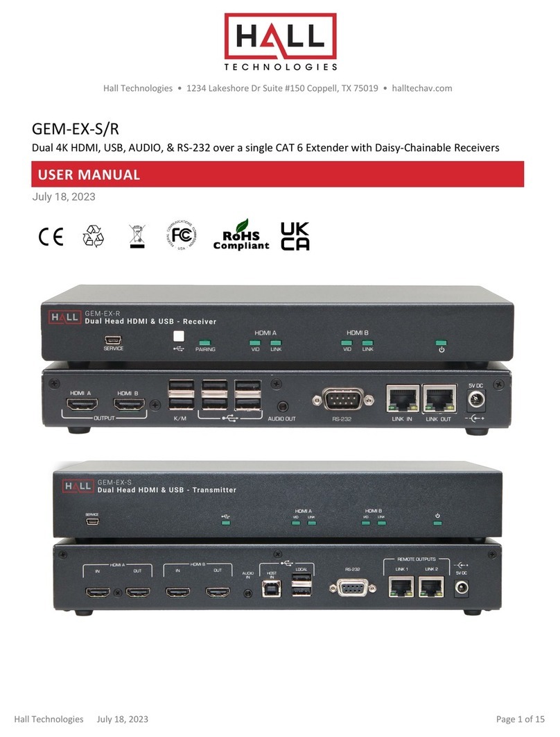
Hall Technologies GEM-EX-S User manual

Hall Technologies
Hall Technologies UH18 User manual

Hall Technologies
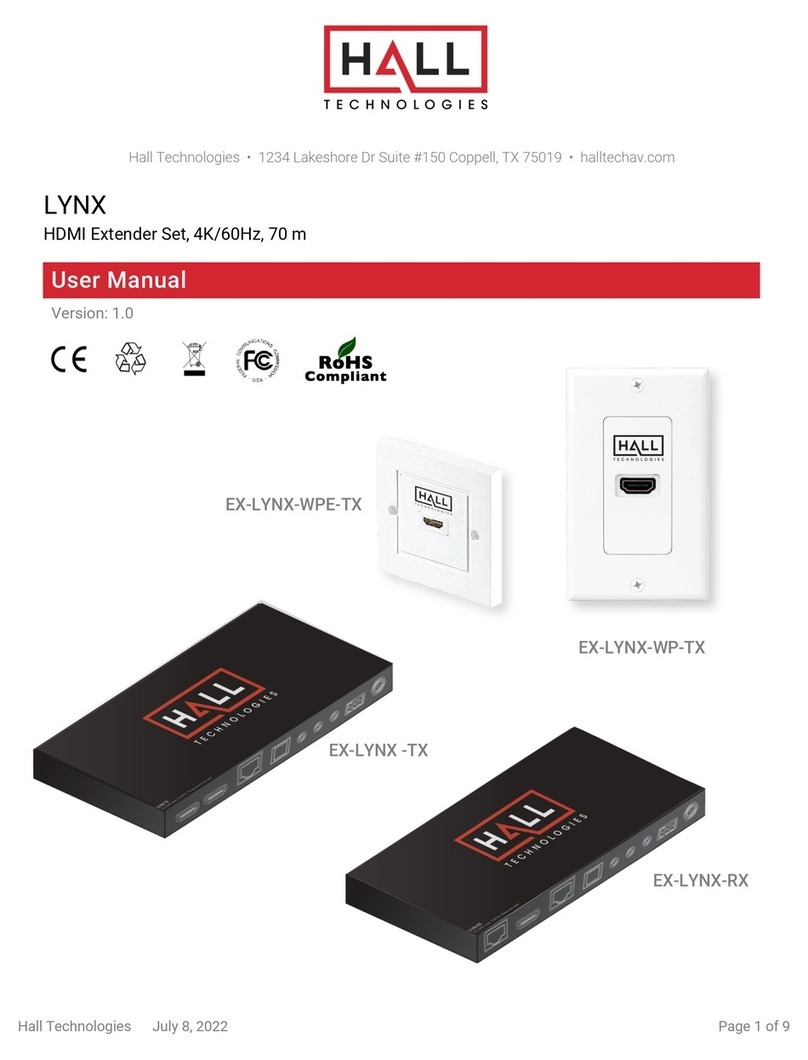
Hall Technologies LYNX Series User manual

Hall Technologies
Hall Technologies HT-AIM-70 User manual

Hall Technologies
Hall Technologies U2-DR1 User manual

Hall Technologies
Hall Technologies HT-AIM-100 User manual

Hall Technologies
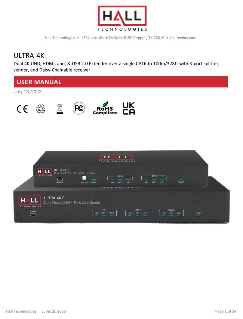
Hall Technologies ULTRA-4K User manual

Hall Technologies
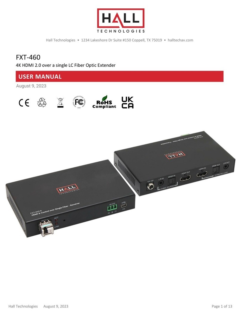
Hall Technologies FXT-460 User manual

Hall Technologies
Hall Technologies LYNX Series User manual

Hall Technologies
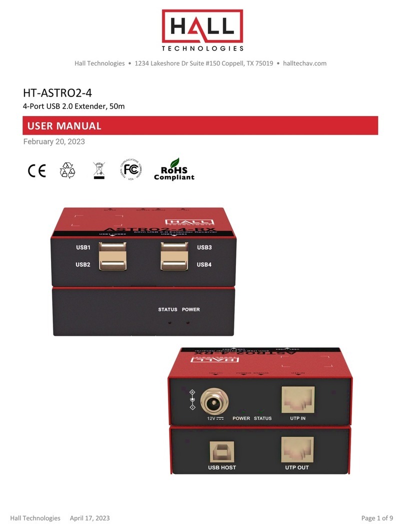
Hall Technologies HT-ASTRO2-4 User manual