manuals.online logo
Brands
  1. Home
  2. •
  3. Brands
  4. •
  5. MuxLab
  6. •
  7. Extender
  8. •
  9. MuxLab VGA Balun II User manual

MuxLab VGA Balun II User manual

© MuxLab Inc. 2007-2013
Specifications
Environment VGA. VESA VP&D 1.0, VIP ver 2.0.
Devices CRT/LCD monitors, plasma, laptops, PCs, projectors.
Transmission Transparent to the user.
Bandwidth DC to 60MHz
Input Signals Video: 1.1Vp-p
H &V sync: TTL standard. 300kHz max. bandwidth
Insertion Loss Less than 3 dB per pair over the frequency range.
Common Mode Rejection
(CMMR)
15kHz -60dB typ.
100kHz to 10MHz -40dB typ.
200MHz -20dB typ.
Return Loss -15dB max from DC to 60MHz
Connectors 500040/500042: DB15 HD Plug, RJ45 Shielded
500041/500043: DB15 HD Receptacle, RJ45 Shielded
Max. Distance via Cat 5
Twisted Pair
VGA: 640x480 pixels (15MHz) 450ft (137m)
SVGA: 800x600 pixels (30MHz) 350ft (107m)
XGA: 1024x768 pixels (60MHz) 250ft (76m)
SXGA: 1280x1024 pixels (100MHz) 200ft (61m)
WXGA:1366x768 pixels 180ft (55m)
RJ45 Pin Configuration
EIA 568 A or B
Reverse Polarity Sensitive
Pin 1 (R) Pin 2 (T) Balanced - Red
Pin 4 (R) Pin 5 (T) Balanced – Green
Pin 7 (R) Pin 8 (T) Unbalanced – Blue (7 sig, 8 gnd)
Pin 3 (R) Pin 6 (T) Unbalanced – H & V Sync
Compatibility Not compatible with the VGA Balun (500010, 500011, 500014) or
Active VGA Balun Kit (500035. 500036)
Reset button May be needed when used with certain display devices.
Grounding screw Grounding screw for optional use.
Cable Cat 5 or better unshielded twisted pair (UTP)
Impedance Input: RGB 75 ohms Output: RGB 100 ohms
Temperature Operating: 0° to 55° C. Storage:-20° to 85° C. Humidity: up to 95% non-
cond.
Enclosure ABS fire retardant plastic
Dimensions 2.40” x 2.25 x 1.00” (6.1 x 5.7 x 2.54 cm) plus 6: (15.2cm( lead on
500040 and 500042.
Weight 500041/500043: 2.34 oz (66 gms). 500040/500042: 3.87 oz (110 gms)
Mounting Free-standing. Separate Velcro mounting pad included
Warranty Lifetime
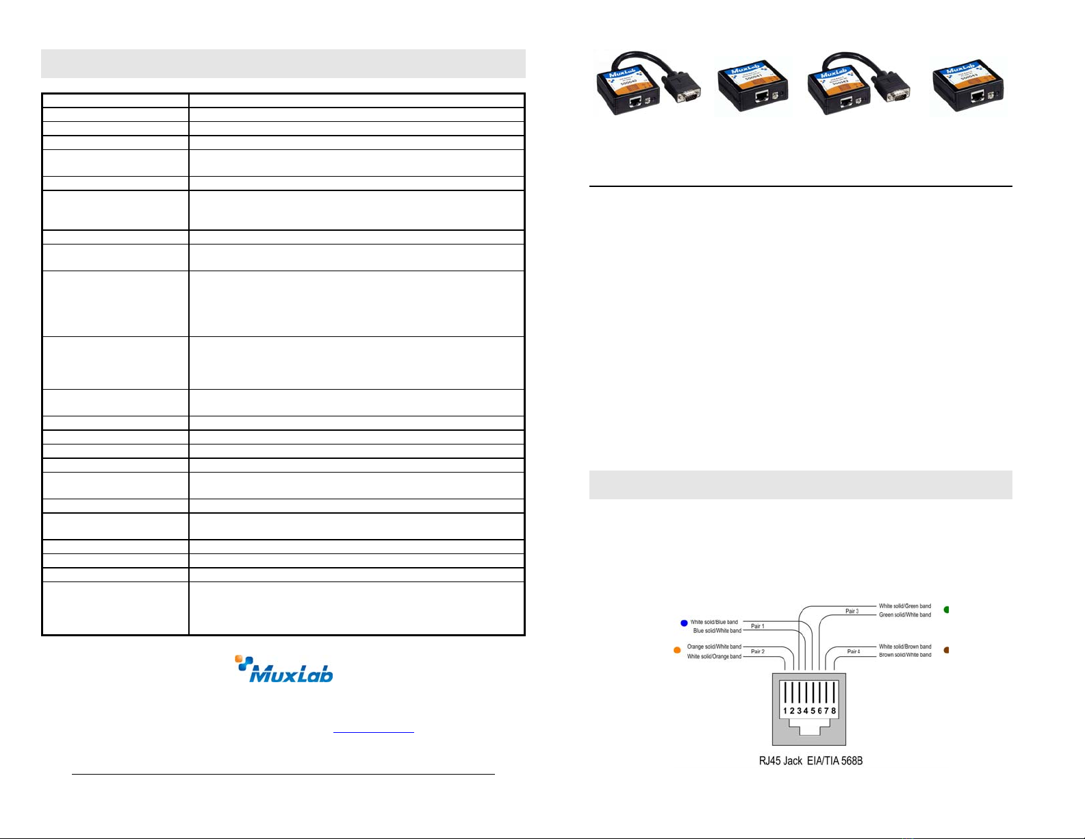
Order Information 500040 VGA Balun II, HD15 Plug, PC Side
500041 VGA Balun II, HD15 Receptacle, Monitor Side
500042 VGA Balun II, HD15 Plug, Monitor Side
500043 VGA Balun II, HD15 Receptacle, PC Side
8495 Dalton Road, Mount Royal, Quebec, H4T 1V5
Tel.: (514) 905-0588 Fax: (514) 905-0589
Toll Free (North America): (877) 689-5228
E-mail: videoease@muxlab.com URL: www.muxlab.com
94-000606-B SE-000579-B
VGA Balun II (500040, 500041, 500042, 500043)
Quick Installation Guide
Overview
The VGA Balun II eliminates costly and bulky VGA cable, allowing a VGA source
to be connected to a VGA monitor via one 4-pair Cat 5 unshielded twisted pair
(UTP) cable. Used in pairs, the VGA Balun II allows VGA video to be transmitted
up to 350ft (107m) via Cat 5 at 800 x 600 resolution. Each VGA connection
requires a VGA Balun II at the source (500040, 500043) and a VGA Balun II
(500041 or 500042) at the display.
Notes:
•The VGA Balun II does not support VGA handshaking and control signals.
Therefore it is necessary to set the monitor attributes prior to installing the
VGA Baluns. In order to do this, first connect the standard VGA cable directly
from the PC to the monitor and then set the monitor attributes to the required
settings (i.e.; resolution, color, etc). Also, in order to achieve optimum results
via twisted pair, set the Contrast and Brightness levels to maximum.
•The shield on the RJ45 connector is provided as an option for use in harsh
electrical environments where shielded twisted pair cable (STP) may provide
additional noise immunity. When using STP, ensure that the shield on both
sides is grounded.
Installation
1. Connect the 500040 or 500043 to the VGA output of the PC or VGA
distribution amplifier. Tighten the mounting screws on each balun.
2. Connect a Cat5 4-pair cable from the modular RJ45 jack of the 500040 or
500043 to the twisted pair cabling of the building. Wiring must be straight-
through and according to EIA 568A or 568B as shown in the following
diagram.
© MuxLab Inc. 2007-2013
3. Connect a 500041 or 500042 to the VGA input of the display.
4. Connect a Cat5 4-pair cable from the RJ45 connector of the 500041/500042 to
the twisted pair cabling of the building.
5. Power on the PC and VGA monitor.
6. Set monitor Contrast and Brightness to the desired levels. See typical application
below.
7. Set the monitor refresh rate to 60 Hz.
8. Due to the fact that some displays are more sensitive than others and may not sync
up correctly, a RESET button is provided on each VGA Balun II to allow these
displays to re-synchronize. A RESET button is on both the transmit and receive
side baluns for greater convenience and ease of access. If the initial setup yields an
improperly positioned image on the screen, using a pen or small screw driver, press
the RESET button located next to RJ45 jack on one of the baluns and then
immediately press the AUTOSET button located on the display unit. During this
time the image will change hue and gradually return to normal after approximately
fifteen (15) seconds. Please see following diagram.
Note: Some displays do not require the AUTOSET button to be pressed.
9. Set monitor Contrast and Brightness to the desired levels.
Note: In order to avoid accidentally resetting the connection, the Screensaver
options under Windows Display Settings must be set as follows:
a. Choose any screensaver except “NONE”
b. The “Turn Off Monitor “setting must be set to “NEVER”.
10. The VGA Balun features an optional grounding screw (see diagram above) that may
be used to clear up any image anomalies. For example, under some conditions,
there may be a slight difference in hue between the left hand side of screen and the
right. Connecting the ground terminal to earth ground will help clear this up.
However, if there is a ground loop problem in the building, connecting the ground
terminal may negatively affect the image. Therefore the ground screw should only
be used if it improves the overall image quality.
11. Note: During start-up, there may be a two (2) to three (3) second delay before an
image appears and the initial image may have a yellow hue. This is a normal
function of the product and is required in order to allow the monitor to sync up
correctly.
Troubleshooting
The following tables describe some of the symptoms, probable causes and possible
solutions in respect to the installation of the VGA Balun II. If you still cannot
diagnose the problem, please call MuxLab Customer Technical Support at 877-689-
5228 (toll-free in North America) or (+1) 514-905-0588 (International).
Symptom Probable Causes Possible Solutions
No video No continuity in video link Verify cable continuity between baluns.
No video Power off Check power supplies of VGA equipment.
No video PC settings Perform diagnostics on your VGA equipment
by following the manufacturer’s instructions.
Image distorted or
skewed.
Specific display unable to sync
up.
Follow RESET procedure in manual to force
display to sync up correctly.
Image not stable Defective link or equipment Verify VGA equipment interface integrity.
Unusual colors Reversed polarity Ensure wiring is straight-through polarity.
Background pattern EMI interference Identify possible radiating frequency sources
Try to isolate them from the video. Use
shielded twisted pair grounded at both ends.
Smearing Exceeded distance Verify cable grade. Use higher grade cable.
Weak contrast Exceeded distance Verify cable grade. Use higher grade cable if
necessary. Adjust contrast on monitor.
Weak contrast Unusual link attenuation Verify cable distance using cable tester.
Horizontal bars moving
upward in background
Ground loop problem Assure that PC and Monitor are connected to
the same ground. Disconnect PC or monitor
from the ground
1~2 pixel object random
dislocation
High noise level in the room.
Distance exceeded.
Set another resolution and refresh rate.
Review connectivity.
Slight variance in hue
between left and right
display margins
Slight background noise Connect ground terminal to earth ground.
Shaking image Possible ground loop problem Disconnect gnd terminal from earth ground.
Image has yellowish tint Marginal cabling Check Cat5 cable. Try different cable or re-
crimp RJ45 plugs.

This manual suits for next models

4

Other MuxLab Extender manuals

MuxLab 500402 User manual

MuxLab

MuxLab 500402 User manual

MuxLab 500464-V2 User manual

MuxLab

MuxLab 500464-V2 User manual

MuxLab 500401-WP-UK User manual

MuxLab

MuxLab 500401-WP-UK User manual

MuxLab 500754 User manual

MuxLab

MuxLab 500754 User manual

MuxLab 500451-PoE User manual

MuxLab

MuxLab 500451-PoE User manual

MuxLab 500458-ARC User manual

MuxLab

MuxLab 500458-ARC User manual

MuxLab 500460-RX User manual

MuxLab

MuxLab 500460-RX User manual

MuxLab 500451-POE User manual

MuxLab

MuxLab 500451-POE User manual

MuxLab 500710 User manual

MuxLab

MuxLab 500710 User manual

MuxLab Broadcast 500734 User manual

MuxLab

MuxLab Broadcast 500734 User manual

MuxLab 500409 User manual

MuxLab

MuxLab 500409 User manual

MuxLab 500780 User manual

MuxLab

MuxLab 500780 User manual

MuxLab ProDigital 500485 User manual

MuxLab

MuxLab ProDigital 500485 User manual

MuxLab 100504 User manual

MuxLab

MuxLab 100504 User manual

MuxLab 500465 User manual

MuxLab

MuxLab 500465 User manual

MuxLab 500771 User manual

MuxLab

MuxLab 500771 User manual

MuxLab 500758 User manual

MuxLab

MuxLab 500758 User manual

MuxLab 500759 User manual

MuxLab

MuxLab 500759 User manual

MuxLab 500390 User manual

MuxLab

MuxLab 500390 User manual

MuxLab 500464 User manual

MuxLab

MuxLab 500464 User manual

MuxLab 500753 User manual

MuxLab

MuxLab 500753 User manual

MuxLab 500757 User manual

MuxLab

MuxLab 500757 User manual

MuxLab VideoEase MonoPro XLR User guide

MuxLab

MuxLab VideoEase MonoPro XLR User guide

MuxLab 500850 User manual

MuxLab

MuxLab 500850 User manual

Popular Extender manuals by other brands

Huawei WS322 user guide

Huawei

Huawei WS322 user guide

LevelOne HVE-9006 quick start guide

LevelOne

LevelOne HVE-9006 quick start guide

Gefen Firewire 800 Extender Plus EXT-FW-1394BP user manual

Gefen

Gefen Firewire 800 Extender Plus EXT-FW-1394BP user manual

Omnitronic AB-1000 user manual

Omnitronic

Omnitronic AB-1000 user manual

Ellies BPHDMICK2 manual

Ellies

Ellies BPHDMICK2 manual

ZyXEL Communications WRE6505 user guide

ZyXEL Communications

ZyXEL Communications WRE6505 user guide

weBoost Drive 3G-M SmarTech III 470002 installation instructions

weBoost

weBoost Drive 3G-M SmarTech III 470002 installation instructions

AccuEnergy Accuvim II user manual

AccuEnergy

AccuEnergy Accuvim II user manual

KanexPro WP-2X1HDUSBC user manual

KanexPro

KanexPro WP-2X1HDUSBC user manual

Philex SLX 27822BMG user guide

Philex

Philex SLX 27822BMG user guide

NETGEAR EX6400v3 user manual

NETGEAR

NETGEAR EX6400v3 user manual

WolfPack HDTVFME0102H10 user manual

WolfPack

WolfPack HDTVFME0102H10 user manual

TP-Link TL-WPA4220 TKIT user manual

TP-Link

TP-Link TL-WPA4220 TKIT user manual

ADDER AdderLink X-Series Guide

ADDER

ADDER AdderLink X-Series Guide

Amulet Hotkey DeTwo quick start guide

Amulet Hotkey

Amulet Hotkey DeTwo quick start guide

SureCall CM-M2M-19 user manual

SureCall

SureCall CM-M2M-19 user manual

SolidRF M5U01 manual

SolidRF

SolidRF M5U01 manual

WILSON PRO 1000 user manual

WILSON PRO

WILSON PRO 1000 user manual

manuals.online logo
manuals.online logoBrands
  • About & Mission
  • Contact us
  • Privacy Policy
  • Terms and Conditions

Copyright 2025 Manuals.Online. All Rights Reserved.