Halma Crowcon CellarSafe User manual

CellarSafe
Carbon Dioxide and
Oxygen Safety Monitor
Installation and operating instructions
for the CellarSafe Monitor and the
CellarSafe Calibration Unit
M07234
May 2008
Issue 6

Warning
Please take care that CellarSafe is installed and operated in accordance with these
instructions.
The product may not be able to warn of gas hazards if used in any other way.
Crowcon Detection Instruments Ltd
2 Blacklands Way, Abingdon
OX14 1DY UK
Tel. +44 (0)1235 557700
Fax. +44 (0)1235 557749
www.crowcon.com
Email: [email protected]
© Copyright Crowcon Detection Instruments Ltd 2008.
All rights are reserved. No part of the document may be
photocopied, reproduced, or translated to another language
without the prior written consent of Crowcon Detection
Instruments Ltd.
Publication number: M07234
Sixth edition: May 2008

CellarSafe
Carbon Dioxide and Oxygen
Safety Monitor
Contents
I. Introduction ................................................................ 1
1.1 Product overview................................................... 1
1.2 Product description ............................................... 1
1.3 Normal and fault states of LEDs............................. 2
1.4 Alarm conditions for CellarSafe base and repeater
units............................................................................ 2
1.5 Options for the CellarSafe ..................................... 5
II.. Installation .................................................................. 6
2.1 General ................................................................. 6
2.2 Mounting.............................................................. 6
2.3 Cabling requirements ............................................ 7
2.4 Electrical connections for external alarm equipment 7
III. Operation and set up ................................................. 9
3.1 Mode button......................................................... 9
3.2 Operator display panel .......................................... 9
3.3 Set up ................................................................... 9
3.4 Self-Test ................................................................ 9
3.5 Alarm levels......................................................... 10
3.6 In the event of a low or high alarm condition ...... 10
IV. Specification............................................................. 11
V . Troubleshooting guide............................................... 12
VI. Calibration, testing and routine maintenance ............ 13
6.1 Introduction ........................................................ 13
6.2 Fuses................................................................... 13
6.3 Calibration .......................................................... 13
6.4 Calibrating the CellarSafe gas monitor ................ 14


1
CellarSafe Introduction
I. Introduction
1.1 Product overview
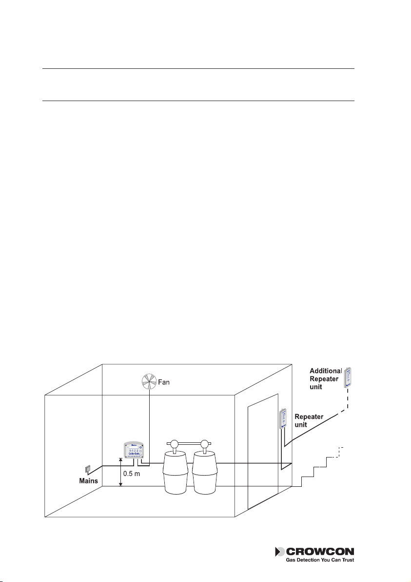
CellarSafe is a carbon dioxide and oxygen fixed monitoring system designed to
monitor gas levels in a confined space, such as a beer cellar. The system consists
of one base unit housing the gas monitoring system and is supplied with one
repeater unit to be located in a safe position outside the confined area.
Version 1 is a carbon dioxide monitor only, which looks for rising gas levels.
Version 2 is a combined system which monitors both rising levels of carbon
dioxide and falling levels of oxygen.
CellarSafe operates two alarm relays if the gas level exceeds the two pre-set
alarm levels. The output from these relays can be used to control external visual
or audible alarms, or ancillary equipment such as a fan.
CellarSafe is designed for easy installation using mains power supply and has
been designed for one-man installation. The alarm levels are factory set and the
relays are ‘fail-safe’ so the alarms will activate if the power supply fails.
The CellarSafe is supplied with one repeater unit. The repeater unit provides a
remote interface to mimic the gas monitoring alarms, fault alarm, power indica-
tor, MODE button and sounder of the base unit. A series of repeater units can
be daisy-chained together to provide an extension of monitoring system. Each
additional repeater unit is provided with a 9 m cable.
1.2 Product description
CellarSafe consists of two components: a base unit and a repeater unit.
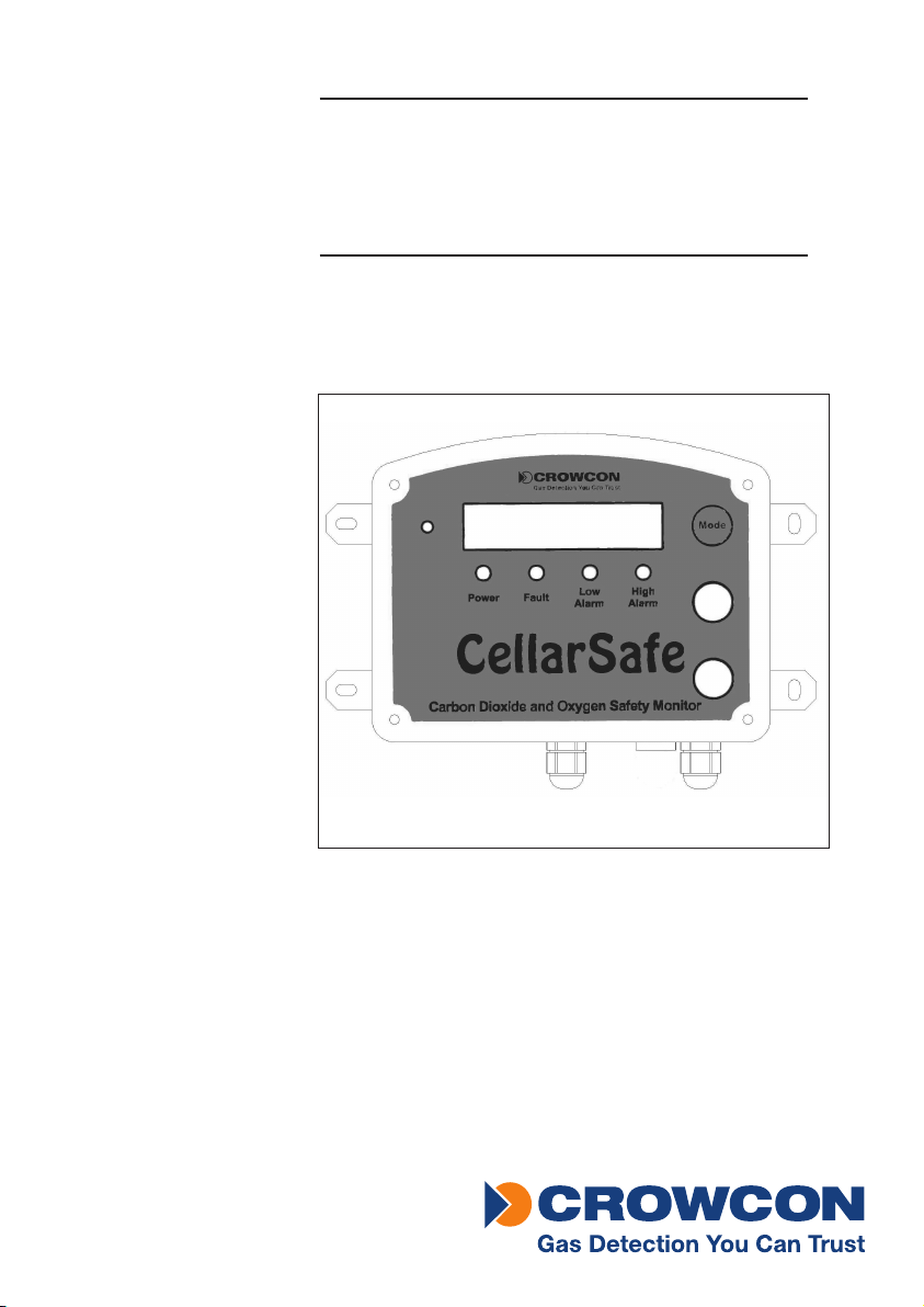
The base unit is a single shell housing the gas monitors. The display panel at the
front contains a liquid crystal display, MODE button, four illuminating LEDs and
a sounder (see Figure 1.1). Electrical connections for mains power, two relay
outputs and the repeater unit are located at the bottom of the base unit.
A 2 m mains cable and two carbon dioxide warning labels are also provided.
The repeater unit (see Figure 1.2) is supplied with a 9 m connection cable. The
repeater unit mimics the base unit but does not have the display panel.

2
Introduction CellarSafe
1.3 Normal and fault states of LEDs
The illuminating LEDs on the base unit and all repeater units indicate conditions
as below.
Flashes when the system is running:
POWER
green LED
If this LED is extinguished the system is not running,
if the LED is on continuously a fault condition is present.
If the battery backup option is fitted, the sounder will beep
every 20 seconds in the event of mains power failure.
FAULT
yellow LED
Flashes when there is a system fault.
LOW ALARM
red LED
Flashes when the low alarm level (pre-alarm) is exceeded.
HIGH ALARM
red LED
Flashes when the high alarm level (main alarm) is exceeded.
1.4 Alarm conditions for CellarSafe base
and repeater units
(Indications on some versions may differ in some details. Check specification sheet
supplied with unit)
When the low or high alarm gas level is exceeded the sounder and alarm LEDs
will operate, Table 1.1 outlines the alarm conditions.
Table 1.1: Alarm conditions for the CellarSafe and repeater units
Gas levels RELAY
INDICATION
LED
INDICATION
SOUNDER
INDICATION
Normal Not active No alarm LEDs No sound
Increasing gas levels of carbon dioxide
Gas level > Low
Alarm
Low Alarm Low Alarm LED
flashing
Long beep once
per second
Gas level > High
Alarm
Low and High
Alarm
Low and High
Alarm LEDs
flashing
Long beep once
per second

3
CellarSafe Introduction
Gas levels RELAY
INDICATION
LED
INDICATION
SOUNDER
INDICATION
Decreasing gas levels of oxygen
Gas level > Low
Alarm
Low Alarm Low Alarm LED
flashing
Long beep once
per second
followed by one
short beep
Gas level > High
Alarm
Low and High
Alarm
Low and High
Alarm LEDs
flashing
Long beep once
per second
followed by one
short beep
The MODE button is used to communicate with the CellarSafe after an alarm
is triggered. In the first instance pressing and holding the MODE button for 5
seconds will silence the CellarSafe alarm sounder, the alarm LEDs will continue
to flash in an alarm condition (i.e. gas is still present or in the case of oxygen,
depleted).
When the gas level has returned to normal the illuminating alarm LEDs will
extinguish but will reactivate the sounder and illuminating LEDs if the alarm
level is exceeded again. The CellarSafe is set to use non-latching alarms - the
LEDs will automatically extinguish when the gas level returns to normal.
If the system fault alarm is activated the CellarSafe will sound a beep twice
every second and the yellow warning light will flash. The system fault alarm will
activate if a sensor fault condition occurs.
Electrical connections for external alarm equipment are located within the main
CellarSafe base unit. One connection terminal is provided for the main alarm
and one for the pre alarm.

4
Introduction CellarSafe
Figure 1.1 The CellarSafe with carbon dioxide and optional oxygen monitors.
Figure 1.2 The CellarSafe Repeater Unit.

5
CellarSafe Introduction
1.5 Options for the CellarSafe
Oxygen monitor
CellarSafe can be fitted with an oxygen monitor to provide dual monitoring of
safe gas levels of carbon dioxide and oxygen.
Backup battery
The CellarSafe can be fitted with a backup battery providing 2 hours of backup
in the event of mains power failure.
When in backup mode the CellarSafe will emit a beep once every 20 seconds.
Up to 4 repeater units can be used with the CellarSafe base unit.
Additional repeater unit
Each additional repeater unit is supplied with a 9 m cable. For a full list of
CellarSafe units and options, see Table 1.2 below.
Table 1.2: CellarSafe units and options
ITEM PART NUMBER
CellarSafe - complete unit Contact Crowcon
CellarSafe with battery backup Contact Crowcon
CellarSafe with oxygen sensor
module
Contact Crowcon
CellarSafe with battery backup and
oxygen sensor module
Contact Crowcon
† Repeater unit including cable 99S38001
Calibration Gas CO3324
Field Calibration Unit 99S38002
†Additional repeater units come with 9 m cable.
Important
• Where battery back-up has been specified, batteries will be found
inside the unit, but not yet connected. Connect before use.
• The battery backup unit and the oxygen option contain non-
environmentally friendly elements. Please dispose in an
environmentally and safe manner or return to Crowcon for safe
disposal.

6
Installation CellarSafe
II. Installation
When carrying out any installation work, ensure that local regulations
and site procedures are followed.
2.1 General
This manual contains instructions for installing the CellarSafe base unit and
repeater unit. Before beginning installation of the CellarSafe please follow the
mounting, cabling and installation instructions, paying close attention to the
location of the base unit.
2.2 Mounting
The CellarSafe base unit is designed for wall mounting and should be located
near to the valves and manifold within the confined space approximately 0.5m
from ground level . Fixing holes are attached to the unit so that it can be
attached to the wall with appropriate screws and wall plugs.
The CellarSafe repeater unit should be mounted outside of the confined space -for
example, on the doorframe at the entrance, using the fixing brackets provided.
The height should be at eye level for ease of use.
Additional repeater units are mounted in the same way. Suitable locations are out-
side of the confined area, for example, at a secondary exit or positioned at a differ-
ent location normally occupied by staff, in a safe position, within the building.
The CellarSafe is not suitable for outdoor or hazardous environments.
Figure 2.1 Where to locate and mount your CellarSafe unit

7
CellarSafe Installation
2.3 Cabling requirements
CellarSafe is fitted with an AC plug for convenience. If, however, permanent
installation is required, it should be wired to a dedicated AC spur led from a
circuit breaker. The spur or mains plug should be fitted with a 3A fuse.
The circuit breaker should be marked as the disconnecting device for the
CellarSafe. It must comply with the relevant requirements of IEC 947-1 and IEC
947-3. These procedures ensure that the installation complies with the require-
ments EN 61010-1 (Low Voltage Directive).
The repeater unit supplied with CellarSafe does not need specialist cabling.
Each additional repeater unit is supplied with a 9 m cable as standard.
2.4 Electrical connections for external alarm
equipment
The CellarSafe has two alarm relays to which external visual and audible alarms
or other ancillary equipment, such as a fan, can be connected. An example
electrical connection is shown in Figure 2.2.
Before connecting the equipment, ensure the mains supply is switched off.
Unscrew the top cover to gain access to the screw terminal connectors on the
PCB board.
The two alarm relay connections are each marked NC (normally closed), NO
(normally open) and common (C). Use the NO and C screw terminal connectors
as shown in Figure 2.2. (L = live, N = neutral)
NOTE: The alarm relays are shown in the normally energised state. When installing
the device the normally open (NO) connection will be closed since there is no power.
Similarly, the normally closed (NC) connection will be open.
The CellarSafe can be connected to two fans, one to each alarm relay.
If the pre-alarm is exceeded the first fan will activate.
If carbon dioxide levels increase further, reaching a level that triggers the main
alarm, the second fan will activate to increase ventilation.
Dual-speed fans are also available for a similar effect: low speed and high speed
corresponding to low and high alarm respectively.
It is recommended that external equipment should be fused.
NOTE: The relay contacts must not be used to switch loads drawing more than 10 A.

8
Installation CellarSafe
Figure 2.2 Alarm relay electrical connections.

9
CellarSafe Operation and set up
III. Operation and set up
3.1 Mode button
The CellarSafe base unit and repeater unit provide a MODE button to commu-
nicate with the CellarSafe. The MODE button is used in the event of an alarm
or fault occurring, and during the self-testing procedure.
3.2 Operator display panel
The operator display panel provides a reading of the concentration of gas levels
being monitored. Carbon dioxide, CO2, is shown as a percentage concentration
level and at normal gas level (i.e. safe levels) will display 0 to 0.2%.
With the oxygen monitor option, the display will alternate between showing
the carbon dioxide gas concentration, CO2, and the oxygen gas level concentra-
tion, O2. Normal oxygen gas level concentration is 20.9%.
To activate the display backlight, press the MODE button.
3.3 Set up
The CellarSafe requires no configuration of the gas monitors or alarm set-
tings. Once the CellarSafe and repeater units are installed, you can switch on
the mains supply. The CellarSafe and repeater unit will become fully opera-
tional after a 40-second warm-up period. The alarms and sounder will operate
momentarily during this period and the operator display panel will test the
display settings.
Carbon dioxide warning labels
The CellarSafe is provided with two carbon dioxide warning labels. It is impor-
tant to fill in the contact and telephone details of the person responsible for
the safety of the confined space on labels. Affix the labels in clear, eye-level
positions near the CellarSafe unit, either at the entrance to the confined area
being monitored, or near a repeater unit.
3.4 Self-Test
A self-test routine is provided to test the CellarSafe and any ancillary equipment
attached via the alarm relays. To run the self-test routine, press and hold the
MODE button for 5 seconds.
The self-test can be initiated from the base unit or any of the repeater units.

10
Operation and set up CellarSafe
The operator display panel will illuminate and test all display segments. The unit
will enter alarm condition for a period of 10 seconds illuminating the alarm
LEDS, activating the sounder and additional ancillary alarm equipment con-
nected to the CellarSafe relays.
3.5 Alarm levels
Alarm levels vary depending on CellarSafe configuration. Please refer to the
specification sheet supplied with product, or contact Crowcon quoting the part
number of the unit.
3.6 In the event of a low or high alarm con-
dition
If the low or high level alarm levels are exceeded the CellarSafe will activate the
alarm relays, illuminate the alarm LEDs and activate the sounder on the base
unit and all repeater units.
Carbon dioxide levels exceeded (CO2): The sounder will beep once every sec-
ond
Oxygen levels exceeded (O2): The sounder will emit one long beep
followed by one short beep once every
second.
To silence the sounder, press and hold the MODE button for 5 seconds.
NOTE: CO2alarms may be subject to a 25-second time delay to prevent false alarms
when exchanging gas cylinders. Oxygen alarms are instantaneous.
In the event of an alarm condition, DO NOT ENTER THE ROOM.
Follow safety procedures as indicated on the carbon dioxide
warning labels.

11
CellarSafe Specification
IV. Specification
CellarSafe specification
Dimensions 210 x 150 x 75 mm
Weight 1.3 kg
Operating voltage 230 V, 50/60 Hz ac, 16 VA, double insulated
115 V ac option available
Operating temperature +3ºC to +50ºC (37ºF to 122ºF)
Warm up time 40 seconds
IP rating IP 65
Display Backlit LCD, 13.5 mm high digits
Instrument status indicators 2 gas level concentration alarm LEDs, red
1 fault alarm LED, yellow
1 power LED, green
1 sounder (>82 dB @ 10 cm)
Cable length 2 m
Fixing centres 4 at 192 mm x 72.5 mm
Humidity 0-99% RH non-condensing
Relay outputs SPCO 10 A, 240 V ac / 30 V dc
Repeater unit specification
Dimensions 143 x 56 x 41 mm
Weight 120 g
IP rating IP54
Instrument status indicators 2 gas level concentration alarm LEDs, red
1 fault alarm LED, yellow
1 power LED, green
1 sounder (>82 dB @ 10 cm)
Cable length 9m
Fixing centres 2 at 130mm
Operating temperature 0ºC to +50ºC (32ºF to 122ºF)
The oxygen sensor (if fitted) must be replaced every 3 years. Contact Crowcon
for part numbers and prices.

12
Troubleshooting guide CellarSafe
V. Troubleshooting guide
Problem Cause Solution
Power LED off Power not reaching
processor
Check base unit
is plugged in and
electrical supply is
switched on; check
mains fuse
Power LED on
continuously
Processor not working
correctly
Call service engineer
Fault light on and
sounder emitting rapid
beeps
Sensor fault Call service engineer
Operator display panel
displaying an error
Base unit has been
opened for servicing
or wiring with battery
option installed
Wait for 40 second
warmup period.
If error continues to be
displayed call service
engineer
12

13
CellarSafe Calibration, testing and routine maintenance
VI Calibration, testing and
routine maintenance
6.1 Functional Testing
For optimum performance, it is recommended that Cellarsafe is calibrated every
six months using the Cellarsafe calibration unit. A minimum requirement is that
units are functionally tested as described below. However, it should be noted
that full re-calibration may be required after 3 - 4 years of use.
The oxygen sensor (if fitted) must be replaced every 3 years. Contact Crowcon
for part numbers and prices.
It is also necessary to test this product at least every twelve months to ensure
that the sensors and alarms are operational. Periodic testing may be performed
simply by using exhaled breath to generate high CO2and low oxygen alarms
on units with an oxygen sensor fitted. Exhaled breath contains approximately
4% CO2and 16% oxygen, and therefore contains sufficient levels of each gas
to cause alarms on the CellarSafe monitor.
To test the alarms, blow into a plastic bag and hold the open end of the inflated
bag tightly over the sensor(s) until the alarms activate. The CellarSafe display
will show increased levels of CO2and decreased levels of oxygen (on units with
an oxygen sensor fitted), and the alarms should activate after approximately
10-15 seconds for oxygen and 25 seconds for CO2.
Alternatively, Crowcon can provide a calibration unit and calibration gas for
checking and calibrating the sensors. The following sections describe the cali-
bration procedure.
6.2 Fuses
There are two fuses fitted in CellarSafe. One fuse protects the AC inlet. The
other 2A (anti-surge) fuse is on the PCB. If either fuse requires replacement,
disconnect the unit from the mains power supply. Remove the four front-cover
fixing screws and carefully take off the cover. Then replace the fuse that has
failed with a fuse of identical specification.
6.3 Calibration
These instructions provide guidelines for the service engineer to calibrate the
CellarSafe using the CellarSafe calibration unit (Figure 6.1). The calibration unit
is suitable for all models of the CellarSafe gas monitoring system. Calibration
13

14
Calibration, testing and routine maintenance CellarSafe
requires calibration gases and a pair of bayonet calibration adapters. In calibra-
tion mode all alarms and relays are inhibited.
Calibration gases
Zero calibration is performed using 100% nitrogen. Span calibration is per-
formed using a gas mixture comprising 4.0% carbon dioxide and 20.75%
oxygen with a balance of nitrogen.
Bayonet calibration adapters
A single pipe and bayonet fitting is provided for the CellarSafe carbon dioxide
only monitoring system. The adapter for the CellarSafe carbon dioxide and
oxygen monitoring system is supplied with a “T” junction and a single com-
mon supply pipe. The flow of the calibration gas should be set to 750 ml/min
for the carbon dioxide only monitoring system, and 1.5 l/min for the dual gas
monitoring system.
6.4 Calibrating the CellarSafe gas monitor
Before connecting the Calibration Init, ensure allpower to the base
unit is off. This includes disconnecting the battery if fitted. Failure to
do so will risk damage to the unit.
Figure 6.1 CellarSafe Calibration Unit

15
CellarSafe Calibration, testing and routine maintenance
Step 1:
Connecting the Calibration Unit
1Switch off the mains supply to the CellarSafe base unit and any
ancillary equipment connected to the alarm relays.
2Remove the front cover and disconnect the battery if fitted.
3Plug the lead from the calibration unit into the connector marked
“PL2” on the printed circuit board.
4Replace the front panel of the CellarSafe base unit. Do not over-
tighten the screws.
5Reconnect the mains electrical supply.
Allow the instrument to stabilise for a few minutes. It is essential
the CellarSafe reaches the appropriate thermal equilibrium for
the gas monitors to work correctly and for the calibration to be
performed without error.
NOTE: In the unlikely event of a communication problem between the
calibration unit and the base unit , both LEDs will flicker rapidly to alert the
user. If this occurs, the system may be reset by disconnecting the mains
electrical supply for a few seconds (the battery should already be disconnected)
and re-applying the mains power.
Step 2:
Connecting the zero calibration gas
NOTE: zero gas calibration MUST BE performed before the span gas calibration.
1Insert the bayonet of the adapter into the sensor inlets by gently
twisting clockwise until they snap into place.
2Connect the other end of the adapter to the zero calibration gas
(100% nitrogen).
3Adjust the gas flow to 750 ml/min for the carbon dioxide only
monitoring system and 1.5 ml/min for the dual gas monitoring system.
Allow the system to stabilise for several minutes.
NOTE: Once connected, the calibration unit can be switched on or off by
pressing and holding the Scroll/Power button for 3 seconds.
Step 3:
Calibrating zero gas
1Press the Scroll/Power button to turn on the calibration unit. The Zero
Calibration or the Span Calibration LED will illuminate.

16
Calibration, testing and routine maintenance CellarSafe
The base unit is now in calibration mode, the operator display panel
will display alternately the internal temperature of the instrument and
the gas reading.
2If the Zero Calibration LED is not lit, press the Scroll/Power button.
3Apply zero calibration gas as described in step 2 above, and wait for
the gas reading in the operator display panel to stabilise.
4Press the Select button to start the calibration. The Zero Calibration
LED will flash to indicate that calibration is in progress.
After approximately one minute the Zero Calibration LED will stop flash-
ing and zero calibration is complete.
NOTE: The carbon dioxide reading will briefly indicate an error on the operator
display panel for a few seconds immediately after a calibration has been
performed. This is normal.
To abort the calibration for any reason press the Scroll/Power button.
5Proceed to step 4 to calibrate the span gas.
Step 4:
Calibrating span gas
1Connect the adapter to the span calibration gas.
2Adjust the gas flow to 750 ml/min for the carbon dioxide only
monitoring system and 1.5 ml/min for the dual gas monitoring system.
Allow the system to stabilise for several minutes.
3Press the Scroll/Power button to illuminate the Span calibration LED.
The base unit is now in calibration mode, the operator display panel
will display alternately the internal temperature of the instrument and
the gas reading.
4Apply span calibration gas and wait for the gas reading in the operator
display panel to stabilise.
5Press the Select button to start the calibration. The Span Calibration
LED will flash to indicate that calibration is in progress.
After approximately one minute the Span Calibration LED will stop
flashing and span calibration is complete.
NOTE: The carbon dioxide reading will briefly indicate an error on the operator
display panel for a few seconds immediately after a calibration has been
performed. This is normal.
To abort the calibration for any reason press the Scroll/Power button.
Table of contents