halo connect IN-100CM User manual

USER MANUAL
Keep this manual in the vehicle for future reference.
Read this manual before using this product. Failure to follow the
instructions and safety precautions in this manual may result in
serious injury or death.
IN-100CM


SAFETY WORDS AND SYMBOLS
Please pay attention to special symbols used through this manual
to convey important information. Hazard signal words such
as WARNING, CAUTION, or NOTICE are used throughout this
manual. Information accented by these words indicates a point of
emphasis and importance. The following denitions comply with
ANSI Z535.6 and indicate the use of signal words as they appear
within this manual.
This is the safety alert symbol. It is used to
alert you to potential physical injury hazards.
Obey all safety messages that follow this
symbol to avoid possible injury or death.
WARNING indicates a hazardous situation
that, if not avoided, could result in serious
injury or death.
CAUTION indicates a hazardous situation
that, if not avoided, could result in minor or
moderate injuries.
NOTICE is used to address practices which
could result in damage to equipment or
property.
IMPORTANT SAFETY INFORMATION
The Halo Connect Gateway and its components should be
installed and maintained in accordance with the instructions in
this manual. Proper installation of the Halo Connect is critical to
ensure safe use of the device. Failure to do so may result in injury
or death, damage to equipment, material or property. Carefully
read, understand and follow all safety related information within
this manual.
Exercise caution when working with the vehicle
power sources to avoid inury.
3

Contents
3 Safety
3 Important Safety Information
3 Safety Words and Symbols
5 Introduction
6 Getting Started
6 System Components
6 Installation Tools
7 Halo Connect Installation
7 Afx gateway ID sticker to vehicle
8 Determine where to put the Gateway
9 Locate power source and ground
10 Attach TPMS antenna to vehicle
10 Attach GPS antenna to vehicle
11 Attach Gateway to vehicle
11 Connect cables to Gateway
11 Conrm Gateway power
12 Install TPMS sensors
12 Pair Gateway using mobile app
13 Regulatory
Customer Support
Phone +1 (650) 741-3231
Website www.aperiatech.com
Sales [email protected]
4

SYSTEM
Halo Connect Web Services
Web Services give you full control over your data, alerts, and
reports. All of the issues in the eet, active and historical, are
easily viewed and organized, using the systems that eets are
most comfortable with, such as email. For each vehicle issue,
the portal gives recommended actions for resolution. For an
understanding of the bigger picture, we distill the data into
analytical reports to visualize the trends in the eet.
Halo Connect Gateway
The Halo Connect Gateway is comprised of a durable enclo-
sure that is secured in the cab of the vehicle. It uses a built-in
LTE cellular connection to send data to the cloud, TPMS to talk
to the sensors, and a bluetooth connection to talk to mobile
devices. It also has GPS, which noties the location in which a
vehicle issue transpired.
Halo Connect mobile application
The Android mobile application makes installation and congu-
ration of the Gateway and sensors seamless, requiring just two
data matrix scans per install. The app allows you to choose
between various truck congurations, register the vehicle in
our system, and add or replace sensors.
5

Getting started
INSTALLATION TOOLS
• 5/16" Hex Head Screwdriver
• Torx Screwdriver (or Other, as needed, to access fuse panel)
• Wire Crimper
• Cutters (for cutting zip ties)
• Isopropyl Alcohol and Wipes
MOUNTING PARTS
• #10 x 1" Hex Head Screws (5/16" Hex Head)
• UV Stabilized 6" Zipties
• 1" x 1" Velcro squares
SYSTEM COMPONENTS
• Pack of Halo Connect sensors
• Power cable with mini fuse connector
• TPMS cable
• TPMS antenna
• Cellular antenna
• GPS antenna
HALO Connect Gateway
6

HALO CONNECT INSTALLATION
1. AFFIX GATEWAY ID STICKER TO VEHICLE
Select an easy to access location to permanently attach the
gateway ID sticker inside the vehicle.
The gateway ID sticker contains gateway identication infor-
mation used to pair the gateway when using the phone app.
and during customer service calls.
Aperia recommends placing the sticker in the door jamb.
7

8
BEST GATEWAY LOCATION
Inside cab of vehicle.
Behind and below seat.
Should be installed with mini-
mum distance of 20 cm away
from driver and passengers.
HALO CONNECT INSTALLATION, CONT'D
2. Determine where to put Gateway
Select a location to permanently attach the Gateway box inside
the cab of the vehicle.
Consider that the Gateway will have power and antenna ca-
bles attached to it that need to be routed to locations specied
in later steps. See step 5 for further instructions on attaching
the Gateway to the vehicle.
Other Gateway placement considerations include:
• Gateway should be accessible for maintenance.
• Gateway should be installed with minimum distance of 20 cm
away from driver and passengers.
• Does not interefere with passenger access or storage.
• Protected from spills and passenger movement in vehicle.
• Does not interfere with seatbelts.
• Allows for permanent attachment using self tapping screws
or other secure attachment based on eet preference.
Before attaching the Gateway box to the vehicle
review the entire install procuedure and ensure the antenna
and power cables are safely routed to the recommended
locations.

9
HALO CONNECT INSTALLATION, CONT'D
3. locate power source and ground
In order for the vehicle's tires to be monitored 24 hours, the
Gateway power cable should be connected to a 24 hour con-
tinous 12-20V power source and be securely grounded to the
vehicle chassis.
A mini add-a-fuse connector is included with the Gateway. If
using this add-a-fuse, locate the vehicle's fuse box and select
the power and ground locations.
If you are using a different power connection be sure to add a
fuse to the positive power cable.
The positive wire of the power cable must be
fused. An un-fused power cable may over-heat and lead to a
vehicle re.
Use a voltmeter to test the power source and ground
with the ignition on and off to ensure that the voltage of the
chosen fuse slot is correct and continuous..
1
Fuse Rating: 1 Amp
10
HALO CONNECT INSTALLATION, cont'd
4. attach TPMS antenna to vehicle
The TPMS antenna must be placed outside on the rear of the
vehicle and the cable needs to be routed back to the Gateway.
Find an opening in the cab to route the antenna cable from the
Gateway to the outside of the vehicle.
Once the cable is routed, attach the TPMS antenna to the end
of the TPMS antenna cable and securely attach the TPMS an-
tenna to the outside of the vehicle using at least two zip ties.
5. attach GPS antenna to vehicle
The GPS antenna must have a clear view of the sky to operate
properly. Remove adhesive protector from GPS antenna, and
place the antenna on the dashboard inside the cab. Route the
cable back to the Gateway.
Avoid creating a tripping hazard when routing
the TPMS antenna on the exterior of the vehicle.
Expected vehicle operation must be considered
when routing the TPMS antenna to avoid damage to the
antenna. Make sure the antenna is routed so it won't be
excessively stretched or cut when the vehicle turns or when
the suspension is compressed. Protect the antenna from heat
sources when routing.
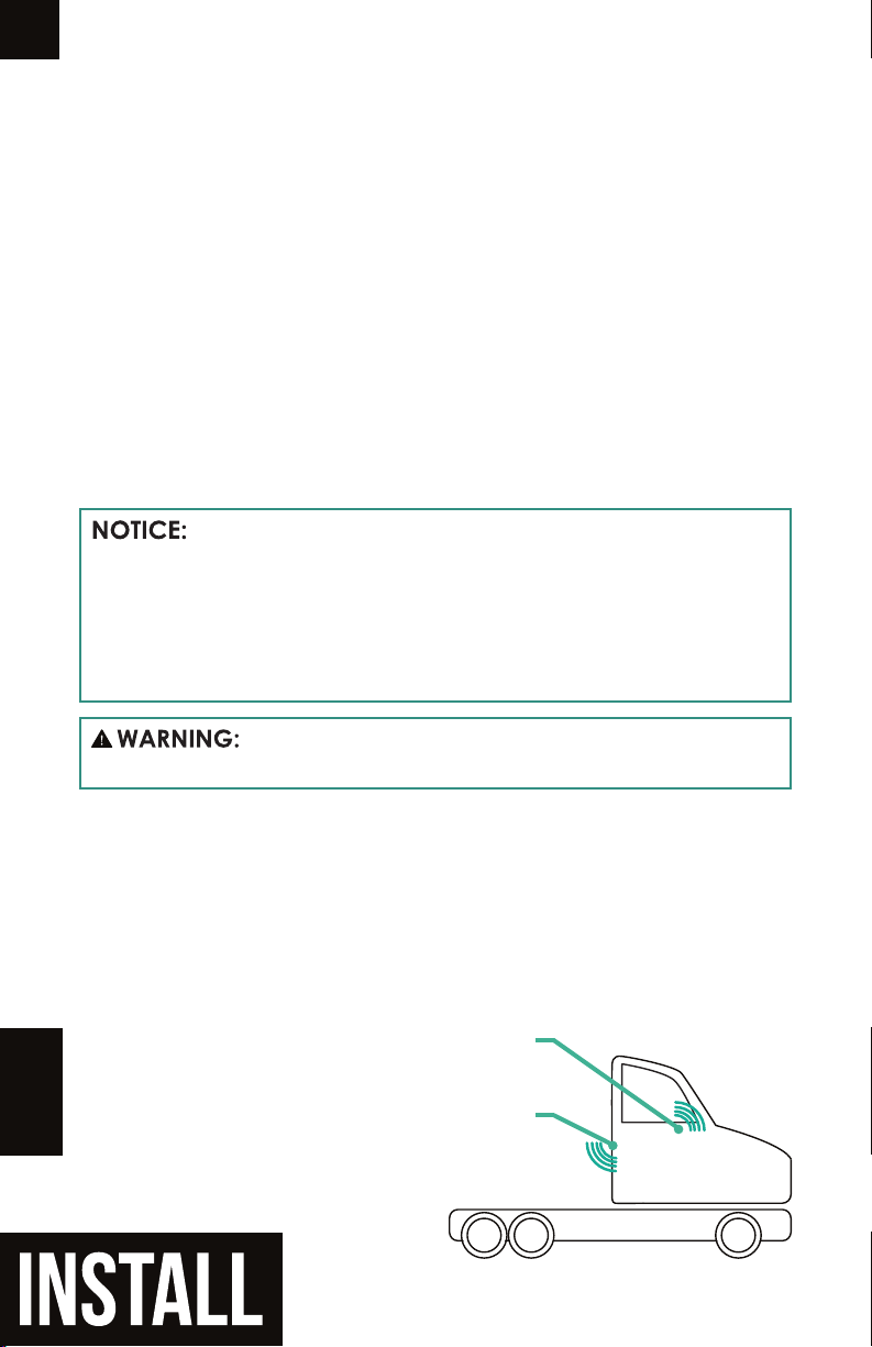
BEST GPS LOCATION
On the dashboard with a view of the sky
BEST TPMS ANTENNA LOCATION
On rear of exterior of vehicle, pointing downward
Table of contents


