Halton KVE (SJ-SK) User manual

Operators Manual
Manual provides
Installation, Operation, and Maintenance Instructions
Models : KVE (SJ-SK) KVC (SJ-SK), KVW (SJ-SK),
KVR, KVO, KVL and KVM
SWR / EO / DW / CH
SWS / SBS / SIR5

CJOM/2009/rev2/EN
2
GENERAL DESCRIPTION
All Halton Capture Jet® hood systems provide solutions for a variety of commercial foodservice ventilation applications
over virtually any cooking process. Halton’s Capture Jet® technology gives the most efcient system on the market.
To achieve the optimum performance from your hood system (s) please use the following guidelines provided within
the pages of this Installation, Operation, and Maintenance Manual.
In addition to this information our ofces or local representatives are available at any time to provide additional
technical support for products, applications, installation, commissioning or in any aspect that you may have.
RECOMMENDATION
Upon receipt of the Halton hood (s), inspect unit (s) immediately for any shipping damage and notify carrier immediately
if damage is found. Halton will not accept responsibility for any shipping damage. All systems are thoroughly inspected
before leaving our factories, however Halton will assist in ling a claim if needed.
GENERAL INSTALLATION
It is the responsibility of the installing contractor to see that the system installation is completed in accordance with the
project plans and specications and that it meets all specic requirements of local code ofcials. The local authority
having jurisdiction could over rule some of the installation details written in this manual. The installation shall be in
accordance with NFPA-96. All electrical systems shall be installed following local and national codes.
The owner and/or operator should be instructed in the proper operation, care and maintenance of the system.
If questions or complications should arise during the installation of the Halton hood (s) that cannot be solved using the
instructions provided please contact the Halton ofce at 1-800-442-5866, or (1-800-4-HALTON).
Note: There are no instructions contained within this manual for installation or maintenance of fan packages.
**See appropriate manufacturers manual for detailed instructions.
EXHAUST AIRFLOWS
Because the listed exhaust airows rates were established under controlled laboratory conditions, please see
submittal drawings or contact the manufacturer for exhaust air ow rates.

CJOM/2009/rev2/EN
3
INSTALLATION INSTRUCTIONS
1. Inspect the crating carefully. If there are signs of damage, call the freight carrier before uncrating the units.
Carefully uncrate the units. Check all local codes prior to installation, special requirements may be necessary
depending on local building material construction.
** Important note ** Do not leave unit (s) exposed to extreme temperatures for an extended period
of time, this may cause the protective PVC coating around the unit (s) to become very difcult to
remove.
2. Position the hood near the actual installation site. In case of multiple hoods, check the engineered set of
drawings for locations. Pay close attention to collar sizes and re protection layouts, matching the hood
systems to the correct location shown on the drawings provided.
**Check item numbers on crates / hoods vs. drawing item numbers.
3. Once the hood is carefully removed from the shipping crate and set in position, the unit is now ready for
installation. If Halton Company has supplied a backsplash assembly, then the splash assembly should
be installed rst, for installation procedures. (See pg. 4)
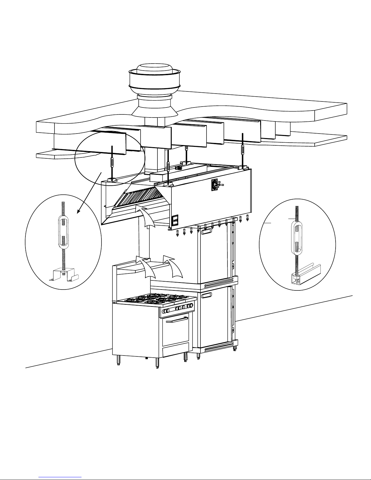
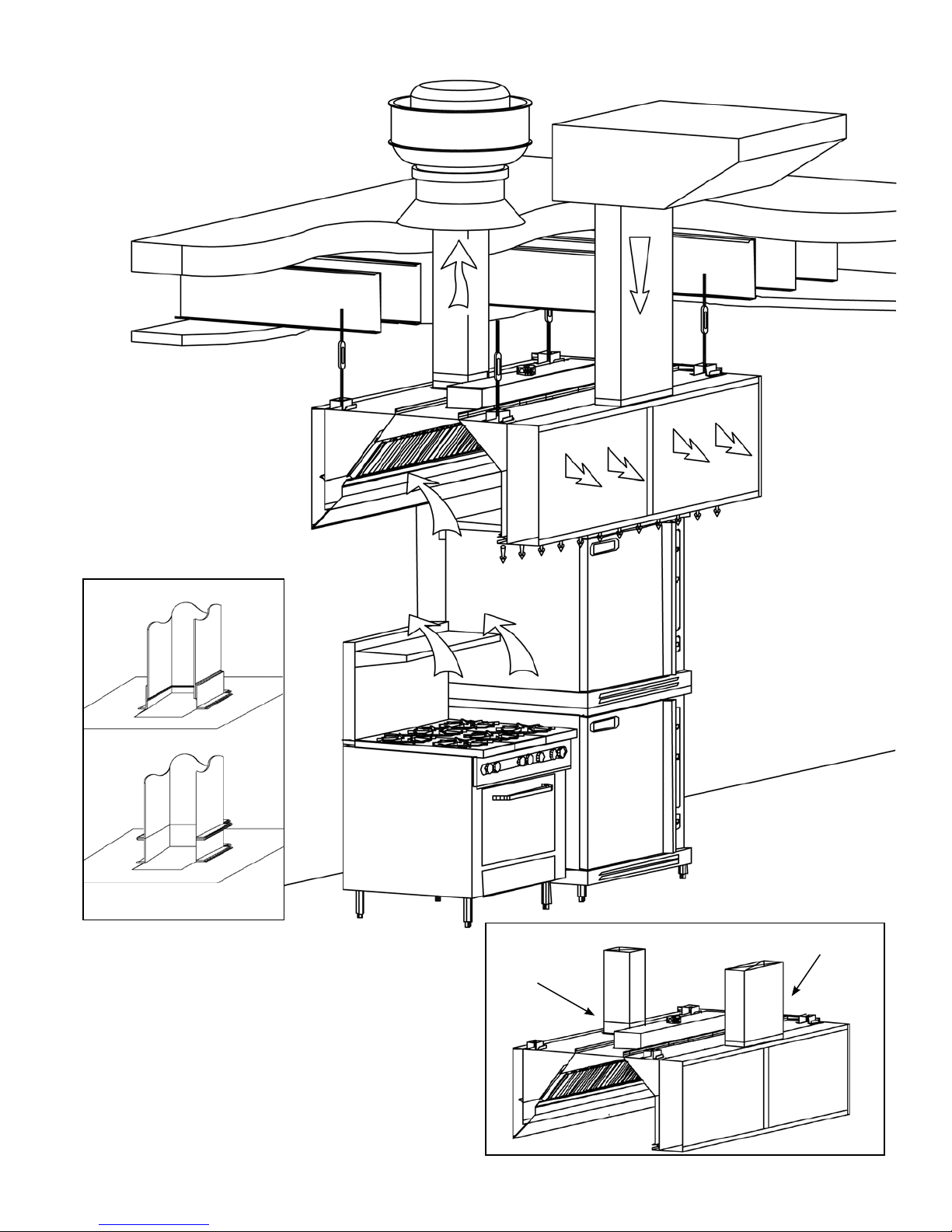
4. Hang the hood using ½” threaded rods by attaching the rods to the hood through the hanger brackets that are
welded to the top of the hood. Use of turnbuckles will make nal adjustment easier. Standard hanging height
for canopy hoods ranges from 78” min. to 84” max. above the nished oor (per local codes having
jurisdiction). **Noted in installation instructions - (see pg. 6).
**All typical installations for Capture Jet® series hoods shown on pages 18-22.
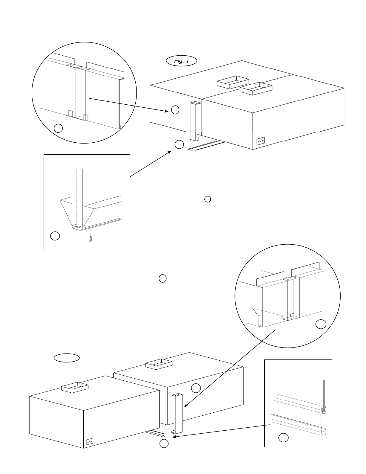
5. If Closure Panels are supplied by Halton (see pg. 8) for details on the installation.
6. For multiple hoods end to end, or back to back (see pg. 7) for Installation of Splice Strips and U-Channels.
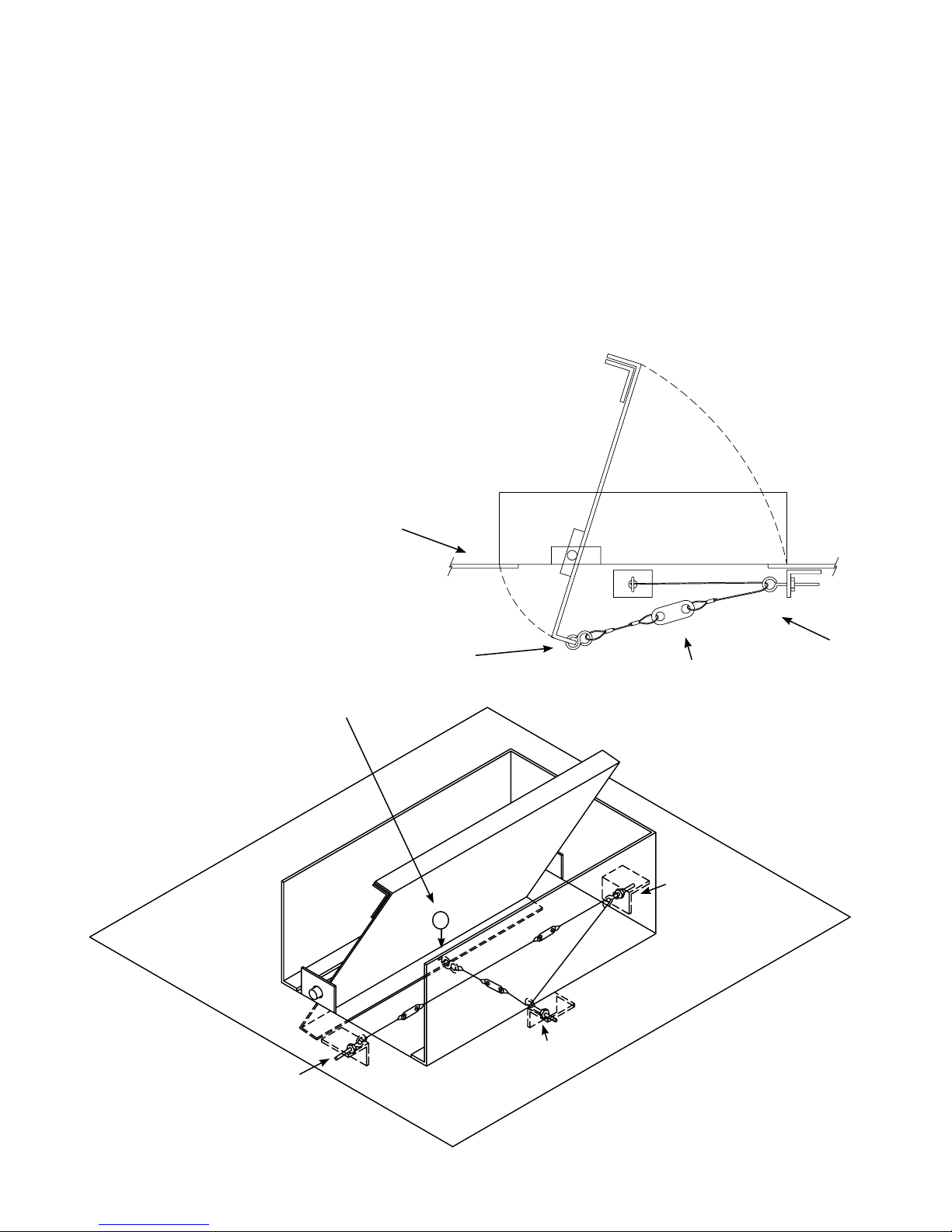
7. For hoods equipped with a supply re damper, it is very important to make sure that the re damper is set in an
open position before connecting the supply duct.
For units with exhaust re dampers, (see pg. 9), or supply re dampers, (see pg. 10) for installation
details.
8. Electrical circuits should be connected according to standard switch panel wiring diagram, shown on (pg. 11).
For Halton Capture Jet® series hoods, a typical wiring diagram is shown on (pg. 12).
9. Grease lters and grease cups must be installed in place before start-up.
10. Install 100 watt maximum light bulbs in standard incandescent lights or uorescent bulbs (36” L or 48”L) in
uorescent lights. **Note: Halton does not provide bulbs.
11. Protect the hood from damage under normal job site conditions, until all work is complete and system is ready
to be put into operation.

CJOM/2009/rev2/EN
4
OPERATION OF SYSTEM
1. After installation is complete, it will be necessary to check and balance the airows. On the Capture Jet®
line of hoods, Halton supplies T.A.B. (testing and balancing) ports for measuring the pressure drop. These
ports are located on the inside of the canopy on each plenum. (Exhaust and Capture Jet®).
For details on their use (see pg. 13). For hoods without ports, use of standard practices (duct traverse /
average velocity / etc) for measuring airows will be required.
**It is very important that the fan for the Capture Jet® air be balanced according to specications.
See the job specic information for required airows. Adjustments to the Capture Jet® fan can be made
with the speed controller supplied with the fan. This speed controller will be mounted inside or on top of the
hood, or mounted in an electrical enclosure.
Information regarding the fan and speed controller (see pg. 12).
2. Each Halton Capture Jet® hood system will have a “KSA” lter remover (model KFR). The “KFR” will be
packaged separately, inside the hood, the box will be labeled “Attn: Kitchen Mgr. “ Model KFR instructions on
(pg. 14). The KFR will assist in removal of the lters for assembly and cleaning.
3. After the exhaust and supply airows have been properly balanced, a nal inspection should be made to
ensure proper system operation.
HOOD MAINTENANCE
1. Clean the hood canopy inside and out as needed with mild soap and water. Never use harsh or abrasive
cleaners on Stainless Steel or Painted surfaces, making sure to wipe clean all interior and exterior
surfaces of the hood including the light xtures.
** Never clean the hood canopy when any of the surfaces are hot.
2. Clean the lters and grease cup(s) daily, rst washing by hand, and then placing them into a dishwasher or
by steam cleaning.
** Handle the Grease lters carefully **

CJOM/2009/rev2/EN
5
Screw through top of
ange to wall.
*( screw head will not
interfere with hood)
Screw backsplash
to wall or attach with
adhesive.
Halton canopy hoods
should be installed
from 78” min.- 84”
max. above the
nished oor.
1” Insulated Backsplash Assembly
Flat Sheet Backsplash Assembly

CJOM/2009/rev2/EN
6Typical Hood Installation Details
Hang the hood using 1/2” threaded rods by attaching the rods to the hood through the hanger brackets (as shown)
which are welded to the top of the hood, using the turnbuckles will make nal adjustments easier. Hanging height of
Canopy hoods should be per local building codes, verify with “Authority Having Jurisdiction” for hanging height
in your project location.
Standard hanging height is 78” minimum to 84” maximum above the nished oor.
Hanger Bracket / Turn
Buckle Detail -
Welded to top of hood.
18 ga. material All
Thread (By Others)
*Optional Unistrut / Turn
Buckle Detail

CJOM/2009/rev2/EN
7
Supply Duct
Supply Duct may be attached to supply collar with sheet
metal screws or pop rivets and sealed with duct tape.
Screws or Rivets are not to interfere with the operation of the
re damper (if equipped).
Recommended
Exhaust Duct
Installation Details
Exhaust Duct
per code
Supply
Duct
Exhaust
Duct Options Available

CJOM/2009/rev2/EN
8Splice Strip / U-Channel Assemblies
U-Channel
AA
B
Splice Strip:
For hoods placed back to back: Slide Splice Strip B over bottom of hoods
rst, then over top, secure by welding together.
For hoods placed end to end: Slide over bottom front edge rst then over
top, secure by welding together, or as an option using screws for models with
supply plenum.
Fig. 1
Fig. 2
U-Channel:
For hood models that are placed back to back (as shown in Fig. 1):
Slide the U-Channel A up over the back of the hood systems, and secure
with sheet metal screws.
For hood models that are placed end to end (as shown in Fig. 2):
Pry apart the U-Channel at one end and slide over the end panels, fastening
in place, tting around the perimeter of the hood systems.
Installation Notes:
B
Splice Strip
BSplice Strip
Hoods shown end to end
Hoods shown back to back
Fig. 1
A
B
A
U-Channel

CJOM/2009/rev2/EN
9
Installation Notes:
1) Panels “A” and “B” are to set on top of the hood perimeter.
*Vertical ange at the bottom of closure panel and vertical
ange on top of hood should line up.
2) Hammer clips “C” over the two vertical anges.
3) Attach panels “B” to wall using appropriate hardware “D”.
4) Slide front panel “A” into place.
5) Attach panels “A” and “B” together using hardware “E”
*(Hardware not provided by Halton)
B
B
A
C
C
C
C
B
A
B
D
D
Closure Panel Assembly
E
E

CJOM/2009/rev2/EN
10 Exhaust Fire Damper Assembly
1. Remove grease lters.
2. Uncoil Stainless Steel cable attached at clip (A)
3. Thread end of cable from eyebolt at clip (A) going through eyebolt at clip (B), then thread through eyebolt
at clip (C).
4. Hold re damper in maximum open position to attach “S” hooks at point (D), close “S” hooks to secure.
5. For nal adjustment of re damper, tighten eye bolts at clips (A), (B) and (C) so that cable has no slack,
and assure maximum open position is obtained.
** (Access to re protection exhaust duct nozzle to be provided by others)
Fusable Link
Eye bolt
Clip (A)
Clip (C)
Clip (B)
D
Optional in Models : SWR / SWS / SIR5 / DW / KVE / KVC / KVW
**Located in below detail
as (D).
Secure “S” hook to damper
as shown.
The collar is supported
by a 1/2” ange located
on the inside perimeter
of the damper.

CJOM/2009/rev2/EN
11
Supply Fire Damper Assembly
1. It is important that damper is set in open position before installing supply duct.
2. Hold damper in maximum open position, fasten “S” hook at end of stainless steel cable onto
the hole located in the middle of the supply re damper ange, closing ends of the “S” hook to
secure.
3. On nal adjustment of the supply re damper, tighten cable using eyebolts to assure maximum
open position.
Optional in Models: SWR / SWS / SIR5
Eye bolt
Fusible Link
Secure “S” hook to damper
as shown.
**Located in below detail
marked (D).
D
The collar is supported
by a 1/2” ange located
on the inside perimeter
of the damper.

CJOM/2009/rev2/EN
12 Standard Switch Panel Wiring
*(For Hoods not equipped with Capture Jet®)
---- ---- ---- ---- ----- By Electrician
------------------------------ By Halton
Wires Numbered as shown in junction box.
- #5

CJOM/2009/rev2/EN
13
Capture Jet® Fan Installation
Typical Wiring of Capture Jet® Fan
Models KVE, KVC, KVR and KVW are
equipped with an Integrated Capture Jet® fan
package, as shown above.
T.A.B. Ports
KSA Filter
Integrated Capture Jet ® fan
(Optional)
(Standard)
Speed
Controller
5 AMP Speed Controller wired on
top of hood or located in the Control
Panel
Capture Jet®
Plenum
Capture Jet®
Fan
This style is standard for Model KVL
Top of Hood
Front of
Hood
w/ Halton supplied Switch Panel

CJOM/2009/rev2/EN
14
Exhaust T.A.B. Readings vs. Airflow
0.00
0.05
0.10
0.15
0.20
0.25
0.30
0.35
800 1050 1300 1550 1800 2050 2300
Airflow (cfm)
T.A.B. Reading (In. WC)
This example shows how to determine the correct T.A.B.
port reading for the exhaust hoods.
In this example, a design airow of 1700 cfm is selected
from the Airow axis, and a vertical line is drawn up to
the T.A.B. pressure curve for this hood.
A horizontal line is then drawn for the T.A.B. pressure
curve to the T.A.B. reading axis on the left-hand side of
the chart and the corresponding pressure is read off the
chart as 0.19 inches of Water Column.
Capture Jet® T.A.B. Port Readings
Hood Model Design T.A.B. (inches WC)
KVE/KVC 0.25
KVW 0.25
KVR 0.25
KVL 0.29
T.A.B.™ - Testing and Balancing Ports
The Capture Jet® and exhaust air flows are easily and
accurately determined by measuring the pressure
difference from the T.A.B. (Testing and Balancing)
ports mounted in each plenum. The corresponding
air flows can be read from the diagram provided.
To properly measure T.A.B. port readings use a
magnehelic gauge or digital manometer and for
exhaust plenum reading hookup hose from negative
connection on instrument to T.A.B. Port on exhaust
plenum. Leave positive connection on instrument
open to atmosphere.
**** It is very important the cooking equipment is in operation to create a thermal plume, prior to the air balancer, to be able
to use the T.A.B. ports.
****For accurate results, the balance contractor should receive a copy of the job specic hood plans with the design T.A.B.
readings from the hood supplier prior to balancing.
Closeup view
of T.A.B. Port
Measured Pressure

CJOM/2009/rev2/EN
15
Halton AccuFlow
Overview
The AccuFlow by Halton is a Bluetooth equipped device intended to monitor the exhaust airflow rate
of Halton Capture Jet hoods and alarm kitchen staff if the hood is above or below design. The device
(shown below in Photo 1) has two taps (Photo 2) that are connected to the exhaust hood to monitor
the differential pressure between ambient air and the exhaust plenum; the T.A.B Port reading.
AccuFlow installs in Capture Jet plenum for easy viewing and access. The device shares an electrical
circuit with the Capture Jet fan.
Photo 1 – Halton AccuFlow
Photo 2 – AccuFlow Pressure Taps
Exhaust airflow rate is determined in the same fashion as other Halton Capture Jet hoods; each
hood has a unique K-Factor dependent upon model. The actual airflow is compared to the design
value and an alarm is enabled if airflow is above or below the specified range.
Connects to ambient (room) air
Connects to T.A.B. port
Plastic tubing connected to (-) port of
Accuflow device

CJOM/2009/rev2/EN
16
Operation
Each AccuFlow is programmed at a Halton Company manufacturing facility. To program the device,
the Bluetooth feature is enabled and personnel input necessary parameters. Programming can be
completed with a Windows Mobile enable smart-phone (PDA) or PC with the required software installed.
Programmed values include: Design Airflow, High Airflow Delta, Low Airflow Delta and K-Factor.
Design Airflow is determined using the Halton HELP software and the Low and High Airflow Delta are
defined as +/- ten percent of design airflow. K-Factors have been determined by Halton Research and
Development personnel.
Bluetooth capability also allows an Authorized Service Agent to determine the airflow of an exhaust
hood on site if an alarm is present. This information can be conveyed to Halton personnel for
troubleshooting.
Alarms
Alarms are enabled when design airflow is above or below ten percent of design airflow. An alarm is
visible on the front of the Accuflow, see Photo 3 below.
Photo 3 – AccuFlow Alarm Location
Indications of alarm status (under or over design) are printed on the device. If the LED indicator is
steady, the hood is at design airflow. Alarms are differentiated by the number of blinks per second;
1 blink per second indicates the hood is under design, 2 blinks per second indicates the hood is over
design.

CJOM/2009/rev2/EN
17
Troubleshooting AccuFlow
Problem Probable Cause Solution
No lights Illuminated on
AccuFlow device
Loose or improper electrical
connections
- Verify or reconnect electrical
connections
Low airflow alarm
-Not reaching design airflow
-Plastic tubing disconnected
from Accuflow device or TAB
port
-Broken plastic tubing
-Dirty or plugged TAB port in
exhaust plenum
-Increase fan speed
-Reconnect
-Replace tubing
-Clean TAB port
Failure Bad Device - Replace

CJOM/2009/rev2/EN
18
To assemble the KFR lter remover:
Screw together stainless steel pipe, coupling, and bracket and tighten all joints.
(as shown in above picture)
KSA Filter Removal
with Model KFR
To remove lter:
Insert bracket into the inside KSA lter slots, and lift
upward until lter slides out of plenum.
To install lter:
Place lter on KFR (lter removal tool) bracket, raise lter
into place inside exhaust plenum. Slide upward until
top lip of lter is locked into place and bottom lip of lter
slides in place inside the exhaust plenum.
*** It is very Important to lock top lip of lter in place
in installation as shown in reference drawing.
To remove
lter
To install
lter
Filter Installation and Removal
16 ga. S.S. Bracket
S.S. Coupling
S.S. Pipe

CJOM/2009/rev2/EN
19
Round / Oval Style Hood Systems
Model KVR & KVO
45º min
lter angle
24”
minimum
height
Model KVR Round and Oval hoods can be shipped in pieces for eld assembly. If pieces are
shipped loose, parts will be marked for easy assembly, and an Operation and Installation, and
Maintenance manual will be provided.
3D Plan view of round KVR 3D Plan view of oval KVR
Cross section of KVR

CJOM/2009/rev2/EN
20 Model EO
Typical Installation
KSA Filters
Incandescent
Lights
Incandescent
Lights
Filters
78”-84” A.F.F.
Standard
**(Verify with Authority in project
location for min. hanging height)
Exhaust Air
UL listed upblast fan for restaurant
cooking appliances
16 ga. duct all welded
per code
Model DW
This manual suits for next models
13
Table of contents
Other Halton Ventilation Hood manuals

Halton
Halton MM1 Series User manual

Halton
Halton Capture Ray KVE-UV User manual

Halton
Halton Capture Jet KVE-WW User manual

Halton
Halton Rex Expander Product manual

Halton
Halton EcoloAir 3000CFM User manual

Halton
Halton KVE-UV User manual

Halton
Halton KVE-WW User manual

Halton
Halton Capture Jet KVESJ User manual

Halton
Halton ECOV-10 Specifications

Halton
Halton KVF Capture Jet Instruction Manual