Hamamatsu Energetiq LDTLS TLS-EQ-9 User manual

Model TLS-EQ-9
Laser-Driven Tunable Light Source
LDTLS®
Operation Manual
Revision 3, June 2022
Part Number DOC-9220

©2022 Energetiq Technology, Inc. All rights reserved.
Energetiq products are covered by the following patents: US 7435982, 7786455, 8525138,
8969841, 9048000, 9185786; Japan 5410958, 5628253; Korea 10-1507617; UK
GB2450045. All technical information, including drawings, schematics and specifications
contained in this document are the property of Energetiq and shall not be reproduced in
whole or in part without the written consent of Energetiq. The content of this document is
subject to change without notice.
Energetiq Technology, Inc.
205 Lowell St.
Wilmington, MA 01887
Phone: +1 781-939-0763
Fax: +1 781-939-0769
Email: info@energetiq.com
Website: www.energetiq.com


Table of Contents
1. Introduction ............................................................................................................................................ 1
2. Safety instructions.................................................................................................................................. 1
2.1. General Precautions ..................................................................................................................... 1
2.2. Definition of equipment and document symbols and designations............................................... 2
2.3. Laser Information .......................................................................................................................... 3
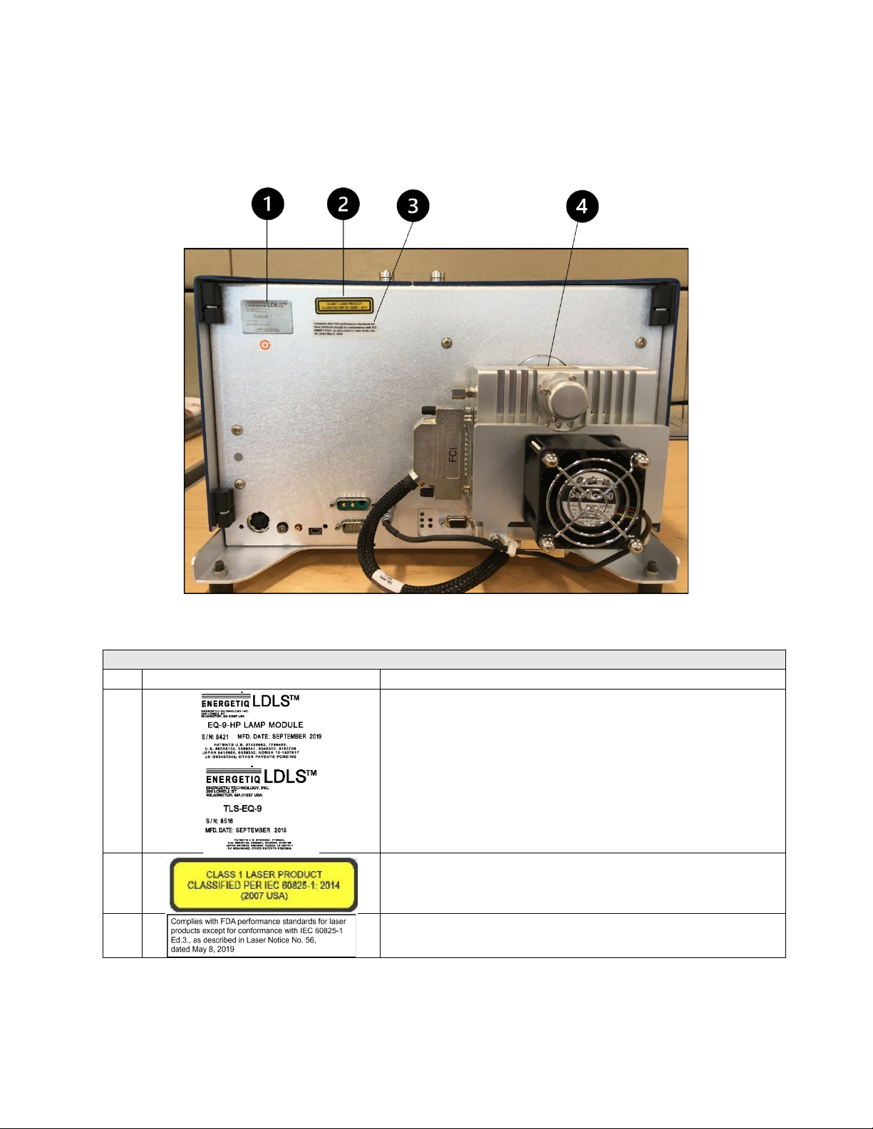
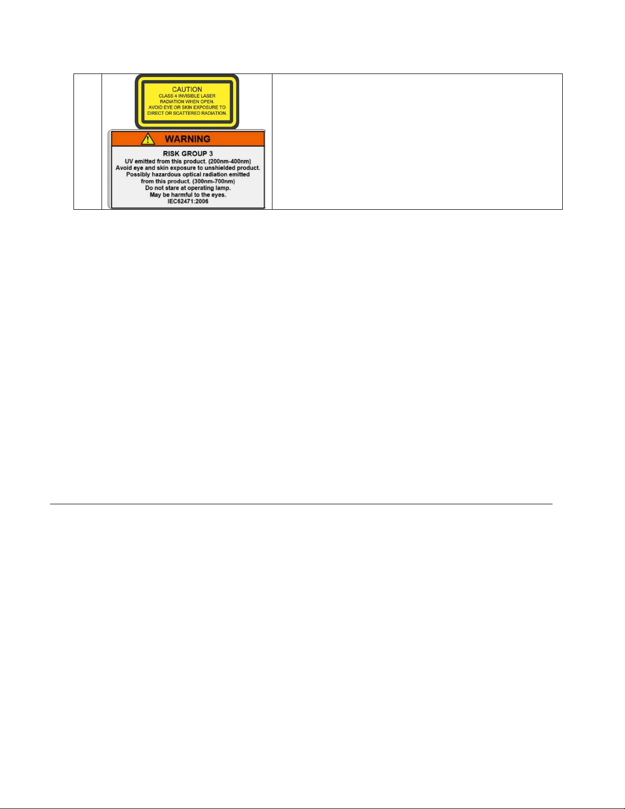
2.4. Labels and Safety Notification....................................................................................................... 4
2.5. Safety Interlocks............................................................................................................................ 5
2.6. External Interlocks......................................................................................................................... 5
2.7. Correct disposal of the unit ........................................................................................................... 5
3. Preparation of System ........................................................................................................................... 5
3.1. Unpacking guide ........................................................................................................................... 5
3.2. System Description ....................................................................................................................... 6
3.2.1 TLS-EQ-9 Main Housing ........................................................................................................... 6
3.2.2 Internal Components ................................................................................................................. 8
3.3. Optical Performance ..................................................................................................................... 9
3.4. Physical Specifications.................................................................................................................. 9
3.5. Utility requirements ....................................................................................................................... 9
3.6. Remote Interface........................................................................................................................... 9
3.7. External interlock connection ...................................................................................................... 10
4. TLS-EQ-9 Setup .................................................................................................................................. 10
4.1. Connections ................................................................................................................................ 10
4.1.1 Electrical Power....................................................................................................................... 10
4.1.2 Purge Gas ............................................................................................................................... 10
4.1.3 RS-485 Interface ..................................................................................................................... 10
4.2. Installation Procedure ................................................................................................................. 11
5. TLS-EQ-9 Operation ............................................................................................................................ 12
5.1. Startup......................................................................................................................................... 12
5.2. Stopping ...................................................................................................................................... 12
5.3. Monochromator Interface ............................................................................................................ 12
5.4. Changing Monochromator slits ................................................................................................... 13
6. Service Requirements.......................................................................................................................... 13
7. Maintenance and Troubleshooting Guide............................................................................................ 14
7.1. Maintenance................................................................................................................................ 14
7.1.1 Optical Alignment .................................................................................................................... 14

7.1.2
Procedure
................................................................................................................................. 15
7.2. Fault Indicator Block Diagram ..................................................................................................... 20
8. Warranty .............................................................................................................................................. 21
9. Appendix .............................................................................................................................................. 21
9.1. Dimensional Drawings ................................................................................................................ 21
9.2. Environmental Requirements...................................................................................................... 22
9.3. I/O Connector Pin Assignment.................................................................................................... 22
9.4. RS-485 Interface Pin Assignment............................................................................................... 22
9.5. Remote Interface Schematic....................................................................................................... 23
9.6. Serial Interface Commands......................................................................................................... 23
9.7. Revision History .......................................................................................................................... 25

1
1. Introduction
The TLS-EQ-9 Laser Driven Tunable Light Source is a compact, highly stable tunable light source. It
utilizes the Energetiq EQ-9 Laser Driven Light Source® as a broadband light source. A monochromator is
used to select the desired output wavelength. The monochromator output is fiber coupled to the TLS-EQ-9
output.
The TLS-EQ-9 system consists of a main housing that includes the internal Lamp Controller Unit,
Monochromator, and installed lamp. Connected to the main housing are the Remote Control unit, Lamp
Power Supply, Monochromator Power Supply, and interconnecting cables
For additional information contact Energetiq Technology Technical Support Services at +1-781-939-0763
X111 or e-mail: EUVproductsupport@Energetiq.com
2. Safety instructions
2.1. General Precautions
The output beam from the TLS-EQ-9 should be blocked when not in use with an electronic shutter or other
appropriate beam blocking device. Due to the possibility of generating ozone with some models of TLS-EQ-
9 when ambient oxygen is exposed to short wavelength light, the beam should always be enclosed in an
appropriate beam pipe, tube, or enclosed space. We suggest purging any beam transport space with dry
nitrogen gas.
The TLS-EQ-9 source must also be cabled correctly and connected to a power source with a protective
earth ground prior to operation.
Refer to the Installation section of this manual in Section 4 for details of the facilities connections.
There are no user-serviceable parts inside the TLS-EQ-9. For any problems encountered during operation,
please contact Energetiq Technology for assistance. If there is a component failure, do not attempt to
open the Power Supply Controller or Lamp House enclosure of the TLS-EQ-9.
The TLS-EQ-9 utilizes a quartz lamp containing a high-pressure gas fill. Explosion of the lamp and
possible injury from flying fragments can occur if the lamp is mishandled.
Do not open the enclosure of either the Lamp House or the Power Supply Controller. Dangerous
invisible infrared laser beams and hazardous voltages exist inside the Lamp House. Opening the
chassis both voids the warranty and exposes the user to dangerous radiation and hazardous voltages.
This AC cord supplied is for the TLS-EQ-9 only. This AC cord cannot be used with other electrical
equipment.
The power shutdown mechanism of this laser unit is the AC power plug. Do not arrange the
equipment that makes it difficult to connect or disconnect the AC power plug.

2
WARNING: This unit emits ultraviolet (UV) radiation that is harmful to humans. Avoid exposure
to the direct or reflected output beam. Make certain that the appropriate output beam shields and
optics are in place prior to energizing the unit. All interlocks must be satisfied prior to operation;
failure to do so may lead to hazardous conditions.
CAUTION: The TLS-EQ-9 emits dangerous levels of UV radiation. Even short exposures to
skin or eyes may cause burns. Ensure that only authorized personnel are in the vicinity of source
during operation. Personnel in vicinity of operating source should wear protective eyewear,
clothing, and gloves. Lighted UV warning lights and signs posted on doors to lab areas may help
prevent accidental exposure.
WARNING: The TLS-EQ-9 utilizes an internal Class 4 IR laser capable of causing severe injury
to eyes or skin. Do not open or attempt to service this unit. Contact Energetiq regarding any
problems with the unit.
WARNING: When working near the emitted light, always wear protective devices (conforming to ISO
4007/4849/4850/4854/4855 or equivalent regulations). The lamp installed in this housing emits intense ultraviolet rays,
which are harmful to the eyes and skin. Looking directly into the emitted light or allowing the light to fall on the skin will
damage eyesight or cause skin burns.
WARNING: If the equipment is used in a manner not specified by the manufacturer, the protection provided by the equipment
may be impaired.
The power supply must be properly grounded by the outlet to prevent electrical shocks.
Securely plug in the power supply connector to avoid looseness or play. Loose connections may result in
faulty operation.
2.2. Definition of equipment and document symbols and designations
Do not operate the TLS-EQ-9 if the covers are removed or is defective in any way. Contact Energetiq if any
problems with the equipment are suspected.
The TLS-EQ-9 utilizes a quartz lamp containing a high-pressure gas fill. Explosion of the lamp and
possible injury from flying fragments can occur if the lamp is mishandled.
Do not open the enclosure of either the Lamp or the Controller. Dangerous invisible infrared laser
beams and hazardous voltages exist inside the Lamp. Opening the chassis both voids the warranty and
exposes the user to dangerous radiation and hazardous voltages.
CAUTION: controls or adjustments or performance of procedures other than those specified
herein may result in hazardous radiation exposure.
WARNING: Invisible laser radiation avoid eye or skin exposure to direct or scattered radiation
Class 4 laser product

3
Alternating current
The TLS-EQ-9 is a Class 4 Laser Product. All appropriate laser safety measures should be in place before
operating the system. Consult your facility's laser safety officer. Laser protective eyewear should be worn at
all times while operating the system.
For further safety information, refer to ANSI Z136.1 Standard for Safe Use of Lasers, available from Laser
Institute of America (www.laserinstitute.org).
2.3. Laser Information
The TLS-EQ-9 uses a patented* laser drive system to excite a plasma that radiates in the UV as well as the
visible bands. A class 4 laser is located in the Lamp House enclosure. The optical configuration of the
Lamp House ensures that the direct laser beam cannot exit the unit. The EQ-9 laser product is designated
as Class 1 during all normal operation.
The parameters of the non-accessible internal laser are given below in Table 1.
Parameter
Value
Wavelength
974 nm
Emission Type
CW
Laser Power for classification
<8 mW via 7mm measurement
aperture
Beam Diameter
~25 mm at aperture
Divergence
>100 mRad
Transverse Beam Mode
Diffuse
Table 1: Embedded Laser Parameters
No regular maintenance is required for the TLS-EQ-9. Any service to the system must be performed only
by factory authorized and trained technicians. To avoid injury, under no circumstances should the user
open or modify the Lamp House or Power Supply Controller enclosure.
The unit must not be operated if the covers are removed or it is defective in any way. Contact Energetiq if
any problems with the equipment are suspected.
* US 7435982, 7786455, 8525138, 8969841, 9048000, 9185786 ; Japan 5410958, 5628253; Korea 10-1507617; UK
GB2450045; others pending

4
2.4. Labels and Safety Notification
The following safety labels appear on the product. Figure 1 shows the location of each label on the EQ-77
system which is part of the TLS-EQ-9 and Table 2 describes their meanings.
Figure 1: TLS-EQ-9 Safety labels location
Labels and Safety Notifications
#
Label Picture
Description
1
Manufacturer’s identification label on lamp house – gives the manufacturer’s
name and address, and the model, serial number, and date of manufacture
of the equipment.
2
Explanatory label – states the classification of the laser product. Class 1 is
the lowest hazard level classification.
3
Certification label – states that the equipment has been tested and verified
to meet the standards indicated

5
4
Non-interlocked housing label – notifies of a potential hazard when covers
are removed
UV Hazard warning label –
indicates hazardous levels of UV light are
present.
Table 2: Safety Label Meanings
2.5. Safety Interlocks
The TLS-EQ-9 is equipped with interlocks to prevent operation of the device when any of the following
conditions are present:
•An external interlock is open
2.6. External Interlocks
External interlock pins are provided for the customer’s use. Any suitable normally-open contact or solid-
state switch can operate the interlock circuit.
The interlock circuit must be connected to enable the operation of the unit. Should the interlock connection
open during operation or standby, the source is immediately disabled, and all light output from the aperture
ceases.
2.7. Correct disposal of the unit
When the TLS-EQ-9 has finally been removed from service, observe all local environmental regulations for
proper disposal.
3. Preparation of System
3.1. Unpacking guide
Start by inspecting all parts of the system for completeness and any damage incurred in shipping. Remove
the straps and corner protectors. Carefully cut the taped seams using a sharp utility knife – cut the two end
seams first. Lift the top panel slightly and cut the center seam. Open the box and remove all padding
materials from the top to expose the equipment

6
The TLS-EQ-9 shipping box should contain:
(1) TLS-EQ-9 Main Housing
(1) Fiber (1,500um diameter, 0.39NA, metal jacket)
(1) Accessory Box which contains:
o(1) Remote Control
o(1) Interlock Connector for Remote Control
o(1) Remote Control I/O cable
o(1) USB cable
o(1) Lamp power supply with AC power cord
o(1) Monochromator power supply with AC power cord
o(1) Shipping Checklist
Remove the fiber and accessory box. Set aside. Remove the cardboard filler panel. Carefully remove the
foam spacers. Carefully remove the TLS-EQ-9 Main Housing.
Open the accessory box. Carefully cut the seams using a sharp utility knife. Use the checklist to verify that all
components are present.
If any part is missing or appears damaged, contact Energetiq immediately. Do not attempt to substitute any
parts. There are no user-serviceable parts inside the TLS-EQ-9 Lamp House. Save the pallet and all packing
materials. If it becomes necessary to ship the system back to Energetiq, use the original packing materials.
3.2. System Description
The TLS-EQ-9 system consists of a main housing that includes the internal Lamp Controller Unit,
Monochromator, and installed lamp. Connected to the main housing are the Remote Control unit, Lamp
Power Supply, Monochromator Power Supply, and interconnecting cables
The following sections provide descriptions of the system components and controls, and give an overview
of their functions. Refer to the “Installation” section of this manual (Section 4) for more detailed
information.
3.2.1 TLS-EQ-9 Main Housing
The TLS-EQ-9 Main Housing contains:
EQ-9 lamp (mounted on back)
Pallet as shipped
Remove straps and
corner protectors
Remove padding
t il

7
EQ-9 lamp controller
Monochromator
Filter wheel
Coupling optics
Figure 2: TLS-EQ-9 Main Housing
TLS-EQ-9 Main Housing
#
Component
Description
1
Monochromator power
input connector
DIN connector for monochromator power (from external power supply)
2
Monochromator control
USB connector
Standard mini-USB connector for control of the internal monochromator
3
Lamp power input
connector
This is a jack screw secured input connector for 12VDC power
4
RS-485 I/O connector
Provides access to control and status signals.
5
Status indicator LEDs
Light emitting diodes (LEDs) on the back of the TLS-EQ-9 housing provide status
information. See table 3 for list of descriptions
6
Remote Control I/O
Connector
Provides access to control and status signals.
7
Lamp nitrogen purge port
Fittings for the nitrogen purge gas. There is no return fitting for the purge nitrogen. The
purge flow normally escapes within the lamp enclosure and then out to the atmosphere
8
Retroreflector nitrogen
purge port
Fittings for the nitrogen purge gas.
9
EQ-9 lamp
Laser Driven Light Source

8
Located on the Main housing are LED system status indicators. The function of these indicators is
described below in Table 3.
LED Label
Meaning (when lit)
POWER ON
DC power is connected to the Lamp controller unit.
LAMP ON
UV Light is on
LASER ON
Laser power is ON and laser light is being produced within the Lamp
CONTROLLER FAULT
One of the following has occurred in the Power Supply Controller:
External interlock open
Controller internal temperature too high
Laser power not reaching setpoint
Laser temperature fault
Internal power supply voltage low
LAMP MODULE FAULT
One of the following has occurred in the Lamp House module:
Control Cable not connected properly
Lamphouse internal temperature too high
Ignition Failure
Table 3: Status Indicator LED Functions
3.2.2 Internal Components
Figure 3: TLS-EQ-9 Internal Components
TLS-EQ-9 Internal Components
#
Component
Description
1
Coupling optics
Focuses light into the monochromator
2
Lamp Controller
The lamp controller contains the control electronics for the lamp
3
Monochromator
Used to tune the system to the desired wavelength bands

9
4
Optical output SMA
connector
SMA connector for light output
5
Filter wheel
Provides three options for the optical path:
1 – Closed
2 – Open
3 – Order Sorting Filter
6
Kinematic mount
The coupling optics is mounted on the kinematic mount. This mount has 3 adjustment
screws that can be used to align the input into the monochromator to maximize the output
of the tunable light source
3.3. Optical Performance
Wavelength range:
TLS-EQ-9: 380 – 1100 nm
Wavelength step size: 2 nm
Sweep time, 2 nm step: 20 ms
Output connector: SMA
3.4. Physical Specifications
Dimensions (H x W x D)
Lamp House: 231.7 x 355.6 x 266.7 mm (9.125 x 14.0 x 10.5 in)
Weight
7.9 kg (17.5 lb)
3.5. Utility requirements
Lamp Controller Unit Electrical
Electrical: 12VDC, 140W
Cooling: Fan (30 CFM forced air cooling) – provided with system
Purge gas: clean dry nitrogen, filtered 5um, 20 psig (0.14 MPa) supply pressure
Monochromator Electrical
Voltage: 24VDC
Power: 50W
Connector: 5-pin DIN female
Mating connector: 5-pin DIN male, Switchcraft 05GM5MX or equivalent
Pin connections: pins 3, 5: 24VDC; pins 1, 2, 4: 24V return
3.6. Remote Interface
Digital Inputs
Type: Optocoupler LED
Logic: Active High
Input voltage: 5VDC
Input current: 8mA
Digital Outputs
Type: Open collector to ground (digital common)
Logic: Active Low
Voltage: 30VDC max.
Sink current: 30mA max.

10
Power
Voltage: 5VDC, referenced to digital common
Current: 50mA maximum
Serial Interface
Type: RS-485 4-wire (half duplex)
Connector: Male 9-pin d-sub
Termination: 120 ohms across receiver input (pins 2 and 7)
Interface protocol: see Section 4
Port settings: 9600 bps, 8 data bits, 1 stop bit, no parity, no handshaking
3.7. External interlock connection
External interlock pins are provided for the customer’s use (see Section 4 for connection details). Any
suitable normally-open contact or solid-state switch can operate the interlock circuit.
The interlock circuit must be connected to enable the operation of the unit. Should the interlock connection
open during operation or standby, the source is immediately disabled, and all light output from the aperture
ceases.
4. TLS-EQ-9 Setup
4.1. Connections
Installation of the TLS-EQ-9 consists of connecting electrical, and purge gas supplies, and connecting the
TLS system to the user’s equipment. Read "Installation Procedure" first before making any connections.
4.1.1 Electrical Power
The TLS-EQ-77H requires 100 – 240 V~, 50/60 Hz input voltage. Power consumption is 350 W maximum
during normal operation. Some OEM versions have higher current requirements.
4.1.2 Purge Gas
Purge gas required for operation. With no purge, ozone will form from atmospheric oxygen and attenuate
the light output in the 220 – 280nm band. In addition, atmospheric oxygen and water vapor will attenuate
the output below 200nm.
The purge port fitting is a push-to-connect type, sized for 4mm O.D. tubing.
Clean and dry nitrogen from either a Dewar or research-grade N2bottle is recommended. Do not use any
other purge gas. Grade 6 or better gas purity is recommended to maintain cleanliness of the optics, and
gas should be filtered to <5um. Supply pressure should be 20 psig (0.14 MPa). With a 20 psig inlet
pressure, the EQ-77 will consume approximately 0.5 slm of flow.
4.1.3 RS-485 Interface
The RS-485 connector is a standard 9-pin male D-sub. The mating connector is a standard 9-pin female d-
sub (for example, AMP part no. 205203-3 with contacts 1-66504-0). See Table 4 for pin connections.
Port settings are 9600 bps, 8 data bits, 1 stop bit, no parity, no handshaking.

11
Description Pin # Details
DATA (–) A 7 Connect to host DATA (–)
DATA (+) B 2 Connect to host DATA (+)
GROUND 5, 9 Galvanically isolated from system
RESERVED 1, 3, 4, 6,
8
Do not connect
Table 2: RS-485 Interface Pin Assignment
4.2. Installation Procedure
1. Connect nitrogen purge gas to the Lamp.
Clean and dry nitrogen from either a Dewar or research-grade N2bottle is recommended. Do not
use any other purge gas. Grade 6 or better gas purity is recommended to maintain cleanliness of
the optics, and gas should be filtered to <5um. Supply pressure should be 20 psig (0.14 MPa).
Be sure that the nitrogen source is connected to the upper fitting on the Lamp and the Retroreflector
fitting. Both fittings contain a flow restrictor to limit gas flow. The lamp requires 1/8” OD tubing and
the retroreflector requires 4mm OD tubing.
2. Insert the Interlock Connector (Bypass) in the Remote Control.
3. Connect the Remote Control to the Remote Control I/O connector on the back of the lamp
controller using the supplied cable.
Alternately, connect user’s control system to the Remote Control I/O connector. See "Signal
Connections" below. To use the remote interlock function, connect a remote contact or solid-state
switch across pins 1 and 3. The mating connector is a standard 3-pin mini-DIN, CUI Inc. part no.
MD-30 or equivalent. See Figure 3 for pin connections.
Figure 4: Remote Control Rear Panel
4. If using the RS-485 interface, connect the host computer to the RS-485 connector on the lamp
controller. See "RS-485 Interface" below.
5. Connect the host computer to the Monochromator control connector on the main housing using
the supplied USB cable.
PIN 1
PIN 3

12
6. Connect the Monochromator power supply to the Monochromator power supply connector on the
main housing.
7. Connect the Lamp Controller power supply to the Lamp Controller.
8. Connect the TLS-EQ-9 optical output to the user equipment using the
9. Plug the power supplies into a 120VAC outlet.
The system is now ready to operate.
5. TLS-EQ-9 Operation
5.1. Startup
Once the lamp is set up properly, verify that all personnel that will be in contact with the lamp system are
aware of the potential hazards involved. It is the responsibility of the user to verify that the lamp and system
are being used safely.
This example assumes the use of the Remote Control to provide local control. If using a custom control
system, substitute the appropriate digital input and output lines from Section 9 for the switches and LEDs
described below.
With the Remote Control connected properly, review the status LEDs on the Lamp Controller Unit. The
POWER ON LED should be lit, and neither the CONTROLLER FAULT nor LAMP MODULE FAULT LEDs
should be lit.
1. Turn on the OPERATE Switch (place switch in UP position).
2. Within several seconds the LASER ON LED will light. Laser light is now present in the Lamp.
3. In approximately 20-150 seconds the igniter will be turned on automatically and the plasma will
ignite. The LAMP ON LED will be lit. The duration of the warm-up time (20-150 seconds) will
depend on the temperature and previous operating condition of the EQ-9-HP. The EQ-9-HP will
automatically detect when the unit has reached the optimum conditions for ignition.
4. If a bulb fails to ignite within 150 seconds after the OPERATE switch was activated, the LASER
ON LED will go out, the LAMP FAULT LED will be lit, and LAMP ON LED will remain off. This is
very unusual. However, if this occurs, turn the OPERATE switch to the OFF position (down) and
begin at Step 1 again. If this occurs multiple times, contact Energetiq service.
5.2. Stopping
To turn the lamp off, simply turn the OPERATE Switch to the OFF position. If the lamp will not be used for
some time, the AC supply can be turned off.
To minimize wear on the ignition components, it is best to avoid frequently starting and stopping the lamp. It
is recommended to run the lamp continuously if long off-periods are not required.
5.3. Monochromator Interface
The monochromator is controlled through its USB interface. A simple Windows application is available to
communicate with the monochromator from a host PC, and control the basic functions of the instrument. To
use the application:
1. Download the file "MH1034AppInstallation-04-25-2018.zip" and extract the files to a new folder.

13
2. Run "setup.exe" and follow the prompts to install the application.
3. Connect the monochromator to the host PC USB port.
4. Run "MH1034App.exe" to launch the application.
The Windows .dll installed by the installer can also be used to write custom control software. Refer to the
document "MH1034 Mono DLL Description Jul-28-2016.pdf" for a description of the software interface.
5.4. Changing Monochromator slits
The monochromator of the TLS-EQ-9 comes standard with 1mm wide entrance and exit slits installed.
The 1mm slit width was chosen to provide an optimal combination of narrow band width and high flux
throughput. An optional monochromator slit kit with several alternative pairs of slits (0.1mm, 0.25mm, and
0.5mm) is available. To change the slits, slide the installed slit upward to remove it from the
monochromator as shown below in Figure 5. To install, slide the slit into the same location. The
monochromator is designed to be operated with the same width slit in the entrance and exit apertures.
The slits must be replaced in pairs of the same width.
Figure 5: Replacement of Monochromator Slit
(exit aperture shown)
6. Service Requirements
There are no user-serviceable parts inside the TLS-EQ-9. For any problems encountered during operation,
please contact Energetiq Technology for assistance.
If there is a component failure, do not attempt to open the Controller or Lamp enclosure of the TLS-
EQ-9.
Any service to the system must be performed only by factory authorized and trained technicians. To avoid
injury, under no circumstances should the user open or modify the Lamp or Controller enclosure.

14
7. Maintenance and Troubleshooting Guide
7.1. Maintenance
7.1.1 Optical Alignment
In some cases, it may be necessary to re-align the internal optics. Use the following procedure for alignment.
7.1.1.1
Objective
Provide instructions for alignment of the TLS-EQ-9 system.
7.1.1.2 Safety Warnings and Personal Protective Equipment (PPE)
Follow all applicable safety procedures. Use proper PPE as required.
PPE Required
Part
Number
Description
Quantity
TN120
X
-B
Gloves, Nitrile rubber, TechNiGlove (replace
X
with digit for desired size)
A/R
LG-1
Laser safety glasses, ThorLabs
A/R
7.1.1.3
Supplies and Tools Required
Part
Number
Description
Quantity
843-R-USB
Power Meter, Newport Model 1919-R
1
818-UV/DB
Newport Power Detector, 818-UV with the OD3 Filter Installed
1
884-SMA
SMA Fiber Adapter, Newport
1
5682A28
#2 Phillips Screwdriver, McMaster-Carr or equivalent
1
7122A15
5/64” Allen wrench, McMaster-Carr or equivalent
1
7122A43
7/64” Allen wrench, McMaster-Carr or equivalent
1
7.1.1.4 Parts Required
Part
Number
Description
Quantity
Fiber
1
NOTE: Factory alignment is performed using the tools listed above

15
7.1.2 Procedure
Step
Picture and Description
1.
Prepare the system as shown
oConnect one end of the 1500um fiber to the TLS-EQ-9 SMA output connector
oConnect the opposite end of the 1500um fiber to the Power Detector
oConnect the Power Detector to the Power Meter
oConnect the EQ-9-HP Power Supply to the Lamp power input connector
oConnect the Monochromator Power Supply to the TLS-EQ-9 Monochromator power
connector
oConnect the USB cable to the PC and TLS-EQ-9 Monochromator control
USB connector
oConnect the Remote Control to the EQ-9-HP Controller
oConnect the EQ-9-HP Power Supply to a 120V AC outlet
oConnect the Monochromator Power Supply to a 120V AC outlet
ALWAYS WEAR CLEAN GLOVES WHEN HANDLING COMPONENTS
WEAR LASER SAFETY GLASSES
NOTIFY OTHERS OF HAZARD
POWER DETECTOR
POWER METER
Table of contents
Popular Laboratory Equipment manuals by other brands

Cascade TEK
Cascade TEK TVO-2 Installation and operation manual

Bruker
Bruker EPR 12T Cryogen Free user manual

GE
GE AKTA GO operating instructions

Memmert
Memmert SN PLUS Series operating instructions

Oxford Instruments
Oxford Instruments NanoScience Optistat DN-V Operator's manual

3M
3M Attest 390 Quick reference guide