3
Model L-706 Long Distance Laser
For long-distance applications that exceed the range of the L-705, the L-706 Laser is equipped with the
finer angular adjustments necessary to set the laser beam to the center of the far reference target. It is
used for applications up to 110 ft. (33 m). The finer angular adjustments mean there is less adjustment
range, which make the L-706 difficult to use in shorter distances.
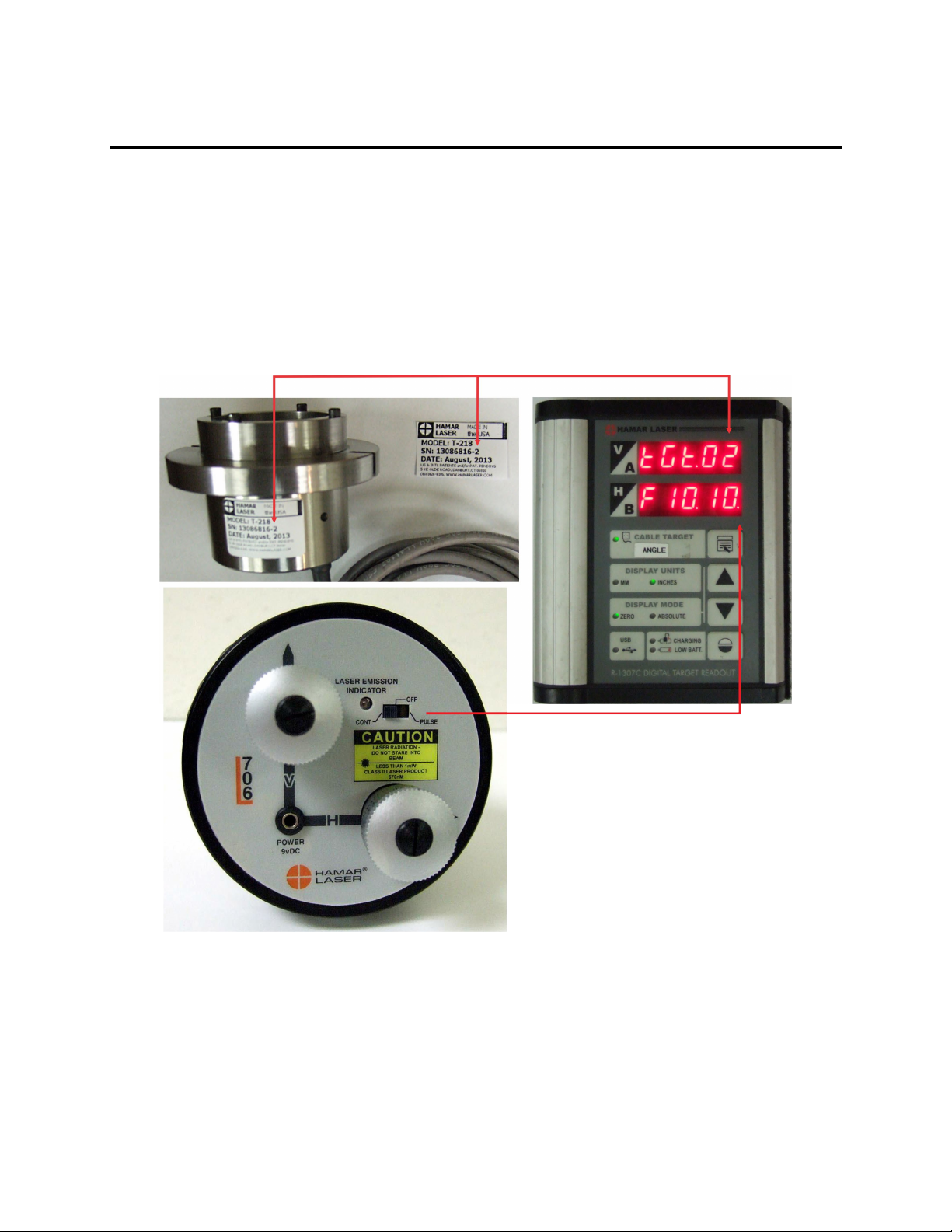
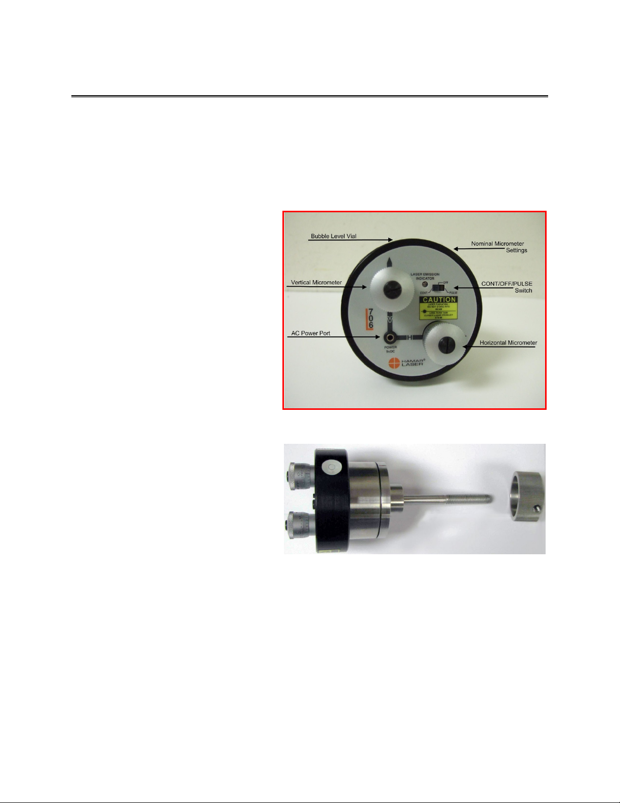
The following describes the operational features of the laser. These features include bubble level vial
orientation, micrometer values and settings, ON/OFF switches and the external battery pack.
•The ON/OFF slide switch has a lighted LED to indicate that power is ON.
•The Pulse/Continuous switch selects the laser mode compatible with the readout/interface being
used (see Page 4 for more information about Pulse/Continuous modes and the readouts used for each
mode).
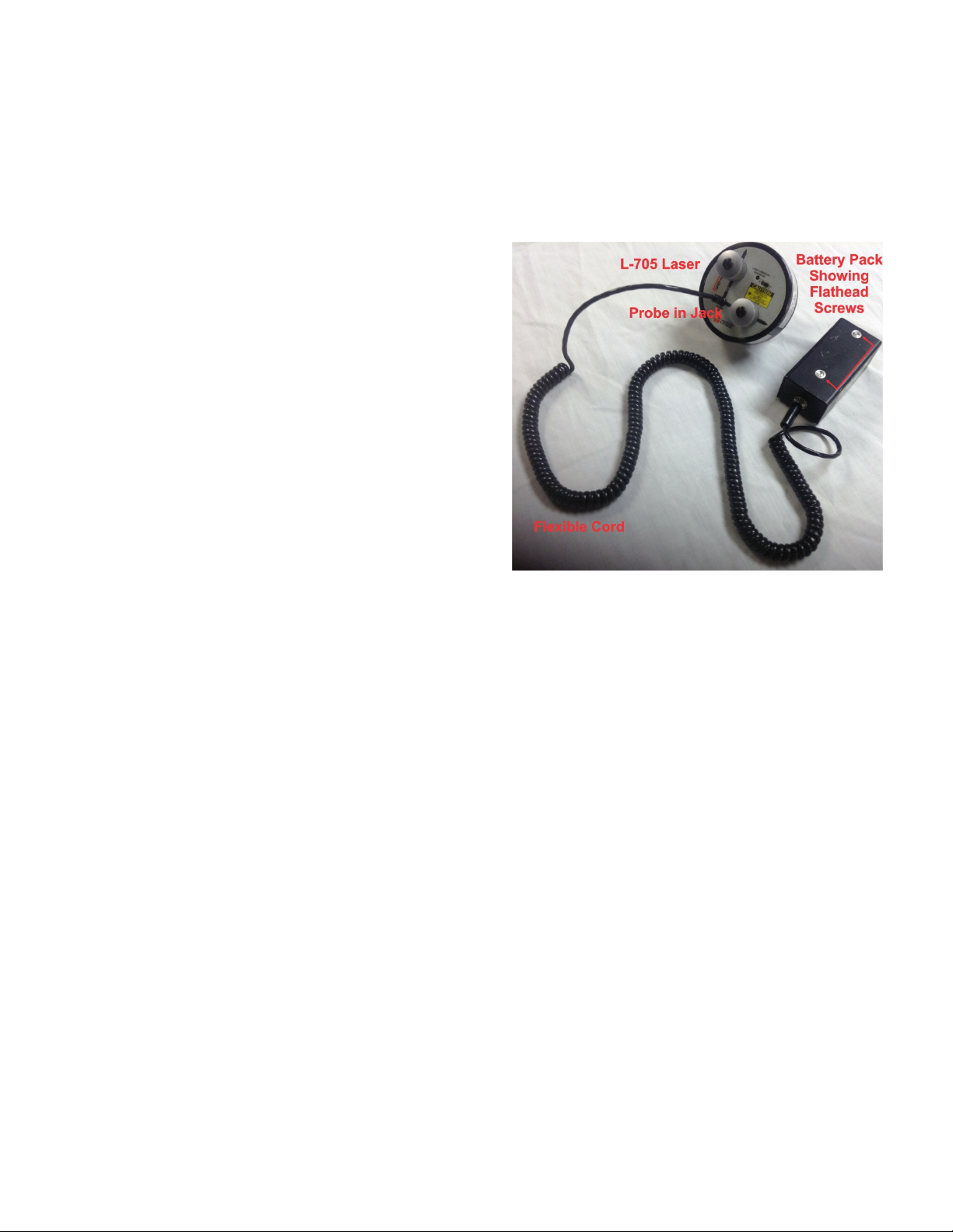
•Battery Pack connector accepts a slip-fit probe with a flexible cord.
•Bubble level vials on the laser mounting flange are used for rotational accuracy. When the bubbles
in the level vial are centered horizontally, all micrometer adjustments (controlling laser beam angle)
will shift the laser beam vertically or horizontally with reference to the bore/target axis. If the
bubbles are not centered, any micrometer adjustment to one laser axis will change the laser beam
position in both axes. The levels also provide fixture mounting repeatability (assuming the laser is
hard-mounted to fixture).
•Micrometer controls are provided for the adjustment of the angle at which the laser beam emerges
from the precision ground, mutually concentric steel laser housing. Each laser has a NOMINAL
setting for both the V-Vertical and the H-Horizontal micrometer controls. The nominal settings are
determined at the factory and correlate to values for the laser beam when it is perpendicular to both
the 2 in. and 4 in. mounting faces. When the bubble in one of the level vials is centered, a nominal
setting of each micrometer squares the laser beam to that specific axis. For example, if the nominal
vertical setting is .120, then setting the micrometer to .120 sets the laser beam square to the vertical
axis. When a laser is mounted in the gearbox or bore adapter, vertical and horizontal micrometers
should be set in the nominal positions to facilitate the alignment and measurement process.
Adjusting the Laser
The laser beam is factory-adjusted to be concentric to the
mounting diameters (2.25 in. or 57.15 mm and .75 in. or 19.05
mm) within ±.0005 in. (0.0127 mm). With the adjusting
micrometers set at the nominal position, (see the Nominal
Settings label on the outer flange), the laser beam is perpen-
dicular to the front mounting surface and parallel to the
mounting diameters within ±.0003 in/ft.
In a typical bore measuring application, the laser is mounted
concentric to one end of the bore by means of a fixture ring or
plate. Because fixtures are seldom perfect, the laser beam
requires angular adjustment to make it concentric to the bore.
This is accomplished by placing the Self-Centering measuring
target at the other end of the bore and adjusting the mi-
crometers on the laser until the laser beam is centered on the
target.
The circular level vial on the laser mounting flange is used to
reference the orientation of the vertical and horizontal axes of
the laser. When the bubble in the level vial is centered, all
Figure 2–Laser Micrometer Adjustments