HAMAR LASER T-212 User manual


WARRANTY
Hamar Laser Instruments, Inc., warrants each instrument and other articles of
equipment manufactured by it to be free from defects in materials and
workmanship under normal use and service, its obligation under this warranty
being limited to making good at its factory any instrument and other article of
equipment which shall within one year after shipment of each instrument and
other article of equipment to the original purchaser be returned intact to Hamar
with transportation prepaid, and which Hamar’s examination shall disclose to
Hamar’s satisfaction to have been thus defective; other than this express
warranty, Hamar neither assumes nor authorizes any other persons to assume for
it any other liability or obligation in connection with the sale of its products.
This warranty is not applicable to instruments or other articles of equipment
manufactured by other companies and limited by a warranty extending for less
than one year. In such an event, the more limited warranty applies to said
instrument or article of equipment.
This warranty shall not apply to any instrument or other article of equipment
which shall have been repaired or altered outside the Hamar factory, nor which
has been subject to misuse, negligence, or use not in accord with instructions
furnished by the manufacturer.
The software described in this manual is furnished under a license agreement and
may be used or copied only in accordance with the terms of the agreement. It is
against the law to copy the software on any medium for any purpose other than
the purchaser's personal use.
The information in this manual is subject to change without notice. No part of
this manual may be reproduced by any means, electronic or mechanical, without
written permission from Hamar Laser Instruments, Inc.
© Copyright Hamar Laser Instruments, Incorporated, 2019
5 Ye Olde Road, Danbury, Connecticut 06810

Table of Contents
Introducing the T-212 4-Axis Target...............................................................................................1
Interpreting Signs .........................................................................................................................2
How the T-212 Target Measures Angle.......................................................................................3
How the T-212 Target Measures Center ......................................................................................3
The Index Module ........................................................................................................................3
Mounting Error Calculation .......................................................Error! Bookmark not defined.

1
Introducing the T-212 4-Axis Target
The T-212 Target is a 4-axis target that measures:
•Vertical and Horizontal center
•Vertical (pitch) and horizontal (yaw) angle
The target works in two modes; Centering and Angular.
•Centering Mode detects vertical and horizontal
displacement or movement. The resolution is .0001
in. (0.001 mm) using the R-1307, or .00001 in.
(0.00025 mm) using the R-358 Computer Interface
•Angular Mode detects an angular (pitch and yaw)
displacement or movement. The resolution using the
R-1307 Readout is .0001 in/in (0.001 mm/25.4mm) or
.00001 in/in. (0.00025 mm/25.4 mm) using the R-358
Computer Interface.
Only one mode may be used at a time. To operate the target in Centering Mode, a small light shield is
inserted in the front of the target (see Figure 2).
Figure 2 – Centering and Angular Modes
To switch to Angular Mode, remove the light shield and insert the
lens module using the index pin (see Figure 3) to orient the lens
properly. Rotate the module until the index pin is located opposite
the slot in the body of the target, then slide the reference pin into
the slot. The readings displayed in the Readout are converted to
in/in. For example, when inserting the lens, .0023 displays on the
V-axis of the readout. This means the target is tilting down by
.0023 in/in. A minus (-) V-axis reading means the target is
pointing up (see Interpreting Signs on Page 2).
For the H axis, a + reading means the target is pointing to the left
(front of the target is to the left of the back) when looking down
on top and in front of the target. A “-“ H-axis reading means the
target is pointing to the right (see Interpreting Signs on Page 2 ).
Figure 3 – Reference Pin
Figure 1 – T-212 4-Axis Target

2
Level vials are used on the top and bottom of the T-212 to perform the NORMIN procedure (see The
NORMIN Procedure on Page 5).
The T-212 Target's half-inch mounting stud is designed for use with Hamar Laser's target mounting
fixtures. Custom mounting fixtures are simple to design—a ½ in. hole reamed square to a face is all that is
required to hold the target.
Interpreting Target Data Signs (+, -)
T-212 Target Angular Axes
T-212 Target Center Axes

3
How the T-212 Target Measures Angle
Figure 4 shows how the T-212 Target measures angle. It uses a lens that has a 1-inch focal length, which
means any deviations detected by the PSD sensor are expressed in inches/inch (mm/25.4 mm). To
understand this better, imagine that there is another PSD sensor 1 inch behind the where the T-212’s PSD
is actually located. So any angular changes in the target will produce different readings for the PSD in
the actual location versus the reading in the “virtual” location.
For example, if the readout shows a vertical reading of .001 in. in angular mode, this indicates the laser
beam is located on the virtual PSD a .001in. higher than its location on the actual PSD.
Another way to think about is it’s a lot like using a dial indicator to take a measurement for center in one
location along on a bar (or bore) and moving along the bar (or down the bore) and taking a second
measurement. When the second measurement is subtracted from the first, the results shows the pitch and
yaw of the axis of the bar (or bore) relative to the mechanical axis used to support the indicator.
Figure 4 – Measuring Angle with the T-212 Target
With the T-212, this “subtraction” is accomplished automatically using an optical lens, so the user can
view the angular pitch and yaw of the axis of the target relative to the axis of the laser beam on the
readout without performing any calculations. The axis of the laser beam represents where the target ought
to be, the axis of the target represents where is actually is, and the difference between the two displays on
the readout.
How the T-212 Target Measures Center
With the lens module removed, the target operates in Centering Mode. After the lens module is removed,
insert the light shield in its place. There is no particular orientation for the light shield.
In Centering Mode, the target is sensitive to vertical and horizontal displacement. The target is sensing at
the plane of the cell and the readout displays the position of the target relative to the laser beam if the
target is high or low and left or right relative to the laser beam).
Figure 5 – T-212 with Light Shield in Center Mode

4
The Index Module
There is a removable index module (see Figure 5) mounted on the target
to aid in the indexing of the target at 0 and 180 degrees. The procedure
of indexing the target at 0 and 180 degrees is done when the target is
used to check the alignment of an axis of rotation and the alignment of a
bore. The module can be loosened and positioned in any orientation or
removed from the target when it is not needed.
To use the Index Module, rotate the target so that the bubble level is
showing “level,” then take a reading. Rotate the target 180 degrees, re-
level the target and take a reading.
Mounting Error Calculation
All T-212 targets are shipped with the target PSD aligned to the housing within .0005 in. TIR. In time,
handling may cause the target cell to become out of center. To remove centering and fixture errors, use
the NORMIN method of taking a normal reading, rotating the target 180 degrees and taking another
reading, and splitting the difference between the two (see The NORMIN Procedure beginning on Page 5).
This is done for the center values and angular values separately.
Figure 6 – T-212 with Index Module

5
Appendix A - The NORMIN Procedure
The NORMIN method was
developed by Hamar Laser
Instruments as a way of
compensating for laser or target
mounting errors in bore or spindle
work. The word is a contraction of
“NORMal-INverted,” which briefly
describes the method. It is quite
similar to the four clock readings
taken with dial indicators but uses a
laser and a target instead. The
NORMIN method is used in
conjunction with simple fixtures and
targets that allow inexpensive,
precision measurement. The
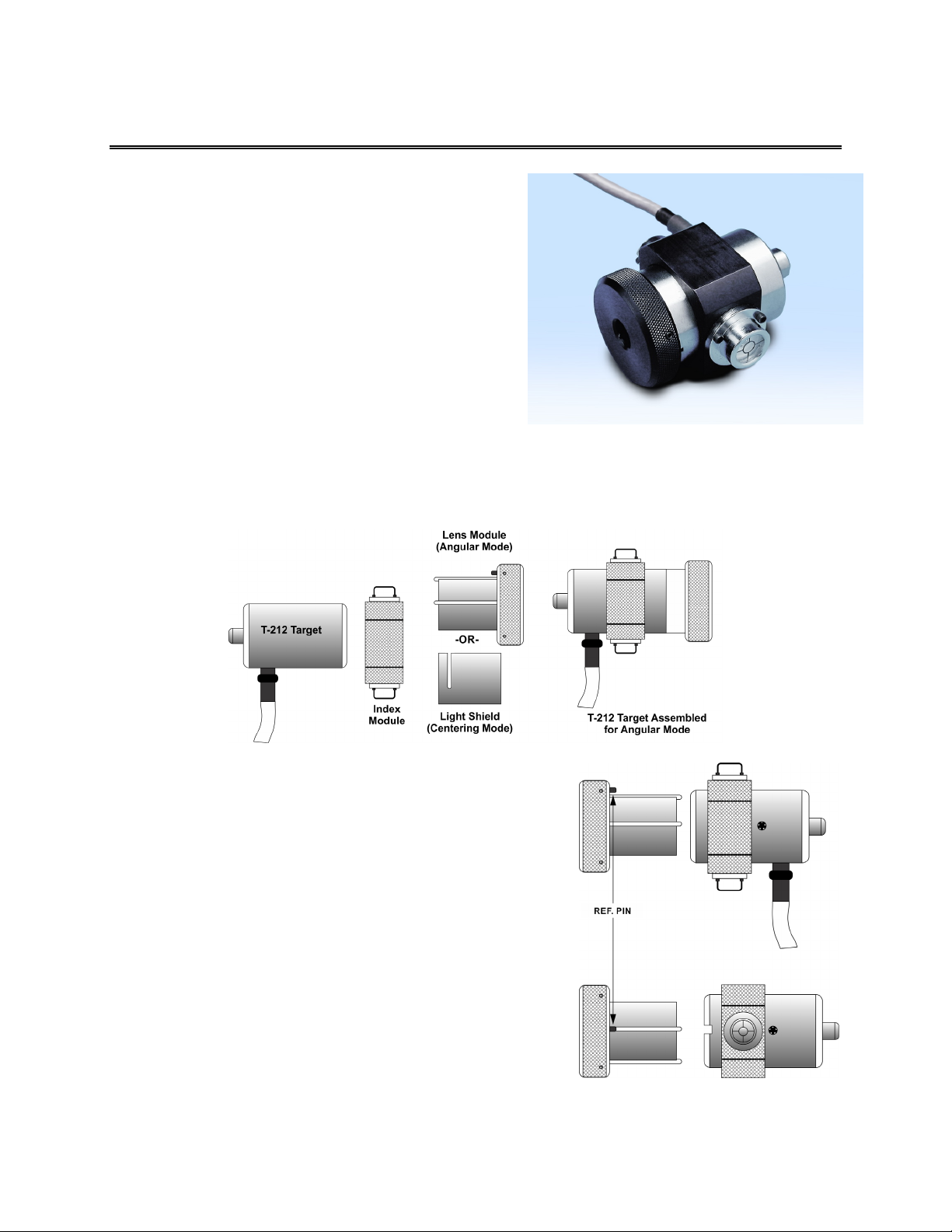
target/fixture is set in the bore or
spindle in the NORMal position
(cable down) and the readings are
recorded. Then the target/fixture is
rotated 180 degrees to the INverted
(cable up) position, and a second set
of readings is obtained. The two sets
of readings cancel out centering
errors and provide a very accurate
result.
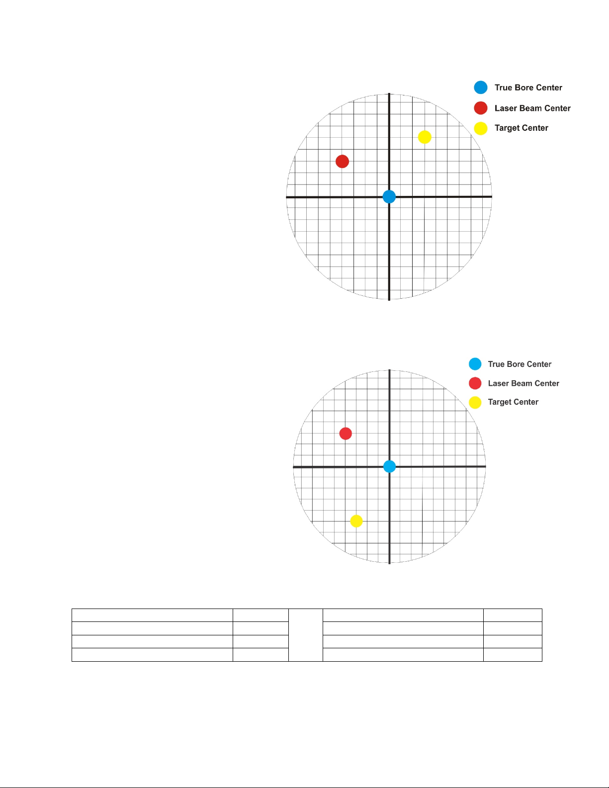
There are three centers involved in
bore alignments: True Bore Center,
Target Center, and Laser Reference
Centerline. If mounting fixtures
were perfect, the Target Center would be located at the True Bore Center, and if perfectly aligned, the
True Bore Center would be located at the laser beam center. In reality, however, they seldom line up. An
example of the three centers with respect to one another is shown in Figure 7.
Two relationships can be calculated from these three centers and two sets of NORMIN readings: Target
Sensor Concentricity Error (TSCE) and the True Bore Misalignment (TBM). The True Bore
Misalignment (TBM) is used when it is desirable to know the true bore centerline position relative to the
laser beam center without fixture errors. Usually, the laser beam center is where a bore center should be
located, and the TBM shows its actual location. The Target Sensor Concentricity Error (TSCE) is used if
the operator wants to place the laser beam center exactly in the middle of a bore.
The general rule is: buck in to the TSCE and measure the TBM.
Figure 5 -- Three centers of bore alignment

6
The readout always shows the displacement
between the Target Center and the Laser Beam
Center. When the Target Center is not on the
True Bore Center, the numbers and the signs
on the readout will change when the target is
rotated because the Target Center is moved to
a different location in relationship to the laser
beam.
Figure 8 represents the target in the NORMal
position, with the cable down. If each square
represents .001 in., the Target Center is .002
in. higher than the Laser Beam Center (+.002
in.) and is .007 in. to the right of the Laser
Beam Center (+.007 in.).
Figure 6 – Target in the NORMal position
Figure 9 represents the target in the INverted
position, with the cable up. When the target is
rotated, the signs on the readout are also rotated.
Therefore, although the Target Center appears
to be to the right of and lower than the Laser
Beam Center in Figure 9, the vertical readings
are positive, and the horizontal readings are
negative. When the vertical TCE is calculated,
(NORMal+INverted divided by 2) the Target
Center is .004 in. higher and .003 in. to the right
of the True Bore Center in the NORMal
position.
The table below shows the calculation of the
vertical and horizontal TSCE values.
Figure 7 – Target in the INverted position
NORMal Vertical Reading
+.002 in.
NORMal Horizontal Reading
+.007 in.
INverted Vertical Reading
+.008 in.
INverted Horizontal Reading
-.001 in.
Total
+.010 in.
Total
+.006 in.
Divide by 2 = Vertical TSCE
+.005 in.
Divide by 2 = Horizontal TSCE
+.003 in.
If you place the Laser Beam Center exactly on the True Bore Center with the target in the NORMal
position, the readings will show Vertical +.005 in. and Horizontal +.003 in.
Table of contents
Other HAMAR LASER Industrial Equipment manuals
Popular Industrial Equipment manuals by other brands

ASCO Numatics
ASCO Numatics 453 Installation and maintenance instructions

Genmitsu
Genmitsu PROVerXL 4030 V2 user manual

Renishaw
Renishaw OMP40-2 manual

BONFIGLIOLI
BONFIGLIOLI HDP Series Installation use and service manual

SMC Networks
SMC Networks MGQ Series Operation manual

TKS
TKS FeedBelt - Lite Operator's manual

Extreme Networks
Extreme Networks PowerDrive Orbit Quick operation guide

Curtiss-Wright
Curtiss-Wright POP-A-PLUG SYSTEM operating instructions

Aerotech
Aerotech PRO225LM Series Hardware manual

Weidmann
Weidmann MV5 operating instructions

MM
MM ECO PICK-UP 500L Installation and safety manual

Global
Global WF 9995-AE Instructions & operating manual