manuals.online logo
Brands
  1. Home
  2. •
  3. Brands
  4. •
  5. Hamilton Beach
  6. •
  7. Blender
  8. •
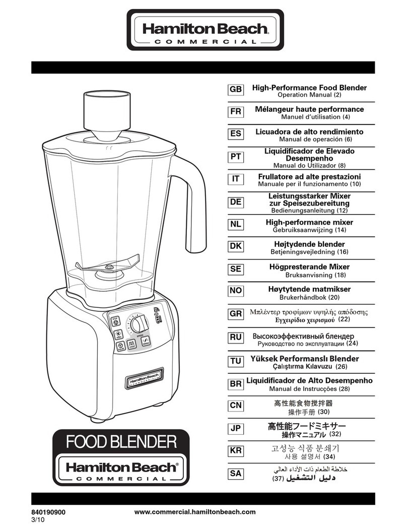
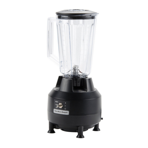
  9. Hamilton Beach HBH550 Instruction Manual

Hamilton Beach HBH550 Instruction Manual

Technical Data Sheet
HBH550 –220-240V
PROPRIETARY RIGHTS NOTICE This document and all information contained within it is the property of Hamilton Beach Brands, Inc. (HBB). It is confidential and
proprietary and has been provided to you for a limited purpose. It must be returned or destroyed upon request. Disclosure, reproduction or use of this document and
any information contained within it, in full or in part, for any purpose is forbidden without the prior written consent of HBB. No photographs may be taken of any article
fabricated or assembled from this document without the prior written consent of HBB.
4421 Waterfront Drive
Glen Allen, VA 23060
Revision Description:
Corrected for clarification
Request Number:
DOC4244
Revision Date:
11/7/13
Approved by:
DOC4244
Issue Code(s):
L
Page:
1of 8
Document #:
520006901
Rev:
C
ENG-FRM-RIC-4.32, Rev. E
Trouble Shooting Guide
- Symptom: During a normal cycle the machine has stopped.
- Cause: The unit has possibly overheated. Check the electrical circuit. Check the reset
switch. If both check OK, unplug the machine and allow it to cool for 15-30 minutes.
Plug it back in and try running the machine.
- Symptom: No response when the start switch is activated.
- Cause: Ensure the power outlet is operational. Ensure that the circuit breaker on the
bottom of the machine is in the on position.
- Symptom: Start/On Stop switch is binding.
- Cause: Ensure switch is free of debris. Gently clean around edges.
- Symptom: High/Low/Pulse switch is binding.
- Cause: Ensure switch is free of debris. Gently clean around edges.
- Symptom: Timer control knob is binding.
- Cause: Ensure there is no debris behind timer control knob. Pull straight back on knob.
Clean any debris from back of knob.
- Symptom: Timer Control knob fails.
- Cause: Possible loose connection between control board and timer control board.
Possible timer control board failure. Possible control board failure. Refer to repair guide.
- Symptom: Blender is tripping circuit breaker at wall panel.
- Cause: Unit needs a dedicated 15 amp circuit (no additional electrical devises should
be operating on this circuit). If unit is tripping circuit breaker while operating on a
dedicated circuit the cause could be a short on the control board.
- Symptom: LED light comes on but the machine will not start.
- Cause: The most probable cause is control board failure. Refer to repair guide.
- Symptom: Unit is noisy.
- Cause: Cutter assembly on container possibly worn. Drive coupling on blender base
possibly worn. Refer to repair guide.
- Symptom: Unit sounds like it running wide open.
- Cause: Possible RFI Board failure, possible Control Board failure. Refer to Repair
Guide.
Technical Data Sheet
HBH550 –220-240V
PROPRIETARY RIGHTS NOTICE This document and all information contained within it is the property of Hamilton Beach Brands, Inc. (HBB). It is confidential and
proprietary and has been provided to you for a limited purpose. It must be returned or destroyed upon request. Disclosure, reproduction or use of this document and
any information contained within it, in full or in part, for any purpose is forbidden without the prior written consent of HBB. No photographs may be taken of any article
fabricated or assembled from this document without the prior written consent of HBB.
4421 Waterfront Drive
Glen Allen, VA 23060
Revision Description:
Corrected for clarification
Request Number:
DOC4244
Revision Date:
11/7/13
Approved by:
DOC4244
Issue Code(s):
L
Page:
2of 8
Document #:
520006901
Rev:
C
ENG-FRM-RIC-4.32, Rev. E
Repair Guide
Housing Disassembly (See Figure 1.)
- Turn power switch to the off position and unplug the machine for any repair or
parts replacement.
- Remove the jar pad.
- Remove the four screws under jar pad feet.
- Carefully lift the upper housing off and tilt it towards the front of the machine;
movement will be limited by wires.
Figure 1. Machine Interior
Motor Wiring Details
- Black motor lead from the non-thermal control device side of the motor routes to
terminal J3 on the Control Board.
- Black motor lead from the thermal control device side of the motor routes to J4
on the Control Board.
Technical Data Sheet
HBH550 –220-240V
PROPRIETARY RIGHTS NOTICE This document and all information contained within it is the property of Hamilton Beach Brands, Inc. (HBB). It is confidential and
proprietary and has been provided to you for a limited purpose. It must be returned or destroyed upon request. Disclosure, reproduction or use of this document and
any information contained within it, in full or in part, for any purpose is forbidden without the prior written consent of HBB. No photographs may be taken of any article
fabricated or assembled from this document without the prior written consent of HBB.
4421 Waterfront Drive
Glen Allen, VA 23060
Revision Description:
Corrected for clarification
Request Number:
DOC4244
Revision Date:
11/7/13
Approved by:
DOC4244
Issue Code(s):
L
Page:
3of 8
Document #:
520006901
Rev:
C
ENG-FRM-RIC-4.32, Rev. E
Motor Removal and Replacement
- Disassemble upper housing as described in housing disassembly above.
- Disconnect the motor leads from terminals J3 and J4 on the Control Board.
- Remove the two screws securing the lower housing.
- Remove the ground wire from motor chassis.
- Lift the motor from the lower housing.
- Assemble in reverse order.
Cord Socket and Circuit Breaker Wiring Details (See Figure 2.)
- White wire from left terminal of cord socket splits to wire nut and routes to Reset
terminal of circuit breaker/On-Off switch and to J3 on RFI board
- Yellow/Green striped wire routes from center terminal of cord socket to the
motor chassis (ground).
- Red wire routes from the right terminal of the cord socket to the Off terminal of
the circuit breaker.
- Black wire routes from center terminal of circuit breaker to the RFI Board J2
terminal.
Figure 2. Interior View of Power Cord, Socket Cord and Circuit Breaker
Technical Data Sheet
HBH550 –220-240V
PROPRIETARY RIGHTS NOTICE This document and all information contained within it is the property of Hamilton Beach Brands, Inc. (HBB). It is confidential and
proprietary and has been provided to you for a limited purpose. It must be returned or destroyed upon request. Disclosure, reproduction or use of this document and
any information contained within it, in full or in part, for any purpose is forbidden without the prior written consent of HBB. No photographs may be taken of any article
fabricated or assembled from this document without the prior written consent of HBB.
4421 Waterfront Drive
Glen Allen, VA 23060
Revision Description:
Corrected for clarification
Request Number:
DOC4244
Revision Date:
11/7/13
Approved by:
DOC4244
Issue Code(s):
L
Page:
4of 8
Document #:
520006901
Rev:
C
ENG-FRM-RIC-4.32, Rev. E
RFI Filter Wiring Details (See Figure 3.)
- Black wire (top left) J4 from the top left terminal to terminal J1 on the Control
Board.
- Blue wire (bottom left) J5 to terminal J2 on the Control Board.
- White wire (top right) J3 splits to left terminal of cord socket plug and Reset
terminal of circuit breaker/On-Off switch.
- Black wire (center right) J2 to center terminal of circuit breaker.
- Yellow/Green striped wire (bottom right) J1 to motor chassis.
RFI Board Removal and Replacement
- Disconnect wires from RFI board, mark if necessary or refer to wiring detail for
proper placement.
- Remove the three Phillips screws and gently pull the RFI board off blender.
- Replace with new board, and assemble in reverse order.
Figure 3. RFI FILTER
Technical Data Sheet
HBH550 –220-240V
PROPRIETARY RIGHTS NOTICE This document and all information contained within it is the property of Hamilton Beach Brands, Inc. (HBB). It is confidential and
proprietary and has been provided to you for a limited purpose. It must be returned or destroyed upon request. Disclosure, reproduction or use of this document and
any information contained within it, in full or in part, for any purpose is forbidden without the prior written consent of HBB. No photographs may be taken of any article
fabricated or assembled from this document without the prior written consent of HBB.
4421 Waterfront Drive
Glen Allen, VA 23060
Revision Description:
Corrected for clarification
Request Number:
DOC4244
Revision Date:
11/7/13
Approved by:
DOC4244
Issue Code(s):
L
Page:
5of 8
Document #:
520006901
Rev:
C
ENG-FRM-RIC-4.32, Rev. E
Control Board Wiring Details (Figure 4.) Switch Wiring Details (Figure 5.)
- Black wire from the control board J1 terminal connects to the J4 terminal on the
RFI Board.
- Blue wire from control board J2 terminal connects to the J5 terminal on the RFI
Board
- Black motor lead without the thermal device connects to J4 on the control board.
- Black motor lead with thermal control device connects to J3 on the control board.
- Blue wire from the control board OFF terminal connects to the Stop terminal of
the Start/Stop/On switch (top left position).
- White wire from the control board START terminal connects to the Start terminal
on the Start/Stop/On switch (bottom left position).
- Brown wire from the control board PULSE terminal connects to the Pulse terminal
on the High/Low/Pulse switch (top right position).
- Black wire from the control board HIGH terminal connects to the High terminal on
the High/Low/Pulse switch (bottom right position).
- Gray wire from the control board ON terminal connects to the On terminal on the
Start/Stop/On switch (center left position).
- Red wire from the control board LOW terminal connects to the Low terminal on the
High/Low/Pulse switch (center right position).
- Terminal J6 on the control board connects to the 3 pin connector on the Timer
Control Board.
- Terminal J8 on the control board connects to the 3 pin connector on the Jar Sensor.
Control Board Removal and Replacement
- Disconnect wires from control board one at a time and mark if necessary for
proper placement.
- Remove the four screws holding the control board in place.
- Lift the control board from the machine. Place new control board on to lower
housing and replace screws.
Switch Removal and Replacement
- Remove upper housing as described above.
- Disconnect wires from switch terminals. Mark wires if necessary for reference.
- Cut wire ties if necessary.
- Push in and down at each corner of switch retaining bracket.
- Replacement of control panel may be necessary.
- Assemble in reverse order.
Technical Data Sheet
HBH550 –220-240V
PROPRIETARY RIGHTS NOTICE This document and all information contained within it is the property of Hamilton Beach Brands, Inc. (HBB). It is confidential and
proprietary and has been provided to you for a limited purpose. It must be returned or destroyed upon request. Disclosure, reproduction or use of this document and
any information contained within it, in full or in part, for any purpose is forbidden without the prior written consent of HBB. No photographs may be taken of any article
fabricated or assembled from this document without the prior written consent of HBB.
4421 Waterfront Drive
Glen Allen, VA 23060
Revision Description:
Corrected for clarification
Request Number:
DOC4244
Revision Date:
11/7/13
Approved by:
DOC4244
Issue Code(s):
L
Page:
6of 8
Document #:
520006901
Rev:
C
ENG-FRM-RIC-4.32, Rev. E
Figure 4. Front View of Control Board with Motor Removed.
Figure 5. Interior View of Switches, Jar Sensor, and Timer Control Board with
LED and Wires Connected.
Top:
Stop Terminal
(blue wire)
Middle:
On Terminal
(gray wire)
Bottom:
Start Terminal
(white wire)
Top:
Pulse Terminal
(brown wire)
Middle:
Low Terminal
(red wire)
Bottom:
High Terminal
(black wire)
Technical Data Sheet
HBH550 –220-240V
PROPRIETARY RIGHTS NOTICE This document and all information contained within it is the property of Hamilton Beach Brands, Inc. (HBB). It is confidential and
proprietary and has been provided to you for a limited purpose. It must be returned or destroyed upon request. Disclosure, reproduction or use of this document and
any information contained within it, in full or in part, for any purpose is forbidden without the prior written consent of HBB. No photographs may be taken of any article
fabricated or assembled from this document without the prior written consent of HBB.
4421 Waterfront Drive
Glen Allen, VA 23060
Revision Description:
Corrected for clarification
Request Number:
DOC4244
Revision Date:
11/7/13
Approved by:
DOC4244
Issue Code(s):
L
Page:
7of 8
Document #:
520006901
Rev:
C
ENG-FRM-RIC-4.32, Rev. E
Jar Pad Sensor Removal and Replacement
- Disconnect jar pad sensor from J8 terminal of the Control Board.
- Remove any glue or adhesive holding jar pad sensor wire to inside of upper
housing.
- Gently remove jar pad sensor from upper housing using needle nose pliers or a
similar tool.
- Jar pad sensor is keyed to ensure that it inserts correctly into upper housing.
- Reconnect lead wire to J8 terminal of the Control Board and hot glue excess
wire into upper housing wire slot.
Timer Control Knob Removal and Replacement
- Disassemble upper housing as described above.
- Remove timer control knob by gently pulling straight back.
- Remove moisture seal and remove hex nut and washer.
- Timer control board will drop out of upper housing.
- Disconnect wire from timer control board and connect to new timer control
board.
- Assemble in reverse order.
Replacing the Control Panel
- Remove switches, timer control knob, moisture seal, and timer control board.
- Start at one edge and remove slowly from upper housing.
- Remove any adhesive residue using a mild adhesive remover such as Goo
Gone.
- Allow to completely dry and replace with a new control panel.
- Assemble switches, timer control board, moisture seal, and timer control knob in
reverse order.
- Replace wire ties as needed.
Replacing the Drive Coupling
- Turn the unit upside down. Place a 5/16 hex key into the bottom of the motor
drive.
- Grasp the drive coupling at the top of the blender base with non-slip tool and
hold the hex key in place while turning the drive coupling counterclockwise. This
will loosen the drive coupling enough so that it can be removed by hand.
Replace with new drive coupling.
Technical Data Sheet
HBH550 –220-240V
PROPRIETARY RIGHTS NOTICE This document and all information contained within it is the property of Hamilton Beach Brands, Inc. (HBB). It is confidential and
proprietary and has been provided to you for a limited purpose. It must be returned or destroyed upon request. Disclosure, reproduction or use of this document and
any information contained within it, in full or in part, for any purpose is forbidden without the prior written consent of HBB. No photographs may be taken of any article
fabricated or assembled from this document without the prior written consent of HBB.
4421 Waterfront Drive
Glen Allen, VA 23060
Revision Description:
Corrected for clarification
Request Number:
DOC4244
Revision Date:
11/7/13
Approved by:
DOC4244
Issue Code(s):
L
Page:
8of 8
Document #:
520006901
Rev:
C
ENG-FRM-RIC-4.32, Rev. E
Testing the Container for a Worn or Frozen Cutter Assembly
- Remove the container from the blender base. Hold the container by the handle
and slowly turn the coupling at the bottom of the container. The cutter assembly

and drive coupling should turn freely without wobbling or difficulty.
How to Determine Cycle Count
- Turn the power switch to off.
- Unplug the machine.
- Turn the machine upside down so that you can look into grid holes on the
bottom front right.
- Plug the machine in and turn the power switch to the on position.
- Count the number of flashes from the LED lights; first red, then yellow, then
green.
- Example: Red- 2, Yellow- 0, Green- 8. You have recorded 208.
- At the end add two zeros. Your cycle count = 20,800.

Other manuals for HBH550

2

Other Hamilton Beach Blender manuals

Hamilton Beach 840209500 User manual

Hamilton Beach

Hamilton Beach 840209500 User manual

Hamilton Beach HBB908 - Bar Blender, 44 oz. Poly Top User manual

Hamilton Beach

Hamilton Beach HBB908 - Bar Blender, 44 oz. Poly Top User manual

Hamilton Beach 56205 User manual

Hamilton Beach

Hamilton Beach 56205 User manual

Hamilton Beach Bar Blender User manual

Hamilton Beach

Hamilton Beach Bar Blender User manual

Hamilton Beach Tango Series User manual

Hamilton Beach

Hamilton Beach Tango Series User manual

Hamilton Beach HBB250 User manual

Hamilton Beach

Hamilton Beach HBB250 User manual

Hamilton Beach 54220 User manual

Hamilton Beach

Hamilton Beach 54220 User manual

Hamilton Beach DrinkMaster User manual

Hamilton Beach

Hamilton Beach DrinkMaster User manual

Hamilton Beach 51103 User manual

Hamilton Beach

Hamilton Beach 51103 User manual

Hamilton Beach 58146-CL User manual

Hamilton Beach

Hamilton Beach 58146-CL User manual

Hamilton Beach Blender User manual

Hamilton Beach

Hamilton Beach Blender User manual

Hamilton Beach 53601C User manual

Hamilton Beach

Hamilton Beach 53601C User manual

Hamilton Beach HB10 User manual

Hamilton Beach

Hamilton Beach HB10 User manual

Hamilton Beach 840164501 User manual

Hamilton Beach

Hamilton Beach 840164501 User manual

Hamilton Beach 56200T User manual

Hamilton Beach

Hamilton Beach 56200T User manual

Hamilton Beach HBF400 User manual

Hamilton Beach

Hamilton Beach HBF400 User manual

Hamilton Beach 52300 User manual

Hamilton Beach

Hamilton Beach 52300 User manual

Hamilton Beach 2254 User manual

Hamilton Beach

Hamilton Beach 2254 User manual

Hamilton Beach HBH950 Series User manual

Hamilton Beach

Hamilton Beach HBH950 Series User manual

Hamilton Beach Summit Series User manual

Hamilton Beach

Hamilton Beach Summit Series User manual

Hamilton Beach 56206 Owner's manual

Hamilton Beach

Hamilton Beach 56206 Owner's manual

Hamilton Beach 91605 User manual

Hamilton Beach

Hamilton Beach 91605 User manual

Hamilton Beach Blender User manual

Hamilton Beach

Hamilton Beach Blender User manual

Hamilton Beach B91 User manual

Hamilton Beach

Hamilton Beach B91 User manual

Popular Blender manuals by other brands

Scarlett SilverLine SL-1547 instruction manual

Scarlett

Scarlett SilverLine SL-1547 instruction manual

OBH Nordica Elite Mix 7715 manual

OBH Nordica

OBH Nordica Elite Mix 7715 manual

Scotts HEROSHI MARUCHI CHOPPER operating instructions

Scotts

Scotts HEROSHI MARUCHI CHOPPER operating instructions

GE 106644 owner's manual

GE

GE 106644 owner's manual

Braun JB 5050 quick guide

Braun

Braun JB 5050 quick guide

Clas Ohlson 18-4814 manual

Clas Ohlson

Clas Ohlson 18-4814 manual

Braun Multiquick 3 user manual

Braun

Braun Multiquick 3 user manual

Oster 6710 user manual

Oster

Oster 6710 user manual

Cornelius ICE FROST Installation

Cornelius

Cornelius ICE FROST Installation

Sinbo SHB 3149 manual

Sinbo

Sinbo SHB 3149 manual

Braun Multiquick 5 Vario series manual

Braun

Braun Multiquick 5 Vario series manual

BETTY CROCKER BC-1303CK manual

BETTY CROCKER

BETTY CROCKER BC-1303CK manual

Matheo MHB 60 instructions

Matheo

Matheo MHB 60 instructions

AEG STM3 Series Instruction book

AEG

AEG STM3 Series Instruction book

NUTRIBULLET ZNBF30500ZC user guide

NUTRIBULLET

NUTRIBULLET ZNBF30500ZC user guide

Maxwell MW-1160 B Manual instruction

Maxwell

Maxwell MW-1160 B Manual instruction

Smeg BLF01 instruction manual

Smeg

Smeg BLF01 instruction manual

Ninja BLENDER DUO Series Let's get started

Ninja

Ninja BLENDER DUO Series Let's get started

manuals.online logo
manuals.online logoBrands
  • About & Mission
  • Contact us
  • Privacy Policy
  • Terms and Conditions

Copyright 2025 Manuals.Online. All Rights Reserved.