GENERAL
PURPOSE
COMMUNICATIONS
RECEIVER
I
GENERAL
DESCRIPTI'ON
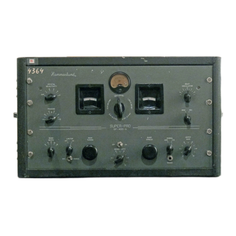
The
SP-600-]X is a20
tube
Radio Communications
Receiver
with
self contained
power
supply.
The]
suffix
in
the
model
number
denotes
that
this
receiver
is made using components
having
characteristics
which
are
the
equivalent
of
military
component
specifications
insofar as is practicable.
The
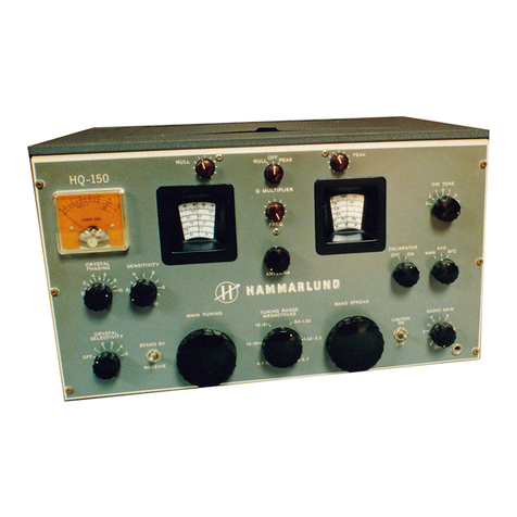
receiver is supplied in
either
awell ventilated·
steel, table model cabinet finished in
dark
grey
to
complement
the
lighter
grey
front
panel
or
for
mount-
ing
in
a
standard
19
inch
relay rack.
The
self contained
power
supply
is
designed
fo~
operation
from asingle phase, 50
to
60 cycle alternat-
ing
current
power
source.
The
power
transformer
primary
is
provided
with
taps covering aline voltage
range
from
90
to
270 volts.
The
power
consumption
is 130 watts.
The
receiver is suitable
for
either
headphone
or
loudspeaker reception
of
AM
radio telephone,
CW
telegraph,
AM
MCW
telegraph signals
and
for
diversity applications.
The
standard
model provides continuous coverage
over
afrequency range from 0.54
to
54.0 megacycles
in
six bands.
The
large easily
operated
band
change
control knob,
on
the
front
panel, selects
the
desired
frequency
band
and
a
band
indicator visible
through
asmall
front
panel
window
indicates
the
frequency
band
in use.
This
control also aligns
the
dial
frequency
indicator
with
the
proper
dial scale.
In
addition to
the
frequency
scales,
the
main dial
has
an
arbitrary
scale
which
in
conjunction
with
the
vernier
dial provides continuous expanded scales
over
each
frequency
band
for extremely accurate logging
and
resetability.
The
single
tuning
control is large
and
of
special
design
to
permit
maximum traverse speed as well as
exceptional
operating
ease.
It
controls
both
the
main
and
vernier
dials.
An
anti-backlash
gear
train
provides
extremely close calibration accuracy
and
completely
accurate resetability. A
tuning
lock provides positive
locking action
without
affecting
the
frequency setting.
The
tuning
ratio from
the
tuning
control
to
the
main dial is 50
to
1
and
the
ratio from
the
vernier
dial
to
the
main dial is 6
to
1.
Two
stages
of
radio
frequency
amplification are
provided
on
all bands. Single conversion is used
for
signal frequencies
up
to
7.4 mc
and
double conversion,
employing acrystal controlled oscillator,
for
signal
frequencies above 7.4 me.
Four
stages
of
IF
amplifica-
tion, detector
and
A
VC
rectifier, noise limiter
and
.
meter
rectifier,
beat
frequency oscillator
and
buffer
[ 5 ]
amplifier,
IF
output,
AF
amplifier
and
output
power
stage
are
provided.
The
frequency
control
unit
provides
for
fixed
channel
crystal controlled operation
on
any
six fre-
quencies
within
the
range
from .75
to
54 mc.
Front
panel.
control~
permit
the
selection
of
the
normal
high
stabIhty contInuously variable
tuning
or
either
of
the
six selected fixed frequency signals.
For
crystal con-
trolled fixed channel
operation
it
is
only
necessary
to
set
the
dial
to
the
signal frequency, switch
to
the
crystal
frequency
desired
and
tune
with
the
delta
frequency cor:trol.
These
crystals are
not
supplied
WIth
the
receIver,
but
may be purchased
on
special
order
from
HAMMARLUND
MFG.
CO.
specifying
the
signal
frequency
for
which
each is
to
function.
The
noise limiter circuit effectively limits
the
inter-
ference from ignition systems
or
other
sources
of
pulse
type
noise.
The
limiter switch
permits
optional use
of
the
limiter.
The
antenna
input
circuit is designed for use
with
abalanced line.
The
input
impedance is nominally
95
ohms.
The
receiver may also be operated
with
a
conventional single
wire
antenna.
The
audio
output
circuit is designed
for
a600
ohm
load
or
line
and
is
provided
with
a
four
terminal split
WIndIng
for
balanced load operation.
Maximum
power
output
is approximately 2.0 watts.
The
headphone
circuit
when
referred
to
an 8000
ohm
load provides
signals
attenuated
approximately
15
db
below
the
600
ohm
power
output.
The
send receive switch desensitizes
the
receiver
b.ut leaves
the
power
on
to
provide
for
instant
recep-
tIOn
between
transmission periods.
Radiation is negligible
and
complies
with
require-
ments
for
shipboard
operation
and
for
multi-receiver
installations.
Frequency
drift
after
a
15
minute
warm
up
period,
ranges
between
.001
percent
and
.01 percent
of
fre-
quency
depending
on
the
frequency used.
This
is a
very
unusual
degree
of
frequency
stability for variable
tuned
HF
oscillators
and
closely approaches crystal
stability.
The
selectivity control provides
three
degrees
of
crystal
and
three
degrees
of
non-crystal selectivity
ranging
from
sharp
(.2 kc)
to
broad
(13.0 kc).
The
crystal filter embodies
the
same circuit features
that
have
proved
so
effective
and
desirable in
Hammar/und
Super
Pro
Receivers,
incorporated
in
an
improved
mechanical
design
.

