Hammerhead 650RS User manual


2
Table of Contents
1 Page 3
2 Page 3
3 Page 4
Page 4
Page 5
Page 5
Page 6
4 Page 6
Page 7
Page 7
Page 9
Page 8
5 Page 9
Page 10
6 Page 10
Page 11
Page 11
Page 12
Page 12
Page 13
7 Page 13
Page 13
Page 13
Page 14
Page 14
8 Page 15
Page 15
Page 15
Page 15
Page 16
9 Page 16
10 Page 17
11 Page 18
Page 18
Page 19
Page 20
Page 20
Page 21
Page 23
12 Page 23
Page 23
Page 24
Page 24
13 Page 25
Page 26
14 Page 27
15 Page 27
16 Page 28
17
Warnings
General Information
Maintenance Intervals
3.1 System Maintenance K (Customer)
3.2 System Maintenance I (125 hours of operation) 3.3
System Maintenance II (250 hours of operation) 3.4
Hammerhead System Maintenance S
(500 hrs of operation, at least yearly)
Squeegee Cable and Recovery Tank Gasket
4.1 Squeegee Adjustment (First Version)
4.2 Squeegee Adjustment (new Style)
4.3 Squeegee Lift Cable, Micro Switch, Vacuum Motor
4.4 Squeegee Wheel Adjustment
Brush Head (Disk Brushes) Connections
5.1 Brush Motor Information
Brush Head Transport Position
6.1 Brush Switch
6.2 Brush Pressure Adjustment on the Disk Models
6.3 Brush Pressure (Disk Decks)
6.4 Cylindrical Brush Head Electrical Connections
6.5 Cylindrical Brush Head Adjustment
Drive and Wheels - General Data
7.1 Electric Brake
7.2 Transaxle Motor
7.3 Carbon Brushes
7.4 Drive Potentiometer
Water Supply
8.1 Solenoid
8.2 Solution Filter
8.4 Solution Flow Rates
8.5 Water Pump
The Last Error
Table of Error Codes and Information
Battery Charger
11.1 Operating Instructions
11.2 Charger Error Codes
11.3 Charger Trouble Shooting
11.4 Charger Maintenance Points
11.5 Programming The Charger
11.6 Replacing The Charger Harness
Batteries
12.1 Maintaining Wet Lead Acid Batteries
12.2 Load Testing Batteries
12.3 Hydrometer Testing
Fuse Locations Version 2
13.1 Controller Version 3
Controller Connections
Trouble Shooting Controller
Contactor Harness
Contactor Wiring Page 29
Page 6
HAMMERHEAD
3
1. Warnings
Disconnect the A.C. Cord from the outlet and and D.C. Cord from the battery
pack before servicing the machine. Except for making voltage and current
measurements.
Before replacing the main fuses, only loosen the nuts. Do not remove them
completely. Failure to do so could cause a short circuit.
Place the new stripe fuse fully and evenly under the nuts and washers and
make sure not to twist the end tabs, they can easily be torn.
After any repair work is done, test the machine for proper operation.
When servicing the machine always observe the general safety and accident
prevention guidlines.
The display offers a service indication. Upon turning on the key switch, a four digit
number describing the software version (e.g. 1.0.0.2) appears for about 3 seconds,
followed by another 4-digit code indicating the last error recorded, then followed by
the hour meter.
If a failure occurs, the code appears in the control panel and an acoustic signal
sounds. The current error code appears as 4-digit alpha-numerical code with
flashing dots in the service display. Only if these criteria are met, the error is a
current one!
The error codes are listed in a tables in chapter 10.
2. General Information
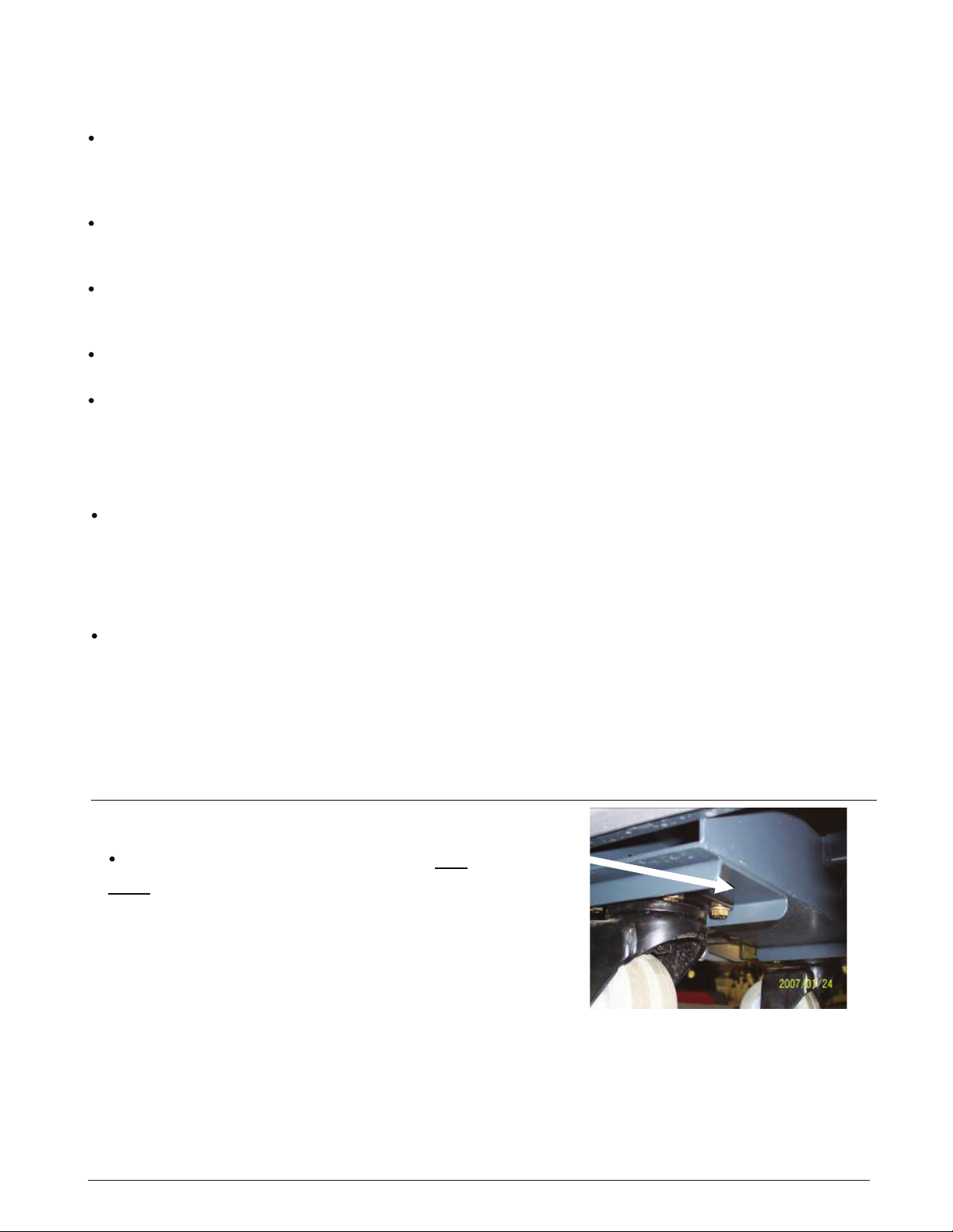
When raising the machine with a car
jack,use the area of the frame in front of
the caster wheels on the left or the right.

4
3. Maintenance Intervals
In a modular structure, the System Maintenance determines the specific technical
proceedures to be preformed and sets the time interval between the two maintenance
cycles.For each of the maintenance cycle, the replaceable parts are determined as well.
Further details described in the specific chapters.
System Maintenance K:
To be performed by the customer (in daily or weekly intervals) according to the maintenance
and care instructions as specified in the operating instructions.
The operator must be professionally instructed after delivery of the machine by selling
dealer.
System Maintenance I: (after every 125 hours of operation)
To be preformed by an authorized Service Center in accordance with the machine-specific
system maintenance.
System Maintenance II: (after every 250 hours of operation)
To be preformed by an authorized Service Center in accordance with the machine-specific
system maintenance.
System Maintenance S: (after every 500 hours of operation, safety check) To be
performed by an authorized Service Center in accordance with the machine-specific system
maintenance.
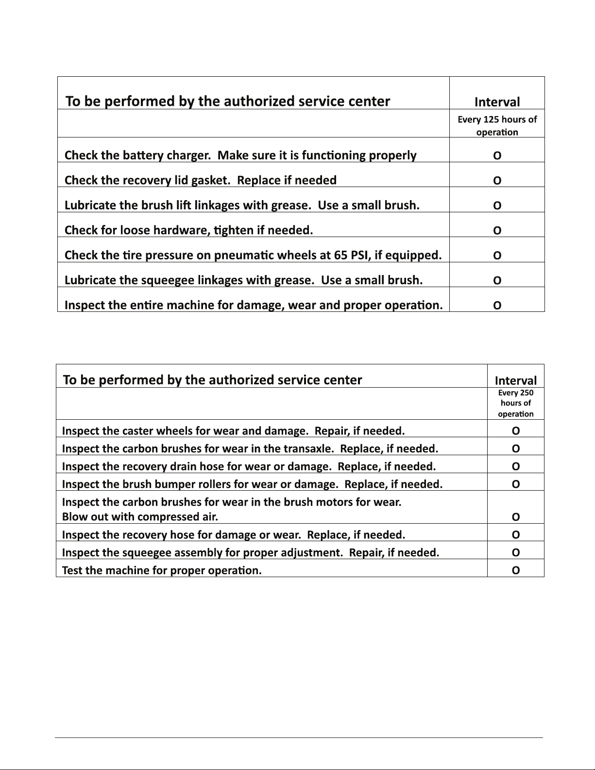
3.1 System Maintenance K
5
3.2 System Maintenance I
3.3 System Maintenance II
6
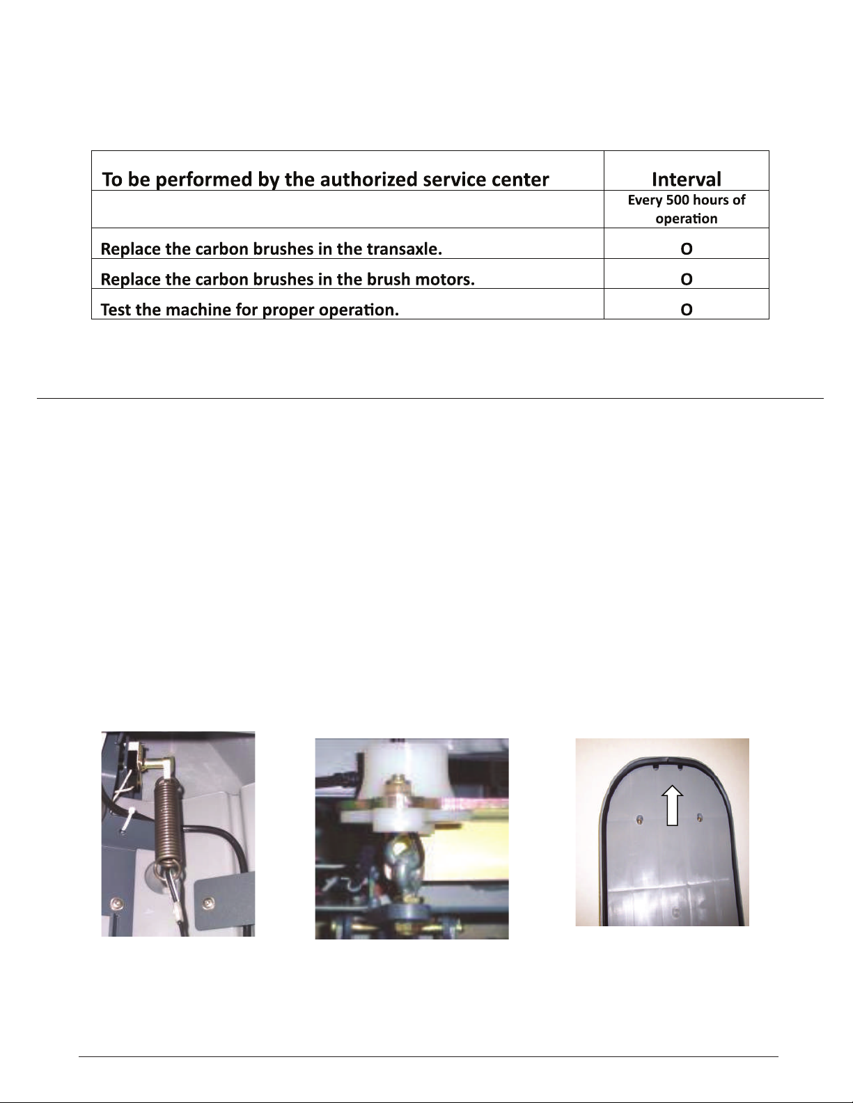
3.4 System Maintenance S
(Safety Check)
4. Squeegee Cable And Gasket
4. The squeegee cable is attached to the lift lever (top) via a spring (Fig. 5/5). The bottom is
attached to the eyebolt at the squeegee mechanism (Fig. 5/6). The squeegee lift cable can be
accessed after opening the electronic module cover at the rear of the machine.
The vacuum motor is connected to the A1 at A1.X34:5+6 on the controller. Current
consumption of the vacuum motor amounts to approx. 25A max.
The vacuum water lift in the closed tank is at least 65 inches (150mbar).
Recovery Lid Gasket
Insert the recovery tank cover gasket (Fig. 5/7) so that the seam is positioned at the front center
with a gap of approx. 1mm. The dirty drip water on the top sealing surface will be drawn into the
recovery water tank.
Fig. 5/5 Fig. 5/6 Fig. 5/7
7
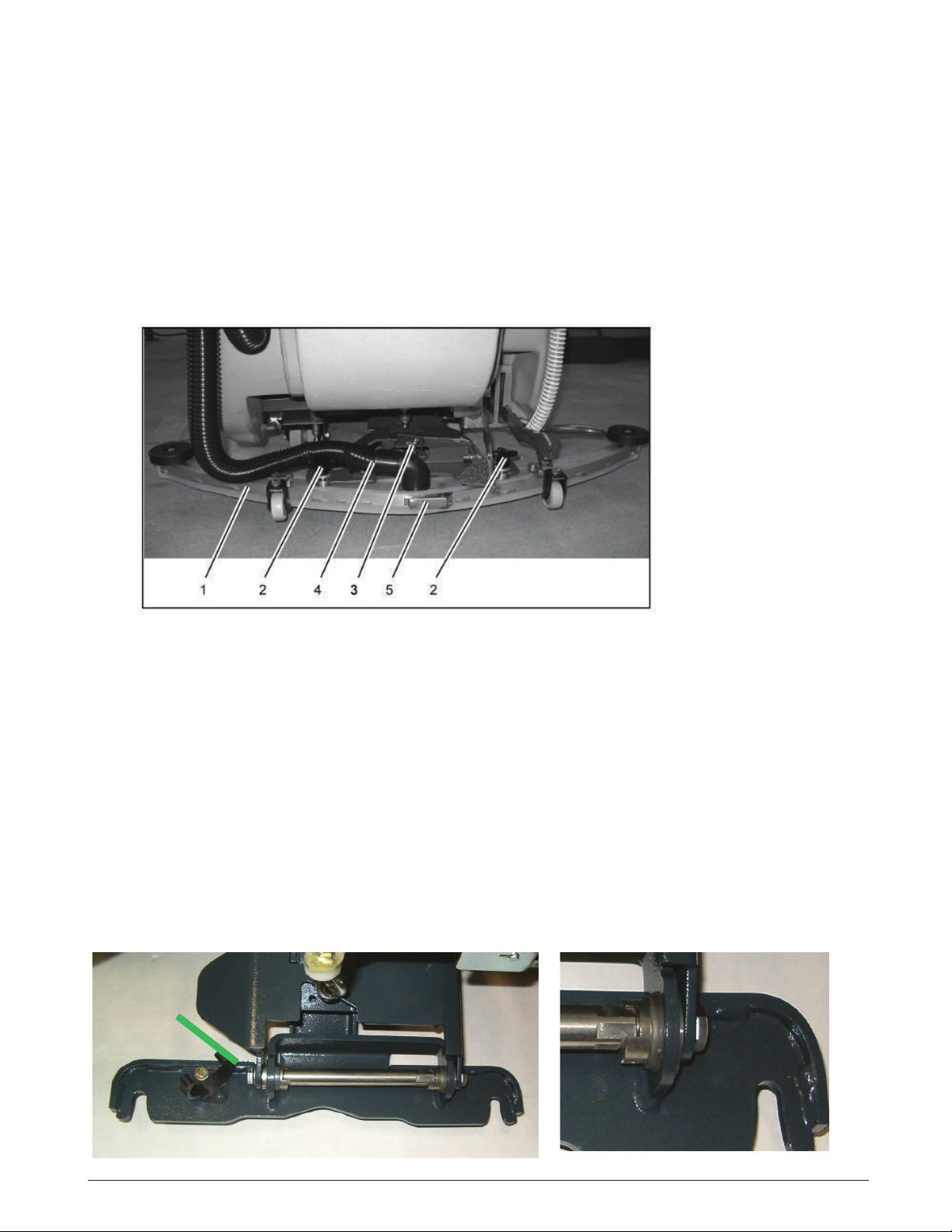
4.1 Squeegee Adjustment
Correct squeegee adjustment is prerequisite for optimal suction results.
Before adjustment first check the pitch of the squeegee and re-adjust if required.
1. Place machine on level ground.
2. Loosen nut of the adjustment screw (pos. 3, Fig. 5/1) and adjust sealing strips in
parallel to the floor. Turn adjustment screw clockwise: clearance between squeegee
blade and floor broadens in the center. Turn adjustment screw counter-clockwise:
clearance between squeegee blade and floor narrows in the center.
3. Turn machine on, lower squeegee and check drying pattern.
1 Squeegee
2 Star-shaped knob
3 Adjustment screw
4 Suction hose
5 Toggle-type fastener
Fig. 5/1
-----Version one
4.2 Squeegee Adjustment-----Version Two
Correct squeegee adjustment is prerequisite for optimal suction results.
Before adjustment first check the pitch of the squeegee and re-adjust if required.
1. Place machine on level ground.
2. Loosen the two bolts, located on each side (Fig 5/2A) with the squeegee attached
while holding another wrench on the location shown on Fig 5/2B. Adjust squeegee
rubbers so that they are parallel to the floor, by turning the long adjustment shaft on the
right side with an open end or adjustable wrench (Fig 5/2B). Adjust until the rear
squeegee blade folds equally accross the entire length, while moving the machine
slightly forward.
3. Tighten the two bolts on the ends while holding the center shaft with the wrench.
4. Turn machine on, lower squeegee and check drying pattern.
Fig 5/2BFig 5/2A
8
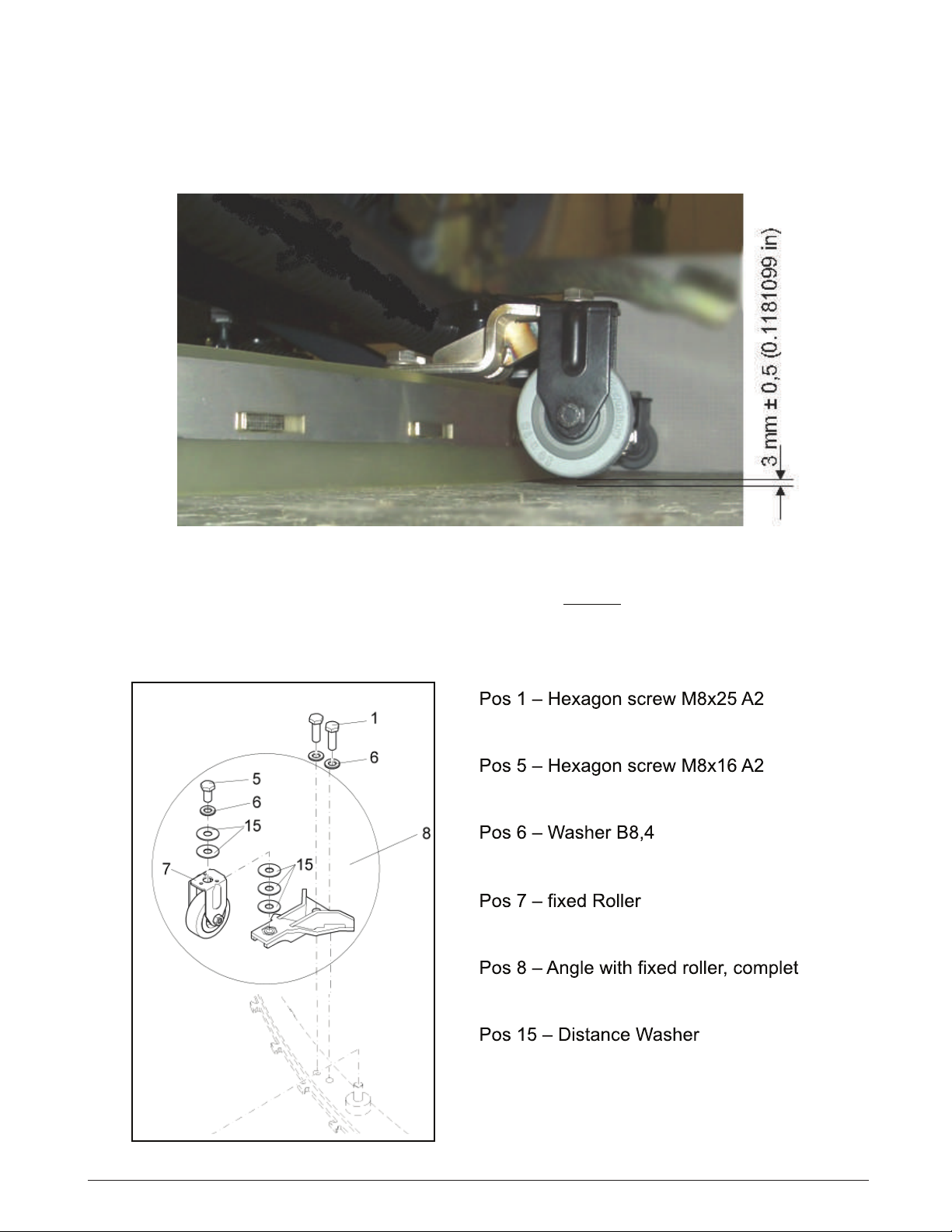
4.3 The clearance between the support roller and floor with squeegee unfolded
(Factory setting) is: 0.1181099 Inches ± 0.01968498 inches (3 mm ±0.5).
Note: Some floor surfaces may require adjusting the caster washers for optimum performance.
4.3 Squeegee Wheel Adjustment
Fig. 5/3
PN 01059530
PN 01071740
PN 00101550
PN 01077810
PN 01079070
PN 01079080
4.4 Note: When adjusting the wheel height, there should always be 5 washers on each wheel
assembly position # 15 in order fully tighten bolts. Move washers from the top to the bottom of
the bracket or visa versa when making adjustments. The caster controls the pressure on the
squeegee blade.
4.4 Squeegee Wheel Adjustment

9
4.5 Squeegee Lift Cable, Switch & Motor
Squeegee Lift Cable, Lever, Micro Switch
and Vacuum Motor
The vacuum motor micro switch is mounted
behind the squeegee lift lever (Fig. 5/4). Adjust the
micro switch so that the vacuum motor can be
turned off by lifting the squeegee by the lever.
Loosen the screws on the switch to adjust.
Vacuum motor is switched on upon lowering of the
squeegee.
The micro switch is a normally open switch which
is terminated to input A1.X9:3+9 on the controller.
When the squeegee is lowered, there should be
continuaty between both contacts (with the plug
A1.X9 being disconnected).
Fig. 5/4
NOTE: The squeegee lift cable spring will need to disconnected from the silver
lever before the squeegee lift lever plate can be removed from the machine.
Access can be made from the controller/charger area in the rear of the machine.
See Chapter 4.
5. Brush Head (Disk) Connections
Connection of Brush Motors to Disk Brush Head
Connect the brush motors of the disk brush head in accordance with the electric diagrams. Find
the assignment of connecting stud of the motors listed in the below table. Then check the correct
direction of brush motor rotation.
The left-hand motor seen in direction of travel is M3, the right-hand one is M4.
M4 M3
elbaC
Harness
Motor connection
Disk brush
Connectors
at the motor -M3/4
Stud bolt above
Connection N
Stud bolt below
Connection P
10
The brush motors are switched on and off by a micro-switch located at the rear at the brush head
lift-out system. This switch is realised as NO (normally open) switch. To attain safe function of the
brush motors, correct adjustment of this switch is required.
Electric connection of the switch is realised at the central control at A1.X9:4 + 10.
Maximum current consumption of the brush motors (in practical use) must not exceed 30A per
motor on the disk brush decks.
Lower settings are recommended for longer motor life, run time and traction.
When checking the carbon brushes make sure that the scroll spring is pressing the carbon brush
against the commutator, does not contact the guide and that distance to carbon brush guide is
sufficient.
Replace the carbon brushes, if required.
5.1 Brush Motor Information
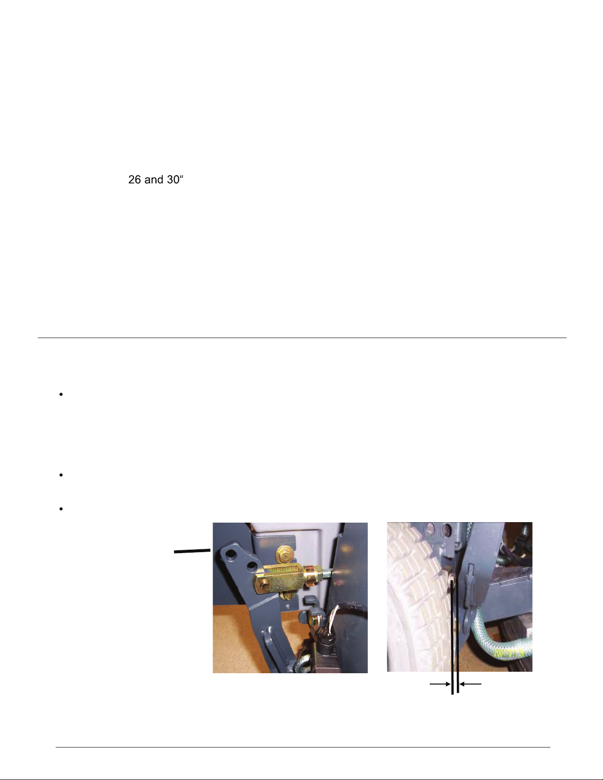
The lever provided is for lifting up the brush head. It features 3 positions for adjusting
the lift linkage (Fig. 6/1). The top hole is the transporting and ramp climbing position. In
this position, the lift linkage is to be adjusted so that a 1mm gap appears between the
lever and the screw head at the chassis (Fig. 6/2).
The middle hole position is for scrubbing with pads.
The bottom hole (Fig. 6/1) is the normal scrubing position of the brush head.
6. Brush Head Transport Position
1 mm Fig. 6/2
Transport Position
Scrubbing position
with pads
Scrubbing position
with brushes
Fig. 6/1
Table of contents
Other Hammerhead Scrubber manuals


Popular Scrubber manuals by other brands


Numatic
Numatic TTB 4045/100 Original instructions

U.S. Products
U.S. Products PEX 500-C-TICK Information & operating instructions

Mclennan
Mclennan C510 Operator's manual

Tennant
Tennant T20 LPG Operator's manual

Columbus
Columbus ARA 66 BM 100 operating manual

Numatic
Numatic TTV 678G / 300T Owner's instructions


