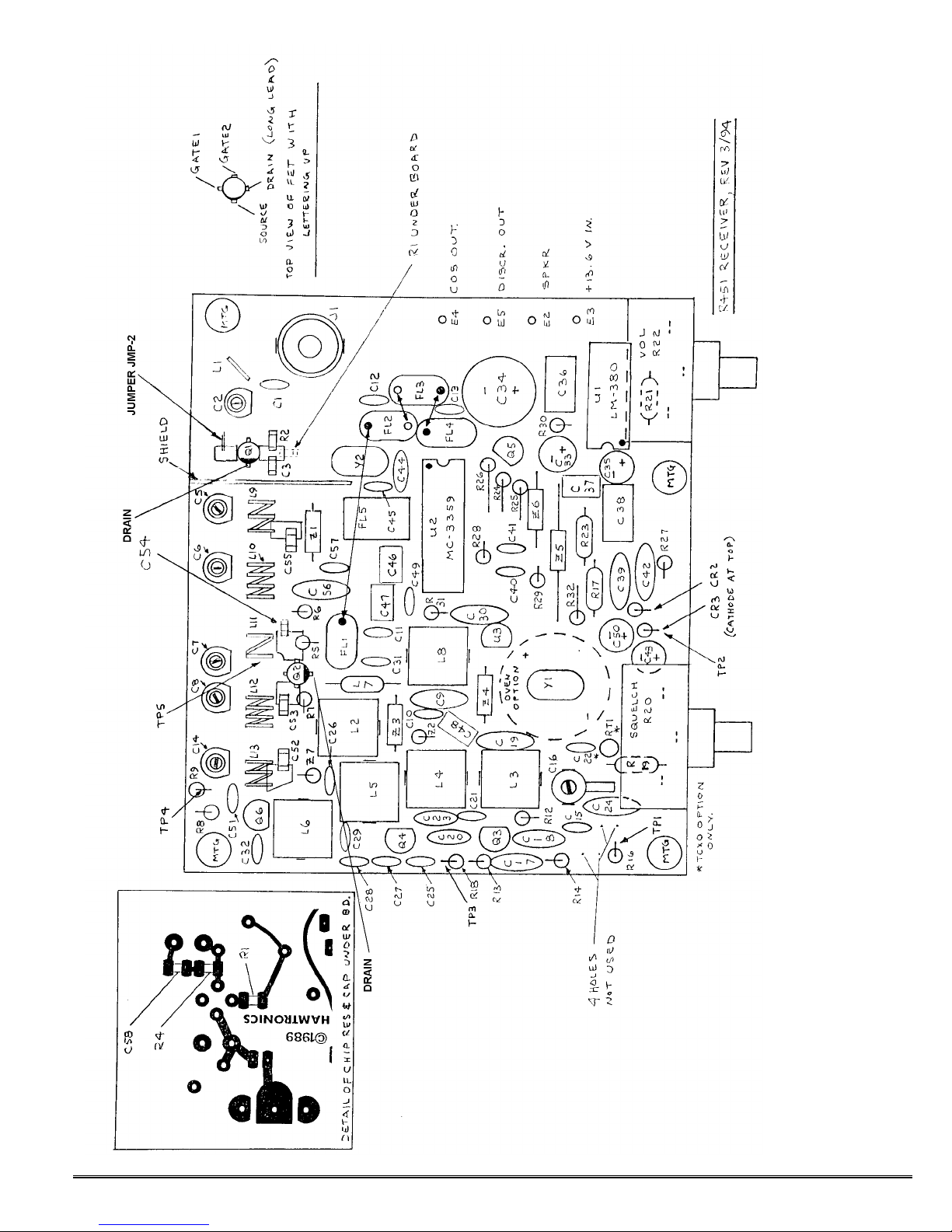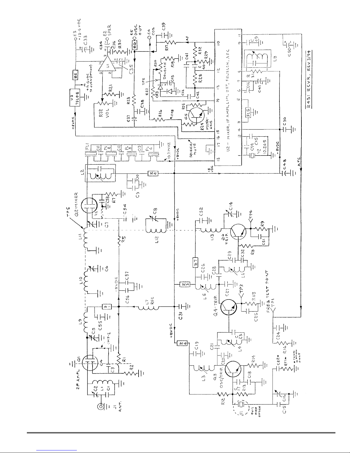
©1994 Hamtronics, Inc.; Hilton NY; USA. All rights reserved. Hamtronics is a registered trademark. Revised:
the receiver. A signal peak, there-
fore, is indicated by minimum noise
voltage, not maximum.
The other method is to use a
regular professional SINAD meter.
In either case, a weak to mod-
erate signal is required to observe
any change in noise. If the signal is
too strong, there will be no change in
the reading as tuning progresses; so
keep the signal generator turned
down as receiver sensitivity in-
creases during tuning.
If you use TP2 with a voltmeter,
the signal can be modulated or un-
modulated. If you use a SINAD me-
ter, the standard method is a 1000
Hz tone with 3 kHz deviation.
g. Check that signal generator is
still on 10.7000 MHz. With weak sig-
nal applied to Q2 gate-1 as before,
adjust L2 for minimum noise or dis-
tortion. This step is critical to get
lowest distortion in the crystal filter.
h. Remove signal generator so
the receiver hears just noise. Read-
just L8 slightly so that the voltage at
TP1 is +3.5V with just noise coming
through the i-f.
i. Connect signal generator to J1.
Adjust to exact channel frequency,
and turn output level up fairly high.
Adjust frequency trimmer capacitor
C16 to net the crystal to channel fre-
quency, indicated by +3.5Vdc at test
point TP1. If you can't find the signal
at all, tune your signal generator up
and down the band slightly. (Also
check that oscillator is peaked as per
step c.)
If your crystal has the wrong load
correlation or is slightly out of toler-
ance, you may be able to compensate
by changing the value of C15 so C16
can net the crystal on frequency.
The piston capacitor tuning range is
restricted to achieve best frequency
stability; so sometimes it may be
necessary to change the fixed ca-
pacitor. The proper adjustment re-
sults in +3.5Vdc, the same as preset
for the exact 10.700 MHz i-f fre-
quency earlier.
Maximum capacitance (lowest fre-
quency) occurs with the piston
screwed in all the way, and mini-
mum capacitance (highest frequency)
is with the piston all the way up. Be
careful not to completely remove the
piston. If the piston screw becomes a
little tight (squeaky), you can apply a
small amount of silicone oil to the
threads.
j. Connect fet dc voltmeter to TP2
(top lead of CR3). Set signal genera-
tor for relatively weak signal, one
which shows some change in the dc
voltage indication at TP2. Alternately
peak C14, C8, C7, C6, C5, and C2 un-
til no further improvement can be
made. On C8, you may get two peaks
over 180° rotation: a peak at the in-
jection frequency and a peak at the
signal frequency. The correct peak is
at the injection frequency, which oc-
curs at the setting of greater capaci-
tance (toward flat end of C8). Note
that the tuning of input variable ca-
pacitor C2 normally is very broad.
When properly tuned, sensitivity
should be about 0.2µV for 12 dB
SINAD.
SQUELCH CIRCUIT.
The squelch circuit has about 3 to
6 dB of hysteresis built in, so that
once the squelch opens, the signal
must drop 3 to 6 dB below the open-
ing threshold before squelching
again. This allows for some fading on
mobile stations and prevents squelch
pumping on heavy modulation. It also
prevents cycling due to slight de-
sense in repeater installations. Of
course, this requires setting the
threshold a little higher than if there
was no hysteresis so that it will close
with no signal. If you prefer the
older type squelch, you can simply
remove Q5 from the circuit; however,
this is not recommended for repeater
installations. If you want more or
less hysteresis, you can decrease or
increase the value of R25.
REPEATER USE.
E4 provides a "carrier operated
switch" output which may be con-
nected to a COR module to turn a
transmitter on and off. The output
level is about 7V unsquelched and 0V
squelched. There is a resistor in se-
ries with the output to limit current.
Refer to COR module instructions for
details.
If your repeater controller uses
discriminator audio, rather than the
speaker output, filtered discriminator
audio is available at E5. The level is
about 2V p-p. If you need audio
which is squelched, take it from the
input (right hand) terminal on the
VOLUME control.
AUDIO MUTING.
If the receiver is used as a part of
a transceiver, audio muting can be
accomplished without switching the
power or speaker lines. If the trans-
mitter is keyed by applying B+ to the
exciter, simply connect the keyed B+
through a 100K resistor to the junc-
tion of R25 and R27 on the receiver
board. The dc level will be sufficient
to trigger the squelch circuit in U2,
regardless of the rf signal level com-
ing into the receiver.
Of course, some means of discon-
necting the receiver from the an-
tenna must be provided, and we rec-
ommend our TRR Coax Relay Module
if the power level is under 25 Watts.
Otherwise, a larger coax relay will be
required.
DISCRIMINATOR METER.
If you wish to use a discriminator
meter and you are handy in de-
signing with op-amps, you can run a
sample of the dc voltage at DIS-
CRIMINATOR output terminal E5 to
one input of an op-amp and tie the
other input to a voltage divider pot
set to provide a reference voltage of
about +3.5Vdc.
S-METER.
There is no s-meter function, as
such, available in if amplifier ic's
made for professional receivers; how-
ever, a signal strength indication is
available at test point TP2. This volt-
age is a function of the noise level
detected in the squelch circuit. It is
about +3Vdc with no signal and 0Vdc
with full quieting. You can tap off
this point with a high-impedance cir-
cuit, such as an op-amp, to drive a
meter or a computerized repeater
controller.
SUBAUDIBLE TONE
DECODER.
To use our TD3 Subaudible Tone
Decoder or a similar module, connect
its audio input to DISCRIMINATOR
terminal E5. If you want to use it to
mute the audio (instead of inhibiting
a repeater transmitter as is normally
done), connect the mute output of
the TD-3 to the right-hand lug of the