©1998 Hamtronics, Inc.; Hilton NY; USA. All ri
hts reserved. Hamtronics is a re
istered trademark. Revised: 11/1/99 - Pa
e 6 -
is about +1Vdc to just under +8Vdc.
However, for optimum results, the vco
should be tuned to allow operation at
about +4Vdc center voltage.
d. Check the operating voltage
and bias on the vco and buffer.
e. Check the 10.240 MHz oscil-
lator or TCXO at pin 1 of the synthe-
sizer ic (actually best to check at top
lead of R3 or the pad which it would
be connected to; avoid trying to probe
surface mount ic leads which are
close together). A scope should show
strong signal (several volts p-p) at
10.240 MHz. If you are using a crys-
tal oscillator rather than an optional
TCXO, check to be sure the stator
leads of the piston trimmer capacitor
are not shorted to the ground plane.
f. Check the oscillator at pin 1 of
microcontroller ic U1 with a scope.
There should be a strong ac signal
(several volts p-p) at the oscillator fre-
quency.
g. The data, clock, and /enable
lines between the microcontroller and
synthesizer ic’s should show very brief
and very fast activity, sending data to
the synthesizer ic shortly after the
power is first applied or a dip switch
setting is changed. Because this hap-
pens very fast, it can be difficult to see
on a scope. Use 100µSec/div,
5Vdc/div, and normal trigger.
h. Check the microcontroller to
see that its /reset line is held low
momentarily when the power is first
applied. C1 works in conjunction
with an internal resistor and diode in
the ic to make C1 charge relatively
slowly when the power is applied. It
should take about a second to charge
up.i. Check the switch and E6-E7
jumper settings to be sure you have
the correct frequency information go-
ing to the microcontroller.
j. If you have a scope or spec-
trum analyzer, you can check the
output pin of the divide by 64
prescaler at pin 13 of U2. There
should be a strong signal (several
volts p-p) at about 2.25 MHz. If this
signal is absent, there may not be
sufficient level of sample signal from
the buffer at U2 pin 11. Be careful not
to short adjacent pins of the ic.
Microphonics, Hum, and Noise.
The vco and loop filter are very
sensitive to hum and noise pickup
from magnetic and electrical sources.
Some designs use a shielded com-
partment for vco’s. We assume the
whole board will be installed in a
shielded enclosure; so we elected to
keep the size small by not using a
separate shield on the vco. However,
this means that you must use care to
keep wiring away from the vco circuit
at the right side of the board. Having
the board in a metal enclosure will
shield these sensitive circuits from flo-
rescent lights and other strong
sources of noise.
Because the frequency of a synthe-
sizer basically results from a free run-
ning L-C oscillator, the tank circuit,
especially L1, is very sensitive to mi-
crophonics from mechanical noise
coupled to the coil. You should mini-
mize any sources of vibration which
might be coupled to the Receiver,
such as motors. In addition, it helps
greatly to prevent the molded coil from
vibrating with respect to the shield
can. Both the coil and can are sol-
dered to the board at the bottom, but
the top of the coil can move relative to
the can and therefore cause slight
changes in inductance which show up
as frequency modulation. Securing
the top of the plastic coil form to the
shield can with some type of cement
or nail polish greatly reduces the mi-
crophonic effects. This practice is
recommended in any installation
where vibration is a problem.
Excessive noise on the dc power
supply which operates the Receiver
can cause noise to modulate the syn-
thesizer output. Various regulators
and filters in the Receiver are de-
signed to minimize sensitivity to wir-
ing noise. However, in extreme cases,
such as in mobile installations with
alternator whine, you may need to
add extra filtering in the power line to
prevent the noise from reaching the
Receiver.
Other usual practices for mobile
installations are recommended, such
as connecting the + power and ground
return lines directly to the battery in-
stead of using cigarette lighter sockets
or dash board wiring.
To varying degrees, whine from the
5kHz reference frequency may be
heard on the signal under various cir-
cumstances. If the tuning voltage re-
quired to tune the vco on frequency is
very high or low, near one extreme,
the whine may be heard. This can
also happen even when the tuning
voltage is properly near the 4Vdc
center if there is dc loading on the
loop filter. Any current loading, no
matter how small, on the loop filter
causes the phase detector to pump
harder to maintain the tuning voltage.
The result is whine on the signal.
Such loading can be caused by con-
necting a voltmeter to TP2 for testing,
and it can also be caused by moisture
on the loop filter components.
Phase noise is a type of white noise
which phase locked loop synthesizers
produce. Many efforts are made dur-
ing the design of the equipment to re-
duce it as much as possible. The
phase noise in this unit should be al-
most as good as a crystal oscillator
radio. If you notice excessive white
noise even though the signal is strong,
it may be caused by a noisy vco tran-
sistor, Q1. Try swapping with the
buffer transistor, Q2, which is the
same type and see if that helps.
When using a replacement transistor
for repairs, be sure to use one of good
quality.
If you suspect noise is being intro-
duced in the synthesizer, as opposed
to the signal path from the antenna to
the detector, you can listen to the in-
jection signal at 10.700 MHz below
the channel frequency on a receiver or
service monitor and hear what just
the injection signal sounds like. Put a
pickup lead on top of the Receiver
board so you have a strong sample to
hear so you are sure the noise is not
due to weak signal pickup at the test
receiver.
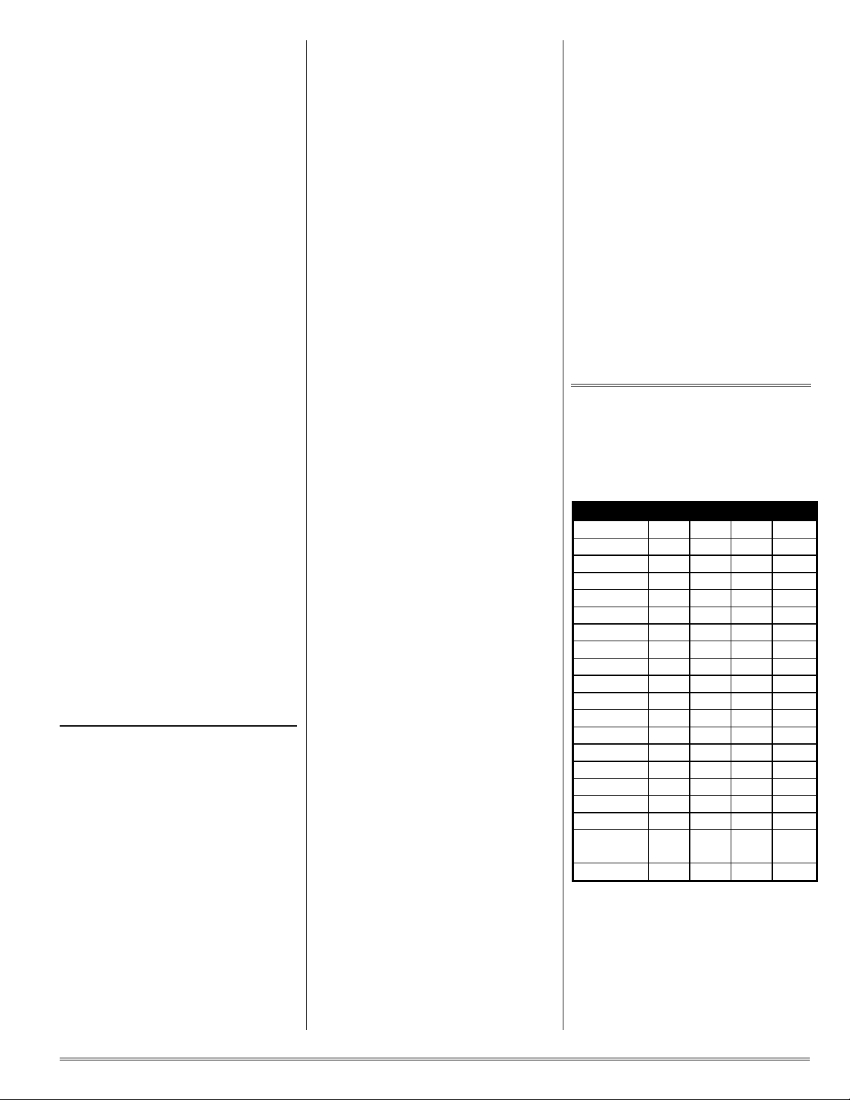
Typical Dc Voltages.
Tables 4-6 give dc levels measured
with a sensitive dc voltmeter on a
sample unit with 13.6 Vdc B+ applied.
All voltages may vary considerably
without necessarily indicating trouble.
The charts should be used with a logi-
cal troubleshooting plan. All voltages
are positive with respect to ground
except as indicated.
Use caution when measuring volt-
ages on the surface mount ic. The
pins are close together, and it is easy
to short pins together and damage the
ic. We recommend trying to connect
meter to a nearby component con-
nected to the pin under question.
Also, some pins are not used in this
design, and you can generally not be
concerned with making measure-
ments on them.
Typical Audio Levels.
Table 7 gives rough measurements
of audio levels.. Measurements were
taken using an oscilloscope, with no
input signal, just white noise so con-
ditions can be reproduced easily.
REPAIRS.
If you need to unsolder and replace