manuals.online logo
Brands
  1. Home
  2. •
  3. Brands
  4. •
  5. HAMTRONICS
  6. •
  7. Receiver
  8. •
  9. HAMTRONICS R451 Owner's manual

HAMTRONICS R451 Owner's manual

©1994 Hamtronics, Inc.; Hilto
n NY; USA. All rights reserved. Hamtronics is a registered trademark. evised:
10/2/07
-
Page
1
-
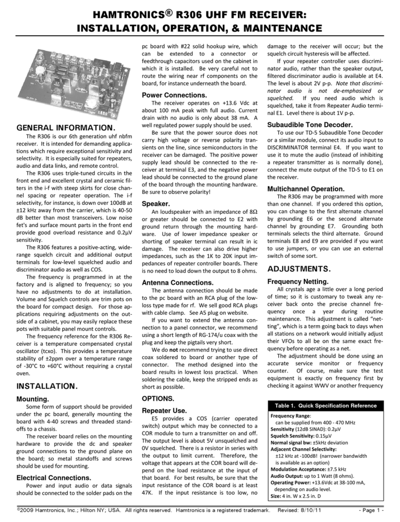
FUNCTIONAL DESCRIPTION.
The R451 is a premium, com-
mercial- grade single-channel uhf fm
receiver. It features a GaAs F T rf
amplifier for very good sensitivity, an
8-pole crystal filter plus a ceramic fil-
ter for superior i-f selectivity, and a
hysteresis squelch circuit to lock onto
fading signals.
The R451 kit is available for the
420-470 MHz band, and wired units
are available for this band and also
the commercial and government
bands directly above and below this
range.
CRYSTALS.
The channel crystal plugs into
sockets identified in component lo-
cation diagram as Y1. We can order
crystals for any frequency desired. If
you order your own, be sure to supply
these specs.
The receiver uses 32 pF parallel
resonant crystals in HC-25/u holders.
Crystals operate in the fundamental
mode at a frequency of (F-10.7)/27.
Frequency tolerance is .001%. We
recommend that any new crystals be
ordered directly from us to be sure
that they will perform properly over
the -30 to +60°C range for which the
unit was designed. This is especially
true for commercial receivers with the
temperature-compensated crystal os-
cillator (TCXO) option, since the crys-
tal must be matched exactly to the
compensation circuit in the receiver.
If you use an OV-1 crystal oven, spec-
ify a crystal with a 60°C breakpoint.
POWER CONNECTIONS.
The receiver operates on +13.6 Vdc
at about 150 mA peak with full audio.
Current drain with no audio is only
35-40 mA. A crystal oven adds about
450 mA peak current drain when cold
and only about 25 mA when warm. A
well regulated power supply should be
used.
Be sure that the power source does
not carry high voltage or reverse po-
larity transients on the line, since
semiconductors in the receiver can be
damaged. The positive power supply
lead should be connected to the re-
ceiver at terminal 3, and the negative
power lead should be connected to the
ground plane of the board through the
mounting hardware or the shield of
the coaxial cable. Be sure to observe
polarity!
SPEAKER.
An 8Ω loudspeaker should be con-
nected to 2 with ground return to
the ground plane through the mount-
ing hardware. Use of lower imped-
ance speaker or shorting of speaker
terminal can result in ic damage. The
receiver can also drive higher imped-
ances, like 1K to 10K input imped-
ances of COR boards, etc. There is no
need to load down the output to 8Ω.
Note that the audio output ic is de-
signed to be heat sunk to the pc board
through the many ground pins on the
ic. When running moderately low au-
dio levels as most applications re-
quire, it is no problem to use an ic
socket; so we have provided one for
your convenience. If you will be run-
ning high audio levels, check to see if
the ic is getting hot. If so, you should
remove the ic socket, and solder the
LM-380 ic directly to the board for
better heatsinking.
ANTENNA CONNECTIONS.
The antenna connection should be
made to the receiver with a phono
plug. If you want to extend the an-
tenna connection to a panel connec-
tor, we recommend using a short
length of RG-174/u coax and a good
phono plug with cable clamp (see
catalog). We do not recommend trying
to use direct coax soldered to board or
another type of connector. The
method designed into the board re-
sults in lowest loss practical. When
soldering the cable, keep the stripped
ends as short as possible.
ALIGNMENT.
quipment needed for alignment is
an fet voltmeter, an rf signal genera-
tor, a regulated 13.6Vdc power supply
with a 0-200 mA meter internally or
externally connected in the supply
line.
The slug tuned coils in the receiver
should be adjusted with the proper
.062" square tuning tool to avoid
cracking the powdered iron slugs.
Variable capacitors should be ad-
justed with a plastic tool with a small
metal bit on the end. Tools are avail-
able for adjusting the rf coils (model
A28) and for variable capacitors
(model A2).
Unless already tuned once, vari-
able capacitors C1, C5-C8, and C14
should be set to midrange, as in-
dicated by the slot on the rotor being
aligned with the ends of the capacitor
(as illustrated for C6 in the parts loca-
tion diagram). The SQU LCH pot
should be set fully counterclockwise.
a. Install channel crystal in socket
Y1.
b. Connect speaker and +13.6
Vdc. You should hear white noise.
c. Connect dc voltmeter to TP3
(top lead of R18). Adjust first L4, then
L3 and L4 alternately for maximum
response. (Typical indication is about
+1.5 Vdc.)
d. Connect dc voltmeter to TP4
(top lead of R9). Adjust L5 and L6 al-
ternately for maximum response.
(Typical indication is about +1.5 Vdc.)
e. Connect stable signal gener-
ator to TP5 (left end of coil L11), using
coax clip lead. Set generator to exactly
10.7000 MHz. Use a frequency
counter or synthesized signal genera-
tor. Set level just high enough for full
quieting. (At 5-10 uV, you should no-
tice some quieting, but you need
something near full quieting for the
test.
f. Connect dc voltmeter to TP1 (top
lead of R16). Adjust discriminator
transformer L8 for +3.5Vdc. Note that
the voltage changes very rapidly with
tuning. Full swing of about 1 to 8V
occurs within a few kHz.
Note: There are two methods of
adjusting the mixer and front end.
One is to use an fet voltmeter with test
point TP2, which is the top lead of
CR3. The voltage at this point is pro-
portional to the amount of noise de-
tected in the squelch circuit; so it
gives an indication of the quieting of
the receiver. A signal peak, therefore,
is indicated by minimum noise volt-
age, not maximum.
The other method is to use a regu-
lar professional SINAD meter.
In either case, a weak to moderate
signal is required to observe any
change in noise. If the signal is too
strong, there will be no change in the
reading as tuning progresses; so keep
the signal generator turned down as
receiver sensitivity increases during
tuning.
If you use TP2 with a voltmeter,
the signal can be modulated or un-
modulated. If you use a SINAD meter,
the standard method is a 1000 Hz
tone with 3 kHz deviation.
g. Check that signal generator is
HAMTRONICS

 R451 UHF FM RECEIVER:
INSTALLATION, OPERATION, & MAINTENANCE
©1994 Hamtronics, Inc.; Hilto
n NY; USA. All rights reserved. Hamtronics is a registered trademark. evised:
10/2/07
-
Page
2
-
still on 10.7000 MHz. With weak sig-
nal applied to Q2 gate-1 as before, ad-
just L2 for minimum noise or
distortion. This step is critical to get
lowest distortion in the crystal filter.
h. Remove signal generator so the
receiver hears just noise. Readjust L8
slightly so that the voltage at TP1 is
+3.5V with just noise coming through
the i-f.
i. Connect signal generator to J1.
Adjust to exact channel frequency,
and turn output level up fairly high.
Adjust frequency trimmer capacitor
C16 to net the crystal to channel fre-
quency, indicated by +3.5Vdc at test
point TP1. If you can't find the signal
at all, tune your signal generator up
and down the band slightly. (Also
check that oscillator is peaked as per
step c.)
If your crystal has the wrong load
correlation or is slightly out of toler-
ance, you may be able to compensate
by changing the value of C15 so C16
can net the crystal on frequency. The
piston capacitor tuning range is re-
stricted to achieve best frequency sta-
bility; so sometimes it may be
necessary to change the fixed ca-
pacitor. The proper adjustment re-
sults in +3.5Vdc, the same as preset
for the exact 10.700 MHz i-f frequency
earlier.
Maximum capacitance (lowest fre-
quency) occurs with the piston
screwed in all the way, and minimum
capacitance (highest frequency) is
with the piston all the way up. Be
careful not to completely remove the
piston. If the piston screw becomes a
little tight (squeaky), you can apply a
small amount of silicone oil to the
threads.
j. Connect fet dc voltmeter to TP2
(top lead of CR3). Set signal generator
for relatively weak signal, one which
shows some change in the dc voltage
indication at TP2. Alternately peak
C14, C8, C7, C6, C5, and C2 until no
further improvement can be made.
On C8, you may get two peaks over
180° rotation: a peak at the injection
frequency and a peak at the signal
frequency. The correct peak is at the
injection frequency, which occurs at
the setting of greater capacitance (to-
ward flat end of C8). Note that the
tuning of input variable capacitor C2
normally is very broad.
When properly tuned, sensitivity
should be about 0.2µV for 12 dB
SINAD.
SQUELCH CIRCUIT.
The squelch circuit has about 3 to
6 dB of hysteresis built in, so that
once the squelch opens, the signal
must drop 3 to 6 dB below the open-
ing threshold before squelching again.
This allows for some fading on mobile
stations and prevents squelch pump-
ing on heavy modulation. It also pre-
vents cycling due to slight desense in
repeater installations. Of course, this
requires setting the threshold a little
higher than if there was no hysteresis
so that it will close with no signal. If
you prefer the older type squelch, you
can simply remove Q5 from the cir-
cuit; however, this is not recom-
mended for repeater installations. If
you want more or less hysteresis, you
can decrease or increase the value of
R25.
REPEATER USE.
4 provides a "carrier operated
switch" output which may be con-
nected to a COR module to turn a
transmitter on and off. The output
level is about 7V unsquelched and 0V
squelched. There is a resistor in se-
ries with the output to limit current.
Refer to COR module instructions for
details.
If your repeater controller uses dis-
criminator audio, rather than the
speaker output, filtered discriminator
audio is available at 5. The level is
about 2V p-p. If you need audio
which is squelched, take it from the
input (right hand) terminal on the
VOLUM control.
AUDIO MUTING.
If the receiver is used as a part of a
transceiver, audio muting can be ac-
complished without switching the
power or speaker lines. If the trans-
mitter is keyed by applying B+ to the
exciter, simply connect the keyed B+
through a 100K resistor to the junc-
tion of R25 and R27 on the receiver
board. The dc level will be sufficient
to trigger the squelch circuit in U2,
regardless of the rf signal level coming
into the receiver.
Of course, some means of discon-
necting the receiver from the antenna
must be provided, and we recommend
our TRR Coax Relay Module if the
power level is under 25 Watts. Other-
wise, a larger coax relay will be re-
quired.
DISCRIMINATOR METER.
If you wish to use a discriminator
meter and you are handy in designing
with op-amps, you can run a sample
of the dc voltage at DISCRIMINATOR
output terminal 5 to one input of an
op-amp and tie the other input to a
voltage divider pot set to provide a ref-
erence voltage of about +3.5Vdc.
S-METER.
There is no s-meter function, as
such, available in if amplifier ic's
made for professional receivers; how-
ever, a signal strength indication is
available at test point TP2. This volt-
age is a function of the noise level de-
tected in the squelch circuit. It is
about +3Vdc with no signal and 0Vdc
with full quieting. You can tap off this
point with a high-impedance circuit,
such as an op-amp, to drive a meter
or a computerized repeater controller.
SUBAUDIBLE TONE
DECODER.
To use our TD3 Subaudible Tone
Decoder or a similar module, connect
its audio input to DISCRIMINATOR
terminal 5. If you want to use it to
mute the audio (instead of inhibiting a
repeater transmitter as is normally
done), connect the mute output of the
TD-3 to the right-hand lug of the vol-
ume control.
MOUNTING.
Some form of support should be
provided under the pc board, gener-
ally mounting the board with spacers
to a chassis. 3/8-inch holes should
be provided in a front panel for the
bushings of the SQU LCH and VOL-
UM controls. After sliding bushings
through panel, washers and nuts can
be installed on the outside of the
panel. Be sure to provide support for
the board; do not rely on the controls
to support the board.
For repeater applications, the re-
ceiver should be mounted in an rf
tight box, such as our model A16.
The receiver board relies on the
mounting hardware to provide the dc
and speaker ground connections to
the ground plane on the board.
TROUBLESHOOTING.
The usual troubleshooting tech-
niques of checking dc voltages and
signal tracing work well in trou-
bleshooting the receiver. A dc voltage
chart and a list of typical audio levels
are given to act as a guide to trou-
bleshooting. Although voltages may
vary widely from set to set and under
various operating and measurement
conditions, the indications may be
helpful when used in a logical trou-
bleshooting procedure.
The most common troubles in all
kits are interchanged components,
©1994 Hamtronics, Inc.; Hilto
n NY; USA. All rights reserved. Hamtronics is a registered trademark. evised:
10/2/07
-
Page
3
-
cold solder joints, and solder
splashes. Another common trouble is
blown transistors and ic's due to re-
verse polarity or power line transients.
Remember if you encounter problems
during initial testing that it is easy to
install parts in the wrong place. Don't
take anything for granted. Double
check everything in the event of trou-
ble.
If the receiver is completely dead,
try a 10.700 MHz signal applied to
TP5 (left side of coil L11) with a coax
cable clip lead. You should be able to
hear the quieting effect of a 20-30 uV
carrier at 10.700 MHz. You can also
connect the 10.700 MHz clip lead
through a blocking capacitor to vari-
ous sections of the crystal filter to see
if there is a large loss of signal across
one of the filter sections. Also, check
the 10.245 MHz oscillator with a
scope or by listening with an hf re-
ceiver or service monitor.
A signal generator on the channel
frequency can be injected at various
points in the front end. If the mixer is
more sensitive than the rf amplifier,
the rf stage is suspect. Check the dc
voltages looking for a damaged fet.
If audio is present at the VOLUM
control but not at the speaker, the
audio ic may have been damaged by
reverse polarity or a transient on the
B+ line. If no audio is present on the
volume control, the squelch circuit
may not be operating properly. Check
the dc voltages, and look for noise in
the 10 kHz region, which should be
applied to noise detector CR2/CR3
with no input signal. (Between pins
12 and 13 of U2 is an op amp active
filter tuned to 10 kHz.)
Typical Dc Voltages.
The dc levels in Table 1 were mea-
sured with an 11 megohm fet vm on
a sample unit with 13.6 Vdc B+ ap-
plied. All voltages may vary con-
siderably without necessarily
indicating trouble. The chart should
be used with a logical troubleshooting
plan. All voltages are positive with
respect to ground except as indi-
cated. Voltages are measured with
no signal applied but oscillator run-
ning properly and with squelch open
unless otherwise specified.
Typical Audio Levels.
Following are rough measure-
ments of audio circuits, using an os-
cilloscope. Measurements were taken
under two conditions. The first is
with no input signal, just white noise
so conditions can be reproduced eas-
ily. The second is with an input sig-
nal having a 1000 Hz tone modulated
±3kHz.
TABLE 1. TYPICAL DC VOLTAGES.
Xstr E(S)B(G1)C(D) G2
Q1 0 0 8 4
Q2 1.5 0 8 4
Q3 4 4 8 -
Q4 1.5 0 8 -
Q5 Squelched 0 0 0.7 -
Q5 Unsq 0 0.7 0 -
Q6 1.5 0 8 -
U1 1 6 8 14
7 0 7 13.6
U2 1 2 3 4 5 6 7 8
7.9 7.2 7.2 8 1.1 1.1 1.1 8
U2 9 10 11 12 13 14
4.4 3.5 1 To 8 2.5 2.5 .3 To .7
U2 . 15 16 17 18
0(Sq), 7.2(Unsq) 0 0 2.3
TABLE 2. TYPICAL AUDIO LEVELS (V p-p)
Measured At On Noise On Tone
U2 pin 10 (discrim.): 4 2
E5 (discriminator out): 3 1.5
U2 pin 13 (noise ampl): 4 0.4
Top of volume control: 0.8 0.2
Across 8Ωspkr term: 12 10
©1994 Hamtronics, Inc.; Hilto
n NY; USA. All rights reserved. Hamtronics is a registered trademark. evised:
10/2/07
-
Page
4
-
PARTS LIST FOR R451 RCVR
➊indicates surface mount part under
board.
➋Due to parts shortage, it is neces-
sary to use two 6.8k resistors in se-
ries; join them at the top and tack
solder leads together.
➌Note: disc cap is no longer available
in this value. Carefully tack solder
surface mount capacitor on bottom of
board. Hold it carefully with tweezers
to avoid dropping it.
Ref # Value (marking)
C1 6 pf
C2 4.5 pf variable (white)
C3 .01 uf chip capacitor
C4 not assigned
C5-C8 4.5 pf variable (white)
C9 .01 uf disc (103)
C10 .001 uf (102, 1nM, or 1nK)
C11 7 pf
C12 7 pf
C13 8 pf
C14 4.5 pf variable (white)
C15 39 pf
C16 Piston trimmer, 2-11.2 pf
C17-C18➌150 pf 1206 chip cap
C19 .001 uf (102, 1nM, or 1nK)
C20 62 pf
C21 2 pf
C22 7 pf (TXCO option only -
see text)
C23 62 pf
C24 .01 uf disc (103)
C25 220 pf
C26 .001 uf (102, 1nM, or 1nK)
C27 18 pf
C28➌0.5 pf chip cap
C29 33 pf
C30 .01 uf disc (103)
C31 .001 uf (102, 1nM, or 1nK)
C32 33 pf
C33 47 uf electrolytic
C34 470 uf electrolytic
C35 4.7 uf electrolytic
C36 0.15 uf mylar (red)
C37 0.1 uf monolithic (104)
C38 0.15 uf mylar (red)
C39 .01 uf disc (103)
C40-C41 .001 uf (102, 1nM, or 1nK)
C42 .01 uf disc (103)
C43 0.47 uf electrolytic
C44 62 pf
C45 220 pf (221)
C46-C48 0.1 uF monolithic (104)
C49 100pf (101) or 120pf (121)
C50 0.47 uf electrolytic
C51 30 pf
C52 68 pf chip capacitor
C53-C54 .01 uf chip capacitor
C55 68 pf chip capacitor
C56 .01 uf disc (103)
C57 30 pf
C58 not used
CR1 not used
CR2-CR3 1N4148 (may not be
marked)
E1 Not assigned
FL1-FL4 Matched xtal filter set
FL5 Ceramic filter LT-455DW
J1 RCA jack
JMP-1&2 Jumper - see diagram
L1 ¾ turn loop #20 bus
L2 7A-691F IF transformer
L3-L4 6-1/2 turns (blue)
L5-L6 2-1/2 turns (red)
L7 0.33 uH rf choke (red-sil-
orn-orn)
L8 IF transformer p/n 831-5 or
YMC-15002 or T1003
L9 2¾ turns #20 bus
L10 3¾ turns #20 bus
L11 1¾ turns #20 bus
L12 3¾ turns #20 bus
L13 2¾ turns #20 bus
Q1-Q2 N.E.C. 3SK122 MOS FET
(static handling precau-
tions required.)
Q3-Q5 2N5770 or
2N3904
Q6 PN5179
R1➊68K chip resistor
R2➊68K chip resistor
R3-R4 Not assigned
R5-R6 100K
R7 180 ohms
R8 1K
R9 270 ohms
R10-R11 Not assigned
R12➊10K
R13 4.7K
R14 270 ohms
R15 not used
R16 330K
R17 1K
R18 270 ohms
R19 27K
R20 100K pot
R21 27K
R22 100K pot
R23 6.8K
R24 510K
R25 100K
R26 3.3K
R27 100K
R28 330K
R29 680 ohms
R30 3.3Ω(orn-orn-gold-gold)
R31 68K
R32➋15K (see note)
RT1 Thermistor (TXCO option
only - see text)
U1 LM-380N Spkr Amplifier
U2 MC-3359P IF Amplifier
U3 78L08 +8Vdc Regulator
Y1 Channel xtal (see text)
Y2 10.245 MHz, 62 pf IF xtal
Z1-Z7 Ferrite beads
©1994 Hamtronics, Inc.; Hilto
n NY; USA. All rights reserved. Hamtronics is a registered trademark. evised:
10/2/07
-
Page
5
-
©1994 Hamtronics, Inc.; Hilto
n NY; USA. All rights reserved. Hamtronics is a registered trademark. evised:
10/2/07
-
Page
6
-

Other HAMTRONICS Receiver manuals

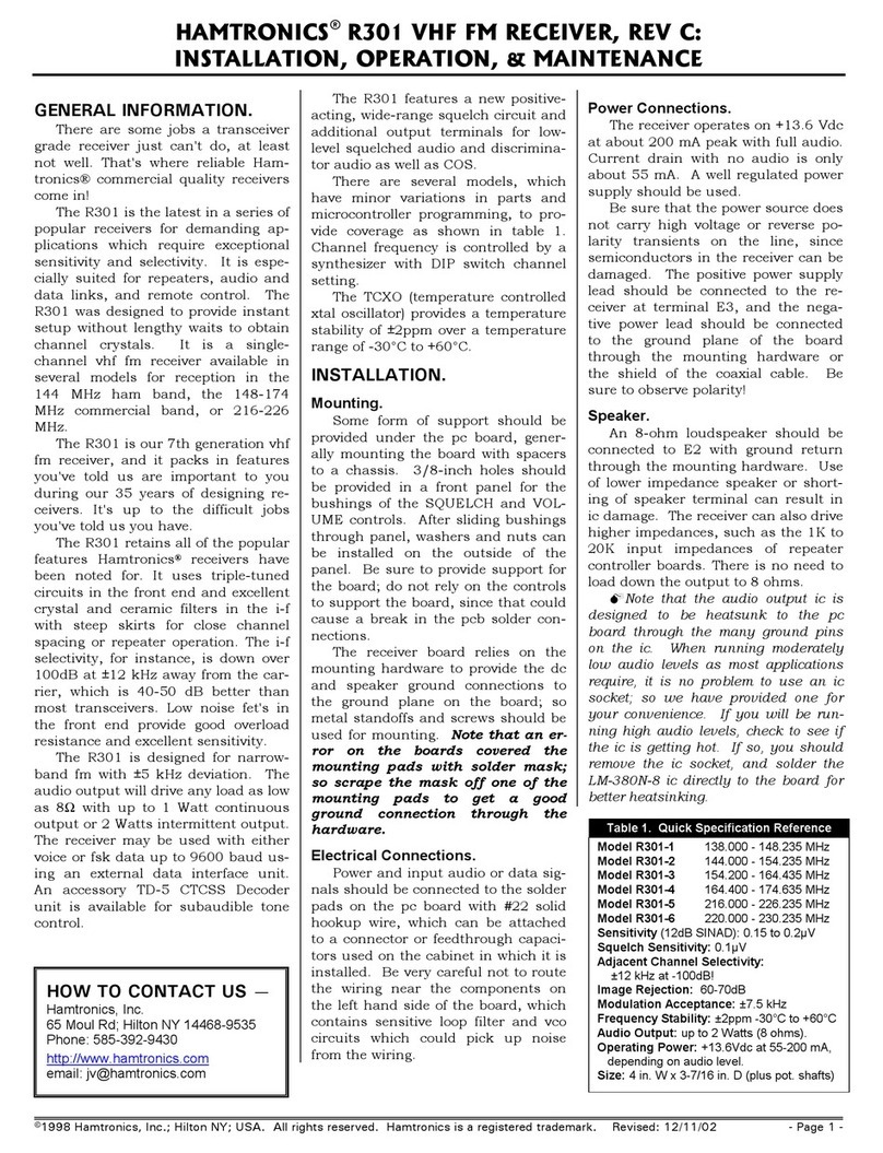
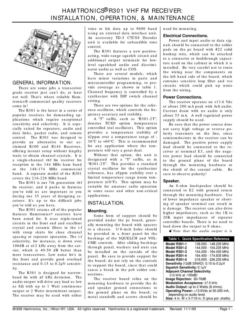
HAMTRONICS R301 Owner's manual

HAMTRONICS

HAMTRONICS R301 Owner's manual

HAMTRONICS R451 Owner's manual

HAMTRONICS

HAMTRONICS R451 Owner's manual

HAMTRONICS R100 User manual

HAMTRONICS

HAMTRONICS R100 User manual

HAMTRONICS R100 User manual

HAMTRONICS

HAMTRONICS R100 User manual

HAMTRONICS R301 Owner's manual

HAMTRONICS

HAMTRONICS R301 Owner's manual

HAMTRONICS R303-137 Owner's manual

HAMTRONICS

HAMTRONICS R303-137 Owner's manual

HAMTRONICS R303 Owner's manual

HAMTRONICS

HAMTRONICS R303 Owner's manual

HAMTRONICS R306 Installation and operating instructions

HAMTRONICS

HAMTRONICS R306 Installation and operating instructions

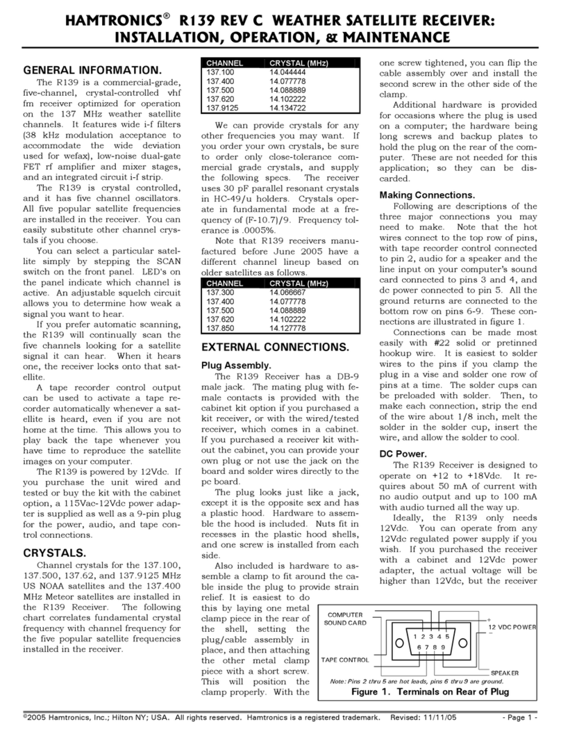
HAMTRONICS R139 Owner's manual

HAMTRONICS

HAMTRONICS R139 Owner's manual

HAMTRONICS R302 Series Owner's manual

HAMTRONICS

HAMTRONICS R302 Series Owner's manual

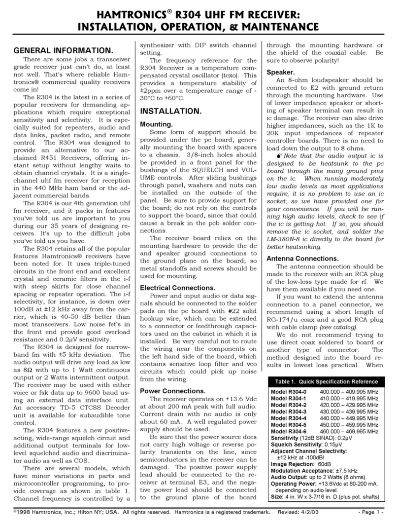
HAMTRONICS r304 Owner's manual

HAMTRONICS

HAMTRONICS r304 Owner's manual

Popular Receiver manuals by other brands

Install Bay IBR65 user manual

Install Bay

Install Bay IBR65 user manual

Hall Research Technologies EX-4KU user manual

Hall Research Technologies

Hall Research Technologies EX-4KU user manual

Pioneer VSX-D811S Service manual

Pioneer

Pioneer VSX-D811S Service manual

Marantz SR5500 FULL LINE CATALOG

Marantz

Marantz SR5500 FULL LINE CATALOG

Pioneer SPH-10BT Firmware update instructions

Pioneer

Pioneer SPH-10BT Firmware update instructions

FRIENDCOM FC-301/D user manual

FRIENDCOM

FRIENDCOM FC-301/D user manual

Harman Kardon AVR 355 owner's manual

Harman Kardon

Harman Kardon AVR 355 owner's manual

Marantz SR5013 Service manual

Marantz

Marantz SR5013 Service manual

Meinberg RU226 Information sheet

Meinberg

Meinberg RU226 Information sheet

LG LH-W750TA Service manual

LG

LG LH-W750TA Service manual

Nedo COMMANDER H2N operating instructions

Nedo

Nedo COMMANDER H2N operating instructions

TechniSat ST 6002 S operating instructions

TechniSat

TechniSat ST 6002 S operating instructions

Konig DVB-S2 REC10 user manual

Konig

Konig DVB-S2 REC10 user manual

Teradek Bolt 4K LT quick start guide

Teradek

Teradek Bolt 4K LT quick start guide

Velleman BTR1 user manual

Velleman

Velleman BTR1 user manual

CVW BeamLink-Ultimate user manual

CVW

CVW BeamLink-Ultimate user manual

Pioneer SPH-T20BT owner's manual

Pioneer

Pioneer SPH-T20BT owner's manual

LG HT905TA owner's manual

LG

LG HT905TA owner's manual

manuals.online logo
manuals.online logoBrands
  • About & Mission
  • Contact us
  • Privacy Policy
  • Terms and Conditions

Copyright 2025 Manuals.Online. All Rights Reserved.