Hamworthy Trigon ST1 Operation manual

Hamworthy Trigon
ST1 Solar Pump Station
Installation, Commissioning,
Operation & Service Instructions
IMPORTANT NOTE
THESE INSTRUCTIONS MUST BE READ
AND UNDERSTOOD BEFORE INSTALLING,
COMMISSIONING, OPERATING OR
SERVICING EQUIPMENT

Technical Enquiries
To supplement the detailed technical brochures, technical advice on the application and use of products in the Hamworthy
Heating range is available from our technical team in Poole and our accredited agents.
Site Assembly
Hamworthy offer a service of site assembly for many of our products where plant room access is restricted. Using our trained staff
we offer a higher quality of build and assurance of a boiler built and tested by the manufacturer.
Commissioning
Commissioning of equipment by our own engineers, accredited agents or specialist sub-contractors will ensure the equipment is
operating safely and efciently.
Service Contracts
Regular routine servicing of equipment by Hamworthy service engineers inspects the safety and integrity of the plant, reducing the
risk of failure and improving performance and efciency. Service contracts enable you to plan and budget more efciently.
Breakdown service, repair, replacement
Hamworthy provide a rapid response breakdown, repair or replacement service through head ofce at Poole and accredited
agents throughout the UK.
Spare Parts
We offer a comprehensive range of spare parts, providing replacement parts for both current and discontinued products. Delivery
options are available to suit you. Please refer to our website for more details.
Customer After Sales Services

HAMWORTHY HEATING LTD Page
TRIGON SOLAR THERMAL 500001281/A
1
i
NOTE: THESE INSTRUCTIONS MUST BE READ AND UNDERSTOOD BEFORE
INSTALLING, COMMISSIONING, OPERATING OR SERVICING THIS EQUIPMENT.
THE TRIGON ST1 SOLAR PUMP STATION COMPLIES WITH ALL RELEVANT EUROPEAN DIRECTIVES.
PUBLICATION NO. 500001281
ISSUE ‘A’
JUNE 2013
Hamworthy Trigon
ST1 Solar Pump Station
Installation, Commissioning,
Operation & Service Instructions

0DNO0201 Installation-Operation ST1 Solar Pump Station 1
HAMWORTHY TRIGON
INSTALLATION AND
OPERATION MANUAL
SOLAR PUMP STATION ST1
Customer Service Centre
Hamworthy Heating Limited
Fleets Corner, Poole,
Dorset BH17 0HH l

1 General information
2 Installation-Operation ST1 Solar Pump Station 0DNO0201
Item no. 0DNO0201
Translation of the original instructions
We reserve the right to make technical changes without notice!
Printed in Germany – Copyright by Hamworthy

1 General information
0DNO0201 Installation-Operation ST1 Solar Pump Station 3
Contents
1General information.........................................................................................................4
1.1 About these instructions...............................................................................................4
1.2 About this product........................................................................................................4
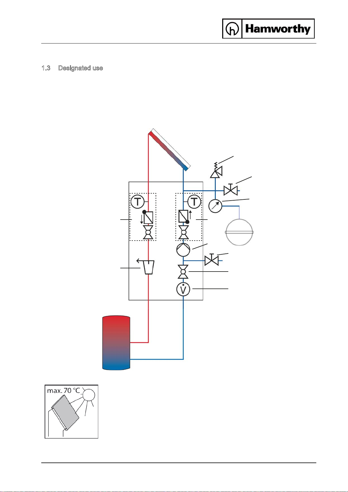
1.3 Designated use............................................................................................................5
2Safety instructions...........................................................................................................6
3Assembly and installation [installer]..................................................................................8
4Commissioning [installer]...............................................................................................11
4.1 Flushing and filling the solar circuit.............................................................................12
4.2 Preparations before flushing.......................................................................................14
4.3 Flushing and filling .....................................................................................................14
4.4 Setting the solar installation (only for standard solar pumps)......................................17
5Maintenance [installer]...................................................................................................18
5.1 Draining the solar installation .....................................................................................18
5.2 Disassembly...............................................................................................................18
6Spare parts [installer].....................................................................................................19
6.1 ST1 Solar Pump Station.............................................................................................19
Controller extension..............................................................................................................20
720
Technical data
...............................................................................................................
7.1 Pressure drop characteristics ST1 Solar Pump Station..............................................21
8Function check valves [installer].....................................................................................22
9Commissioning report....................................................................................................
24

1 General information
4 Installation-Operation ST1 Solar Pump Station 0DNO0201
1 General information
Carefully readthese instructions before installation and commissioning. Save these
instructions in the vicinity of the installation for future reference.
1.1 About these instructions
These instructions describe the installation, commissioning, function and operation of the
TRIGON ST1 Solar Pump Station. The chapters called [installer] are intended for installers only.
For other components of the solar thermal system such as collectors, tanks, expansion vessels
and controllers, please refer to the instructions for that component.
1.2 About this product
The station is a premounted fitting group checked for leakage used to circulate the solar fluid in
the solar circuit. It is mounted on a wall bracket and fixed with clips. The solar station is
optionally equipped with a controller. It contains importantfittings and safety devices for the
operation of the installation:
•Ball valves in the flow line (1.1) and return line (5.1)
•Check valves in the flow (1.1) and return ball valves (5.1)
•Thermometers in the flow (5.2) andreturn line (1.2)
•Pressure gauge to display the installation pressure (1.6)
•Flowmeter to display the flow rate (3.3)
•Ball valve to reduce the flow rate (3.1)
•Solar pressure relief valve (1.3)
•De-aerator to easily vent the solar circuit (4.2)
•Drain (3.2) andfill valves (1.4) with hose connectors

1 General information
0DNO0201 Installation-Operation ST1 Solar Pump Station 5
1.3 Designated use
The solar station may only be used as a pump station in the solar circuit taking into
consideration the technical limit values indicated in these instructions. Due to its design the
station must be mounted and operated as described in these instructions!
Improper usage excludes any liability claims.
When the sun shines, the collector can become very hot. The solar fluid
in the circuit can heat up to more than 100 °C.
Only flush and fill the solar circuit whenthe collector temperatures are
below 70 °C.
Flow
Return
5.1 1.1
5.2 1.2
1.3
1.4
1.5
1.6
2
3.2
3.1
3.3
3.4
4.1
4.2

2 Safety instructions
6 Installation-Operation ST1 Solar Pump Station 0DNO0201
2 Safety instructions
The installation and commissioning as well as the connection of electrical components require
technical knowledge commensurate with a recognised vocational qualification as a fitter for
plumbing, heating and air conditioning technology, or a profession requiring a comparable level
of knowledge [installer]. The following must be observed during installation and commissioning:
•relevant local and national regulations
•accident prevention regulations of the professional association
•instructions and safety instructions mentioned in this manual
WARNING
Danger of scalding due to vapour escape!
With pressure relief valves there is risk of scalding due to vapour escape. During
installation, check the local conditions and if a discharge line must be connected
to the safety group.
Observe the instructions regarding the pressure relief valve.
The pressures calculated by the installation planner for the expansion
vessel and the operating pressure of the installation must be set.
CAUTION
Risk of burns!
The valves, fittings and the pump may heat up to more than 100 °C during
operation.
The shell must remain closed during operation.
•use appropriate personal and protective equipment eg safety glasses, gloves, etc...

2 Safety instructions
0DNO0201 Installation-Operation ST1 Solar Pump Station 7
CAUTION
Personal injury and damage to property due to overpressure!
By closing the two ball valves in the primary circuit you isolate the pressure relief
valve from the heat exchanger. A rise in temperature in the storage tank will
cause high pressures and could result in personal injury or damage to property!
Only close the ball valves for service and maintenance.
NOTICE
Material damage due to mineral oils!
Mineral oil products cause lasting damage to seals made of EPDM, whereby the sealant
properties are lost. We do not assume liability nor provide warranty for damage to property
resulting from sealants damaged in this way.
It is imperative to avoid that EPDM gets in contact with substances containing mineral
oils.
Use a lubricant based on silicone or polyalkylene and free of mineral oils such as
Unisilikon L250L and Syntheso Glep 1 of the Klüber company or a silicone spray.

3 Assembly and installation [installer]
8 Installation-Operation ST1 Solar Pump Station 0DNO0201
3 Assembly and installation [installer]
NOTICE
Material damage due to high temperatures!
Install the at a sufficient distance from the collector field, since the solar fluid may
be very hot near the collector. It may be necessary to install an intermediate tank in order to
protect the expansion vessel.
1. Remove the station from the packaging.
2. Remove the insulating front shell.
3. Copy the mounting holes of the solar station besides
the thermometers to the mounting surface.
4. Drill the holes and mount the solar station to the wall
with the enclosed wall plugs and screws.
pump station

3 Assembly and installation [installer]
0DNO0201 Installation-Operation ST1 Solar Pump Station 9
5. Connect the solar station tothe installation:
5.1 flow from the collector field
1.1 return to the collector field
4.1 flow tothe storage tank
3.4 return from the storage tank
Optionally available!
6. Connect the pipe for the expansion vessel below the
pressure gauge [1.5] and fix the bracket for the
expansion vessel.
7. Pressurise the expansion vessel as specified by the
manufacturer and connect the expansion vessel.
Observe the separate instructions regarding the
expansion vessel!
8. Check all screw connections and tighten them if
necessary.

3 Assembly and installation [installer]
10 Installation-Operation ST1 Solar Pump Station 0DNO0201
WARNING
Risk to life and limb due to electric shock!
Prior to commencing electrical work on the controller, disconnect the mains
Only after completing all installation work, flushing and filling, plug the
mains plug of the controller into a socket! This avoids an unintentional start
of the motors.
9. Connect the pump and the sensors to the controller.
The assembly of the solar station is completed and you
can put the station into operation.
plug from the mains

4 Commissioning [installer]
0DNO0201 Installation-Operation ST1 Solar Pump Station 11
4 Commissioning [installer]
Observe the following safety instructions regarding the commissioning of the station:
WARNING
Risk of burning and scalding!
The fittings can heat up to more than 100 °C. Therefore, do not clean or fill the
system with the collectors heated (intense sunshine). Please note that hot solar
fluid can leak from the pressure relief valves in case of too high system pressure!
During venting the solar fluid may escape as vapour and cause scalding!
Only flush and fill the installation when the collector temperatures are
below 70 °C when wearing appropriate personal and protective equipment.
NOTICE
Risk of frost!
It often happens thatthe solar thermal system cannot be completely drained after flushing.
Thus, there is risk of frost damage whenflushing with water. Therefore, do only use the solar
fluid used later to flush and fill the solar installation.
Use a water and propylene glycol mixture with max. 40% of propylene glycol as a solar
fluid.
NOTICE
Note regarding the commissioning sequence
When putting the system into operation, first fill the heating circuit and then the solar circuit.
This guarantees that heat that may possibly be absorbed by the collectors during
commissioning can be dissipated.
NOTICE
Note regarding the expansion vessel
To prevent thatthe dirt particles in the solar thermal system are flushed into the expansion
vessel, some manufacturers recommendto disconnect the expansion vessel from the solar
circuit before flushing and filling. Please observe the instructions of the manufacturer.

4 Commissioning [installer]
12 Installation-Operation ST1 Solar Pump Station 0DNO0201
4.1 Flushing and filling the solar circuit
The fill and drain valves required to flush and fill are integrated in the solar station.
To flush the dirt particles out of the installation, only use flush and fill stations with fine filters.
Ball valve with integrated flow check valve (1.2 and 5.2)
(normal flow direction in the figure below: downwards)
0° 45° 90°
Check valve is operating,
flow only in flow direction.
Check valve is not operating,
flow in both directions.
Ball valve closed,
no flow.

4 Commissioning [installer]
0DNO0201 Installation-Operation ST1 Solar Pump Station 13
De-aerator
The de-aerator with manual vent valve is used to vent the solar
installation. To ensure perfect deaeration of the solar circuit, the flow
velocity must be at least 0.3 m/s in the flow line.
Pipe diameter [mm] Flow rate at 0.3 m/s
∅outside ∅inside l/h l/min
15 13 ~ 143 ~ 2.4
18 16 ~ 217 ~ 3.6
22 20 ~ 339 ~ 5.7
The air liberated from the solar fluid is collected in the upper part of the de-aerator and can be
released at the vent plug [4.2].
WARNING
Danger of scalding due to vapour escape!
The escaping fluid can have a temperature of more than 100 °C and cause
scalding.
Carefully open the vent plug and close it again, as soon as medium
escapes.
Venting the solar installation after commissioning
At the beginning, vent the solar installation daily and then weekly or monthly,
depending on the vented air quantity. Thus, an optimum operation of the solar
installation is ensured. Check the system pressure after venting and increase it to the
specified operating pressure, if necessary.

4 Commissioning [installer]
14 Installation-Operation ST1 Solar Pump Station 0DNO0201
4.2
Preparations before flushing
The solar circuit is flushed in the direction of
flow.
1. Disconnect the expansion vessel from the
solar installation. Please observe the
instructions of the manufacturer.
2. Turn the check valve in the flow ball
valve [5.2] to operating position
(0°, see page 12).
3. Close the return ball valve [1.2]
(90°, see page 12).
4. The ball valve [3.1] must be open.
5. Connect the filling pump to the solar
station:
- Pressure hose to the fill valve [1.4]
- Flush hose to the drain valve [3.2]
4.3
Flushing and filling
1. Open the fill and drain valves [1.4|3.2].
2. Put the flush and fill station into operation
and flush the installation until clear solar
fluid exits.
Vent the solar installation several times at
the vent plug of the de-aerator [4.2] until
the solar fluid exits without bubbles
(see page 13).

4 Commissioning [installer]
0DNO0201 Installation-Operation ST1 Solar Pump Station 15
3. To vent the pump stroke, slowly open the
return ball valve [1.2] (0°, see page 12).
4. Close the drain valve [3.2] with the filling
pump running and increase the system
pressure to max. 5 bars. The system
pressure can be read on the pressure
gauge. Close the fill valve [1.4] and switch
off the pump of the flush and fill station.
Consider the pressure relief valve (6 bars)!
5. Check the pressure gauge to see whether
the system pressure reduces and eliminate
leaks where necessary.
6. Reduce the pressure at the drain
valve [3.2] to the operating pressure.
7. Connect the expansion vessel to the solar
circuit and set the operating pressure of the
solar system by means of the flush and fill
station (for the required operating pressure,
see instructions of the expansion vessel).
8. Close the fill and drain valves [1.4|3.2].
9. Turn the check valve in the return ball
valve [1.2] to operating position
(0°, see page 12).

4 Commissioning [installer]
16 Installation-Operation ST1 Solar Pump Station 0DNO0201
WARNING
Risk to life and limb due to electric shock!
Check if the sensors and the pumps are properly connected to the
controller and if the controller housing is closed. Only then should the
mains plug of the controller be plugged into a socket.
11. Remove the hoses of the flush and fill station and
screw the sealing caps onto the filland drain
valves.
The sealing caps only serve to protect the valves
against dirt. They are not designed to take up high
system pressures. The ball valves must be closed.
12. Only for standard solar pumps:
Continue at point "4.4 Setting the solar installation"
only for PWM pumps:
Mount the insulating front shell. Switch the
controller to automatic mode (see controller
instructions).
10. Connect the optional controller to the mains and
set the solar circuit pump in the manual modeto
Max. according to the controller instructions. Let
the solar circuit pump run at maximum rotation
speed for at least 15 minutes.
Meanwhile ventthe solar installation several times
at the vent plug of the de-aerator until the solar
fluid exits without bubbles (see page 12).
If necessary, increase the system pressure tothe

4 Commissioning [installer]
0DNO0201 Installation-Operation ST1 Solar Pump Station 17
4.4 Setting the solar installation (only for standard solar pumps)
Observe the specifications of the collector manufacturer for the correct adjustment of the
flow rate.
Scale DN 20:
3 – 22 l/min
Reading edge =
Round edge
of the float
Example:
about 4 l/min
Three speed solar pump
1. Set the pump P1 to Max. in the manual mode of
the controller to set the maximum flow rate. The
controller sets the corresponding rotation speed.
If necessary, the flow rate can be adjusted at the
ball valve [3.1].
2. Mount the insulating front shell to the station.
3. Switch the controller to automatic mode
(see controller instructions).
Optional controllers:
DeltaSol BS/2 (Standard controller)
DelatSol M (Advanced controller)
The commissioning of the solar installation is now complete. Please fill in completely the
commissioning report on page 25.
Other manuals for Trigon ST1
1
Table of contents
Other Hamworthy Water Pump manuals
Popular Water Pump manuals by other brands

Coleman
Coleman 33-ASEP introduction

Stanadyne
Stanadyne DB4 Operation manual

Enerpac
Enerpac P142E014 instruction sheet

HP Autozubehor
HP Autozubehor 20260 quick start guide

Liberty Pumps
Liberty Pumps ProVore PDC Series installation manual

Baoding Longer Precision Pump
Baoding Longer Precision Pump LEAD-2 Longer operating manual