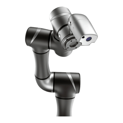
Han's Robot Elfin E03 Manual

Collaborative Robot Elfin Series
Hardware Installation
(E03/E05/E10)
V2.0.0
www.hansrobots.eu

II
Introduction
How to Use This Manual
This manual is intended for operators of Elfin robots, who should have some
electrical and programming knowledge. The manual will provide instructions for Elfin
operators from the following ways:
Safety: The operator should keep all safety instructions in mind.
Mechanical Installation: The operator should follow the instructions when
installing the robot.
Electrical interface: Open ports of Elfin are introduced for the convenience
of secondary development.
Software Control: It can guide the operator to install software and run the
robot.
Security Configuration: It introduces the basic safety settings.
Technical Support
Shenzhen Han's Robot Co., Ltd will provide you with long-term technical services. If
you have any technical problems or other needs during using our robot, you are welcome
to visit our company website: www.hansrobot.com, or directly contact our technical
engineers.
Contact Information
Company Address: 5F, Block B, Han's Innovation Mansions, No. 9018 Beihuan
Boulevard, High-tech Park, Nanshan District, Shenzhen, China
Factory Address: 4F, Building 4, Han's Laser Industrial Park, No.128 Chongqing Road,
Fuyong Town, Baoan District, Shenzhen, China
Mobile: +86 75526983668 Fax: +86 7552698278
www.hansrobots.eu

I
TABLE OF CONTENTS
INTRODUCTION...........................................................................................................II
HOW TO USE THIS MANUAL.............................................................................................II
TECHNICAL SUPPORT........................................................................................................ II
CONTACT INFORMATION...................................................................................................II
CHAPTER 1 PRODUCT INTRODUCTION...................................................................1
1.1 INTRODUCTION TO COLLABORATIVE ROBOT ELFIN SERIES.............................................1
1.2 LIST OF PARTS.........................................................................................................1
1.3 ROBOT BODY..........................................................................................................2
1.3.1 NAME OF EACH PART..................................................................................2
1.3.2 SIZE AND SPECIFICATION(E03)................................................................3
1.3.3 SIZE AND SPECIFICATION(E05)............................................................ 4
1.3.4 SIZE AND SPECIFICATION(E10)................................................................5
1.3.5 ROBOT WORKING SPACE............................................................................. 5
1.3.6 TOOL PAYLOAD RANGE................................................................................ 7
1.4 ELECTRIC CONTROL BOX...........................................................................................9
CHAPTER 2 SAFETY ISSUE...................................................................................... 11
2.1 WARNING SIGNS...................................................................................................11
2.2 GENERAL SAFETY REMINDER.................................................................................. 12
2.3 OTHER POTENTIAL RISKS........................................................................................14
2.4 RISK ASSESSMENT.................................................................................................15
2.5 STOP MECHANISM................................................................................................. 15
2.6 REPAIR AND MAINTENANCE INSTRUCTIONS..............................................................16
CHAPTER 3 MECHANICAL INSTALLATION.............................................................17
3.1 OPEN THE CARTON................................................................................................17
3.2 INSTALLATION ENVIRONMENT REQUIREMENTS..........................................................18
3.3 INSTALLATION SPACE............................................................................................. 18
www.hansrobots.eu

II
3.4 FIXING THE ROBOT(E03/E05 ROBOT).............................................................. 19
3.5 INSTALLING TOOLS TO THE TERMINAL OF ROBOT(E03/E05 ROBOT)..................... 20
3.6 FIXING THE ROBOT(E10 ROBOT)...................................................................... 21
3.7 INSTALLING TOOLS TO THE TERMINAL OF ROBOT(E10 ROBOT)............................. 22
CHAPTER 4 QUALITY WARRANTY......................................................................... 23
4.1 PRODUCT QUALITY WARRANTY.............................................................................. 23
4.2 DISCLAIMER..........................................................................................................24
CHAPTER 5 APPENDIX........................................................................................ 25
5.1 TECHNICAL SPECIFICATIONS.................................................................................... 25
5.2 LIMITING SECURITY-RELATED FUNCTIONS.................................................................31
5.3 ELECTRICAL SAFETY SPECIFICATIONS........................................................................ 31
www.hansrobots.eu

1
Chapter 1 Product Introduction
1.1 Introduction to Collaborative Robot Elfin Series
Elfin robot is a new type of human-machine collaborative six-axis robot. Its overall
design is lightweight, modular, compact and beautiful, and it can flexibly accommodate to
all kinds of complicated and varying industrial production environments.
1.2 List of Parts
Robot
Robot body
×1
End connection line
×1
Electric control box
Electric control box
×1
Power cable line
×1
Connecting cable line
×1
Teach pendant
Teach pendant
×1
Instructions
Stored in USB flash disk
×1
www.hansrobots.eu

2
1.3 Robot Body
1.3.1 Name of Each Part
Base Upper arm
Communication and power cable J5-J6 module
JI-J2 module Tool IO
Lower arm Tool flange
J3-J4 module
www.hansrobots.eu

3
1.3.2 Size and Specification(E03)
www.hansrobots.eu

4
1.3.3 Size and Specification(E05)
www.hansrobots.eu

5
1.3.4 Size and Specification(E10)
www.hansrobots.eu

6
1.3.5 Robot Working Space
The working space of robot refers to the area within the specified range around the
joint of robot base (as shown in the following table). When selecting the location to install
robot, considerations should be given to the cylinder space above and below the robot.
Please try to keep the tool away from the cylindrical space as much as possible, otherwise
it will cause the situation where the tool moves slowly and joints move too fast, which
leads to the low efficiency of robot and difficult risk assessment.
Type
E03
E05
E10
Range
590mm
800mm
1000mm
www.hansrobots.eu

7
1.3.6 Tool Payload Range
Due to different distances between load center at the end of robot and the center of
installed flange, the allowable maximum payload of robot will change accordingly. The
relationship between the centroid distance and allowable payload is shown as below:
www.hansrobots.eu

8
www.hansrobots.eu

9
1.4 Electric Control Box
Size and Specification
www.hansrobots.eu

10
Specification of electric control box:
Item
Specification
Weight
18.5Kg
Working temperature range
0~50ºC
Size
445.2*236.5*536mm
Paint color
Dark gray + white
External power input
200-240V AC,50-60Hz
www.hansrobots.eu

11
Chapter 2 Safety Issue
2.1 Warning Signs
This manual will use the following safety signs at different levels:
Danger:
Failure to follow the instructions may result in serious injury and even
death.
Warning:
Failure to follow the instructions may result in personal injury or severe
equipment damage.
Caution:
Failure to follow the instructions may result in equipment damage.
www.hansrobots.eu

12
2.2 General Safety Reminder
Some of the potentially dangerous situations are listed according to different safety
levels, and the rest of which are detailed in the chapters.
Danger:
The operator must check robot and all electrical appliances in
accordance with the instructions and warnings in Chapter 3
Mechanical Installation and Chapter 4 Electrical Ports. This operation
requires cutting power.
Warning:
Make sure that the arms and tools of the robot are installed properly
and safely.
Make sure that there is enough space for robot arms to move freely.
Make sure that safety measures (such as guardrails, ropes, or
protective screens) are taken near the robot operation area to protect
the operator and surrounding people.
Don’t wear loose clothes or jewels when operating the robot. Please be
sure to tie your long hairs up and keep them behind your head when
operating the robot.
Don’t use the robot if it is damaged.
If the software gives out a fatal error message, please activate the
emergency stop quickly, write down the situation that causes the error,
find out the related error codes on the code page, and contact us.
Don’t connect the safety device to the normal I/O port. Only secure
port can be used.
Make sure right installation configuration (such as robot’s installation
angle, weight in TCP, TCP offset, safety setting), and save the
installation file and load it into the program.
Free drive function (impedance / reverse drive) can only be used in the
installation process after passing the risk assessment. Tools and
obstacles should not have sharp corners or twists. Please ensure that
the head and face of people are beyond the reach of robot.
www.hansrobots.eu

13
Pay attention to the movement of robot when using Teach Pendant.
Don’t enter the safety scope of the robot or touch the robot when the
system is running.
Any collision will release a large amount of kinetic energy, which is
much stronger than the kinetic energy of high-speed and overloading
operations.
Connecting different machines may pose risks or cause new danger. A
comprehensive risk assessment on the whole installation process
should always be carried out. When different safety and emergency
stop performance levels are required, the highest performance level
should always be selected. Always read and understand the user
manual of all the devices used in the installation.
Don’t modify the robot. Any modification of the robot could cause the
unpredictable danger for integrators. The authorized reconfiguration of
robot should be in accordance with the latest edition of all related
service manuals. If the robot is changed or altered in any way, we
refuse to take any responsibility.
Robot and electric control box will produce heat in the operating
process. The robot can cool down after cutting off the power and
waiting for an hour.
Caution:
When the robot is connected or work together with other machines that
may damage the robot, it is strongly recommended that all functions of
the robot and robot program shall be checked separately. It is
recommended to use other temporary road points outside the
mechanical workspace to detect the robot program.
Prevent the robot from being exposed to permanent magnetic fields. A
strong magnetic field can damage the robot.
www.hansrobots.eu

14
2.3 Other Potential Risks
Please note that certain robot devices may have other major risks:
Fingers are clamped between the robot foot and base.
Fingers are clamped between the two arms.
Sharp edges and sharp points on the tool or tool connector stab people’s
skin.
Sharp edges and sharp points on the obstacle near the robot trail stab
people’s skin.
People get hurt after being hit by the robot.
A sprain or fracture caused by the impact of robot’s payload on solid
surface.
The consequences of loosening bolts on fixed robot arm or tool.
An item falls from the tool because of improper clamping or power off.
An operation error caused by different e-stop buttons on different
machines.
www.hansrobots.eu

15
2.4 Risk Assessment
Risk assessment is one of the most important tasks that the integrator must
complete. Robot itself is a partially completed machine, and the safety of installed robot
depends on how the robot is integrated (such as tool, obstacle and other machinery).
It is recommended that the integrator should use the guidelines of ISO12100 and
ISO10218-2 to carry out risk assessment.
The risk assessment needs to consider two situations: the risk of robot installation,
robot demonstration and the risk of running robot.
For the non-collaborative installation of robot (e.g. when using dangerous tools), risk
assessment may infer that integrators need to connect additional security devices (such as
activating device) to protect themselves when programming.
2.5 Stop mechanism
All the moving parts of robot will stop when the e-stop is activated. After releasing
the e-stop, no action of the robot is started. E-stop cannot be used as a risk reduction
measure, but it can be used as a secondary protection device. If multiple e-stop buttons
need to be connected, they should be included in the risk assessment of robot
application.
www.hansrobots.eu

16
2.6 Repair and Maintenance Instructions
All the safety instructions in this manual must be strictly observed when performing
maintenance and maintenance work.
Danger:
Remove the main input cable from the bottom of electrical box
to ensure it is completely power down; Disconnect other energy
sources connected to the robot arm or electrical control box, and
take the necessary precautions to prevent others from
reconnecting the system energy during the maintenance.
The grounding lines must be checked before restarting the
system.
Don’t dismantle the power supply system of electric control
box. The power supply system may retain high voltage (up to
600V) after the electric control box is turned off.
Keep robot arm or electric control box away from water or
dust.
After maintenance, it must be checked to ensure that is meets
the service requirements and safety level. It is necessary to
observe effective national or local safety laws and regulations.
Meanwhile, all safety functions should be checked.
www.hansrobots.eu
This manual suits for next models
2
Table of contents
Other Han's Robot Robotics manuals
Popular Robotics manuals by other brands
Omron Adept MobileRobots
Omron Adept MobileRobots Pioneer 3 Operation manual

Mitsubishi Electric
Mitsubishi Electric RP-1ADH-S15 Series Standard Specifications Manual

Thames & Kosmos
Thames & Kosmos SolarBots Experiment manual

ABB
ABB IRB 6650S - 200/3.0 product manual
Segway Robotics
Segway Robotics RMP 440 Omni V3 user manual
Sony
Sony ERS-7M3 User Guide (PC Network) user guide
