Pololu 3pi+ 32U4 User manual

Pololu 3pi+ 32U4 User’s uide
Pololu 3pi+ 32U4 User’s uide © 2001–2022 Pololu Corporation
https://www.pololu.com/docs/0J83/all Page 1 of 86

1. Overview . . . . . . . . . . . . . . . . . . . . . . . . . . . . . . . . . . . . . . . . . . . . . . 3
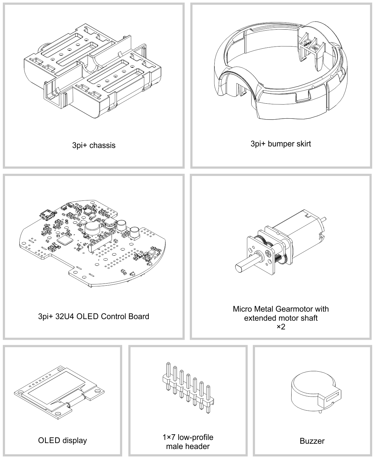
1.1. Configurations and included components . . . . . . . . . . . . . . . . . . . . . . . . . . 6
1.2. What you will need . . . . . . . . . . . . . . . . . . . . . . . . . . . . . . . . . . . . 13
1.3. Supported operating systems . . . . . . . . . . . . . . . . . . . . . . . . . . . . . . . 14
2. Contacting Pololu . . . . . . . . . . . . . . . . . . . . . . . . . . . . . . . . . . . . . . . . . 15
3. Assembling the 3pi+ 32U4 kit . . . . . . . . . . . . . . . . . . . . . . . . . . . . . . . . . . 16
4. Using the preloaded demo program . . . . . . . . . . . . . . . . . . . . . . . . . . . . . . . 37
5. The 3pi+ 32U4 in detail . . . . . . . . . . . . . . . . . . . . . . . . . . . . . . . . . . . . . . 40
5.1. Microcontroller . . . . . . . . . . . . . . . . . . . . . . . . . . . . . . . . . . . . . . . 41
5.2. User interface . . . . . . . . . . . . . . . . . . . . . . . . . . . . . . . . . . . . . . . 42
5.3. Motors . . . . . . . . . . . . . . . . . . . . . . . . . . . . . . . . . . . . . . . . . . . 44
5.4. Quadrature encoders . . . . . . . . . . . . . . . . . . . . . . . . . . . . . . . . . . . 46
5.5. Line and bump sensors . . . . . . . . . . . . . . . . . . . . . . . . . . . . . . . . . . 48
5.6. Inertial sensors . . . . . . . . . . . . . . . . . . . . . . . . . . . . . . . . . . . . . . 50
5.7. Power . . . . . . . . . . . . . . . . . . . . . . . . . . . . . . . . . . . . . . . . . . . 51
5.8. Expansion headers . . . . . . . . . . . . . . . . . . . . . . . . . . . . . . . . . . . . 55
5.9. Pin assignments . . . . . . . . . . . . . . . . . . . . . . . . . . . . . . . . . . . . . . 57
5.10. Adding electronics . . . . . . . . . . . . . . . . . . . . . . . . . . . . . . . . . . . . 61
5.11. AVR timers . . . . . . . . . . . . . . . . . . . . . . . . . . . . . . . . . . . . . . . . 63
5.12. Schematics and dimensions . . . . . . . . . . . . . . . . . . . . . . . . . . . . . . . 63
6. Programming the 3pi+ 32U4 . . . . . . . . . . . . . . . . . . . . . . . . . . . . . . . . . . . 65
6.1. Installing Windows drivers . . . . . . . . . . . . . . . . . . . . . . . . . . . . . . . . . 65
6.2. Programming using the Arduino IDE . . . . . . . . . . . . . . . . . . . . . . . . . . . 67
6.3. Programming using avr-gcc and AVRDUDE . . . . . . . . . . . . . . . . . . . . . . . 72
7. Pololu3piPlus32U4 Arduino library . . . . . . . . . . . . . . . . . . . . . . . . . . . . . . . . 75
8. The 3pi+ 32U4 USB interface . . . . . . . . . . . . . . . . . . . . . . . . . . . . . . . . . . 76
9. The A-Star 32U4 Bootloader . . . . . . . . . . . . . . . . . . . . . . . . . . . . . . . . . . . 78
10. Reviving an unresponsive 3pi+ 32U4 . . . . . . . . . . . . . . . . . . . . . . . . . . . . . . 81
10.1. Reviving using the Arduino IDE . . . . . . . . . . . . . . . . . . . . . . . . . . . . . 81
10.2. Reviving using AVRDUDE . . . . . . . . . . . . . . . . . . . . . . . . . . . . . . . . 84
11. Related resources . . . . . . . . . . . . . . . . . . . . . . . . . . . . . . . . . . . . . . . . 85
Pololu 3pi+ 32U4 User’s uide © 2001–2022 Pololu Corporation
Page 2 of 86

1. Overview
The 3pi+ 32U4 is a versatile, high-performance, user-programmable robot that measures just 9.7 cm
(3.8″) in diameter. At its heart is an ATmega32U4 AVR microcontroller from Microchip (formerly
Atmel), and like our A-Star 32U4 programmable controllers [https://www.pololu.com/category/149/a-
star-programmable-controllers], the 3pi+ 32U4 features a USB interface and ships preloaded with an
Arduino-compatible bootloader, so all you need to program it is a USB A to Micro-B cable
[https://www.pololu.com/product/2072] (not included). A software add-on is available that makes it easy to
program the robot from the Arduino environment, and we have Arduino libraries and example sketches
to help get you started. For advanced users who want to customize or enhance their robots with
additional peripherals, the robot’s power rails, power system controls, and microcontroller’s I/O lines
can be accessed via several 0.1″-pitch expansion ports.
3pi+ 32U4 OLED Robot,
front view.
3pi+ 32U4 OLED Robot,
side view.
3pi+ 32U4 OLED Robot,
rear view.
The 3pi+ (or 3𝜋+) features two H-bridge motor drivers and a variety of integrated sensors, including
a pair of quadrature encoders for closed-loop motor control, a complete inertial measurement unit
(3-axis accelerometer, gyro, and magnetometer), five downward-facing reflectance sensors for line-
following or edge-detection, and left and right bump sensors along the front face of the robot. Three on-
board pushbuttons offer a convenient interface for user input, and a 128×64 graphical OLED display
(LCD on original version), buzzer, and indicator LEDs allow the robot to provide feedback.
Pololu 3pi+ 32U4 User’s uide © 2001–2022 Pololu Corporation
1. Overview Page 3 of 86

The robot also features a unique power system that runs the motors at a constant 8 V independent of
the battery charge level, so the speed of the motors does not vary with the battery voltage.
3pi+ 32U4 versions
The original version of the 3pi+ 32U4 includes an 8×2 character LCD [https://www.pololu.com/product/
356], while the newer 3pi+ 32U4 OLED incorporates a graphical OLED display [https://www.pololu.com/
product/3760] instead. The information in this user’s guide generally applies to both versions, and
the name “3pi+ 32U4” covers both the original (LCD) and OLED versions except where specific
differences are noted.
Our Pololu3piPlus32U4 Arduino library [https://www.pololu.com/docs/0J83/7] generally allows code
written for the LCD version to work on the OLED version with minimal changes (and the reverse is
also true as long as your code does not make use of the OLED’s graphical capabilities).
Pololu 3pi+ 32U4 User’s uide © 2001–2022 Pololu Corporation
1. Overview Page 5 of 86

3pi+ 32U4 Robot, top view. 3pi+ 32U4 OLED Robot, top view.
Comparison with the original 3pi
The 3pi+ 32U4 offers many major improvements over the original 3pi [https://www.pololu.com/product/
975], including:
• ATmega32U4 microcontroller with Arduino-compatible bootloader can be programmed
directly through a USB connection
• Quadrature encoders on both motors for closed-loop position and speed control
• raphical OLED display (OLED version only)
• Full 9-axis IMU (three-axis gyro, accelerometer, and compass)
• Bottom-loading battery holders keep batteries accessible even if additional levels are added
• Full wrap-around bumper to protect electronics from collisions
• Two bump sensors on the front
The 3pi+ 32U4 uses a different microcontroller with different pin mappings compared to the older 3pi,
and some of the software library interfaces are different, so programs written for the original 3pi will
not work on the 3pi+ 32U4 without modification.
1.1. Configurations and included components
The 3pi+ 32U4 OLED robot is available as a kit or fully assembled with three different motor options:
Pololu 3pi+ 32U4 User’s uide © 2001–2022 Pololu Corporation
1. Overview Page 6 of 86

3pi+ 32U4
OLED
Version
Products
Micro
Metal
earmotor
Top
Speed Comments
Standard
Edition
assembled
or kit 30:1 MP 6V 1.5 m/
sgood combination of speed and controllability
Turtle
Edition
assembled
or kit 75:1 LP 6V 0.4 m/
s
longest battery life, easiest to control, good for
swarm robots or introductory robotics courses
Hyper
Edition
assembled
or kit
15:1 HPCB
6V
~4 m/
s
very fast and difficult to control, easy to
damage; only recommended for advanced
users
In addition, the 3pi+ chassis [https://www.pololu.com/product/3725] and 3pi+ 32U4 OLED control board
[https://www.pololu.com/product/4974] are available separately and can be combined with the motors
[https://www.pololu.com/category/141/micro-metal-gearmotors-with-extended-motor-shafts] of your choice to
make a custom kit.
The original (LCD) version of the 3pi+ 32U4 robot is also available in these three editions—Standard
(assembled [https://www.pololu.com/product/3737] or kit [https://www.pololu.com/product/3740]), Turtle
(assembled [https://www.pololu.com/product/3738] or kit [https://www.pololu.com/product/3741]), and Hyper
(assembled [https://www.pololu.com/product/3736] or kit [https://www.pololu.com/product/3739])—and as a
separate control board [https://www.pololu.com/product/3735].
3pi+ 32U4 robot kit contents
Pololu 3pi+ 32U4 User’s uide © 2001–2022 Pololu Corporation
1. Overview Page 7 of 86

The kit versions of the 3pi+ 32U4 OLED robot include the following items:
•3pi+ Chassis Kit [https://www.pololu.com/product/3725], which includes:
◦ 3pi+ chassis, with integrated 4×AAA battery holder and ball caster
◦ 3pi+ bumper skirt
◦ two 3pi+ motor clips
◦ two 32×7 mm Pololu wheel hubs and silicone tires
◦ four single AAA battery contacts
◦ two double AAA battery contacts
◦ 1/2″-diameter plastic ball
•3pi+ 32U4 OLED Control Board [https://www.pololu.com/product/4973], which includes:
◦ control board
◦buzzer [https://www.pololu.com/product/1484]
◦ jumper wires (for soldering motors to the main board)
◦ 1×7 low-profile male header for OLED display (original version kits include an 2×7
Pololu 3pi+ 32U4 User’s uide © 2001–2022 Pololu Corporation
1. Overview Page 8 of 86

low-profile male header [http ://www.pololu.com/product/2663] for the LCD instead)
◦ two magnetic encoder discs [https://www.pololu.com/product/2599] (12 CPR)
◦ four 3/16″ #2-56 screws [https://www.pololu.com/product/2701] and nuts
[https://www.pololu.com/product/1067]
◦ two 1/4″ #2-56 standoffs [https://www.pololu.com/product/1940] (OLED version only)
• two Micro Metal earmotors [https://www.pololu.com/category/141/micro-metal-gearmotors-with-
extended-motor-shafts] (the table above lists the specific motors included with each edition)
•graphical OLED display [https://www.pololu.com/product/3760] (original version kits include an
8×2 character LCD [http ://www.pololu.com/product/356] instead)
• spare 15:1 gearbox (Hyper Edition only)
Pololu 3pi+ 32U4 User’s uide © 2001–2022 Pololu Corporation
1. Overview Page 9 of 86

The diagrams above show the contents of the 3pi+ 32U4 OLED kits. For the contents of
the original 3pi+ 32U4 kits, which include an LCD and differ in a few other parts, refer to
these diagrams instead.
The robot and chassis kit might include extra parts like jumper wires, screws, and nuts,
so do not be concerned if you have some leftover hardware after assembling your 3pi+.
Assembled 3pi+ 32U4 robot
The assembled versions of the 3pi+ 32U4 robot are complete, ready-to-program robot platforms built
from the same components found in the 3pi+ 32U4 robot kits; no soldering or assembly is required.
Pololu 3pi+ 32U4 User’s uide © 2001–2022 Pololu Corporation
1. Overview Page 12 of 86

1.2. What you will need
These additional items are needed for using the 3pi+ 32U4 robot:
• four AAA batteries—the robot works with both alkaline and NiMH batteries, though we
recommend using rechargeable AAA NiMH cells [https://www.pololu.com/product/1002]
•USB A to Micro-B cable [https://www.pololu.com/product/2072] to connect the robot to your
computer for programming and debugging
• small 2 mm slotted screwdriver for adjusting the LCD contrast (original LCD version only)
Kit assembly tools
These additional items are needed or helpful for assembling the 3pi+ 32U4 robot kit:
• soldering iron and solder (we recommend one with adjustable temperature control)
• wire cutter
• small #1 Phillips screwdriver
Pololu 3pi+ 32U4 User’s uide © 2001–2022 Pololu Corporation
1. Overview Page 13 of 86

• flush cutter, knife, and/or file for cutting supports on the bumper skirt (optional but
recommended)
• Tape or small clamps (for holding parts together when soldering)
Additional optional components
You might also consider getting these for your 3pi+ 32U4 robot:
•Sensors [https://www.pololu.com/category/7/sensors], such as proximity sensors or range
finders [https://www.pololu.com/category/189/proximity-sensors-and-range-finders]
•Connectors and jumper wires [https://www.pololu.com/category/19/connectors], for connecting
additional sensors and components
• Battery charger, if you are using rechargeable batteries; since the 3pi+ just uses ordinary
AAA batteries, we recommend basic AAA chargers (into which you stick the individual cells)
available at most general electronics stores, though we carry a much fancier iMAX-B6AC V2
balance charger/discharger [https://www.pololu.com/product/2588] that can be also used for this
1.3. Supported operating systems
The 3pi+ 32U4 can be programmed using current versions of Microsoft Windows 11, Windows 10,
Linux, and macOS. See our A-Star 32U4 bootloader page on itHub [https://github.com/pololu/a-star/
tree/master/bootloaders/caterina] for a list of older operating systems that have been tested with the
bootloader and are likely to work.
Pololu 3pi+ 32U4 User’s uide © 2001–2022 Pololu Corporation
1. Overview Page 14 of 86

2. Contacting Pololu
We would be delighted to hear from you about any of your projects and about your experience
with the 3pi+ 32U4. You can contact us [https://www.pololu.com/contact] directly or post on our forum
[http://forum.pololu.com/]. Tell us what we did well, what we could improve, what you would like to see in
the future, or anything else you would like to say!
Pololu 3pi+ 32U4 User’s uide © 2001–2022 Pololu Corporation
2. Contacting Pololu Page 15 of 86

3. Assembling the 3pi+ 32U4 kit
This section explains how to assemble the kit version of the 3pi+ 32U4 robot. If you have the pre-
assembled version, you can skip to Section 4.
See Section 1.1 for a diagram to help you identify the contents of the 3pi+ 32U4 robot
kit.
<div class="player-unavailable"><h1 class="message">An error occurred.</h1><div class="submessage"><a
Testing the control board before assembly
1. Before beginning assembly, plug the 3pi+ 32U4 control board in to USB and verify that it
works by observing the behavior of its LEDs. You should see the yellow, green, and red
user LEDs light briefly and turn off, and then the green user LED should start blinking slowly.
Disconnect the control board after you confirm it is working.
Battery contacts
2. Insert the two double battery contacts into the bottom of the chassis as shown, making sure
to put them on the correct side.
Pololu 3pi+ 32U4 User’s uide © 2001–2022 Pololu Corporation
3. Assembling the 3pi+ 32U4 kit Page 16 of 86

Motors and encoders
4. After installing the tires on the wheels, press the output shaft of each motor into a wheel, with
the flat side of the wheel hub facing the motor. The end of the gearbox shaft should end up
flush with the outside of the wheel. A good way to do this is to set the wheel on a flat surface
(like a table top) and press the motor shaft into the wheel until it contacts the surface.
Pololu 3pi+ 32U4 User’s uide © 2001–2022 Pololu Corporation
3. Assembling the 3pi+ 32U4 kit Page 18 of 86

5. Cut two of the included jumper wires in half to form four segments, and trim off the ends
that are covered in adhesive (the adhesive could interfere with making a good electrical
connection to the motor). These wire segments will be used as motor leads.
6. Solder a pair of leads to each motor, paying attention to the way the motor will eventually be
oriented in the chassis (see below). You might find it helpful to make a small bend at the tip
of each lead to hook into the hole in the motor lead tab to hold it in place for soldering.
Pololu 3pi+ 32U4 User’s uide © 2001–2022 Pololu Corporation
3. Assembling the 3pi+ 32U4 kit Page 19 of 86

Warning: Holding the soldering iron against the motor lead for more than a few seconds can
start to damage the motor brushes, so try to be reasonably quick/efficient with this soldering.
If the first attempt does not go well, remove the soldering iron and let the motor cool for a
few seconds before trying again.
Each motor’s positive terminal is indicated by a plus sign (+) in the black plastic end of the motor.
For consistency, we recommend soldering the motors to the control board with the positive terminal
closest to the front, so you should attach the leads to allow the motors to be oriented this way. (Don’t
worry if you accidentally get the orientation of one or both motors wrong, though. You can later correct
for it in software with our Pololu3piPlus32U4 library.)
7. Press a magnetic encoder disc onto the motor shaft of each motor so that the end of the shaft
is flush with the back of the disc. One easy way to accomplish this is to press the motor onto
the disc while the disc is sitting on a flat surface, pushing until the shaft makes contact with
that surface.
Pololu 3pi+ 32U4 User’s uide © 2001–2022 Pololu Corporation
3. Assembling the 3pi+ 32U4 kit Page 20 of 86
Other manuals for 3pi+ 32U4
1
Table of contents
Other Pololu Robotics manuals