3
Contents
Introduction
Caution
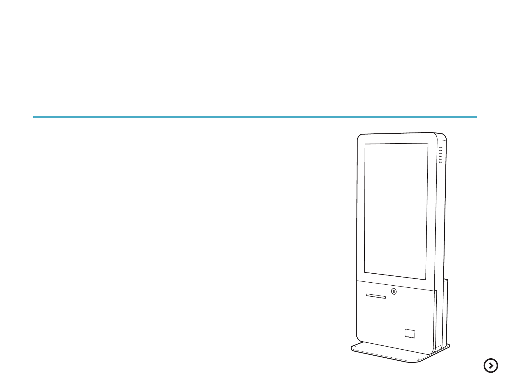
Introduction
Specification&Options
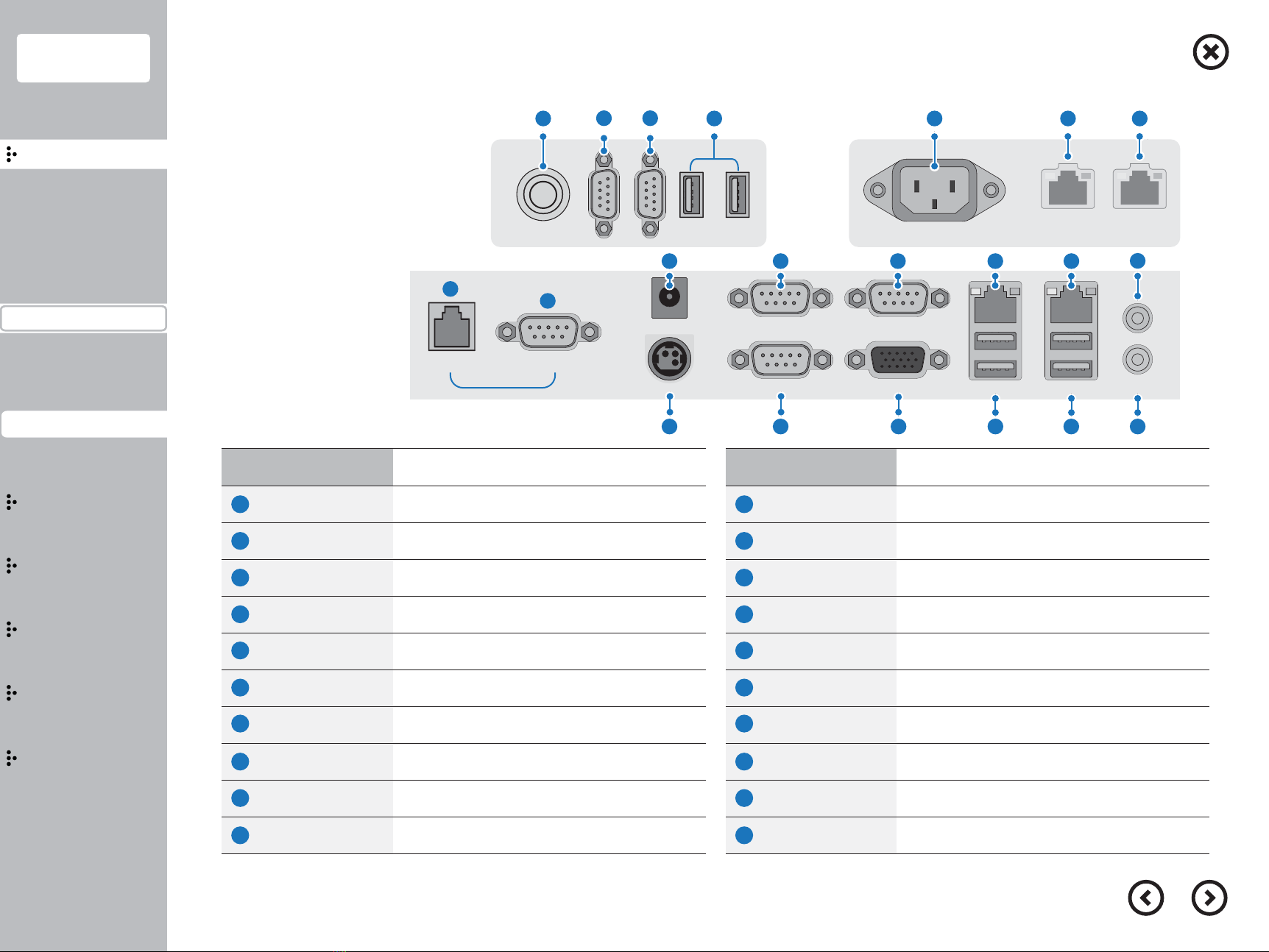
Part name&Function
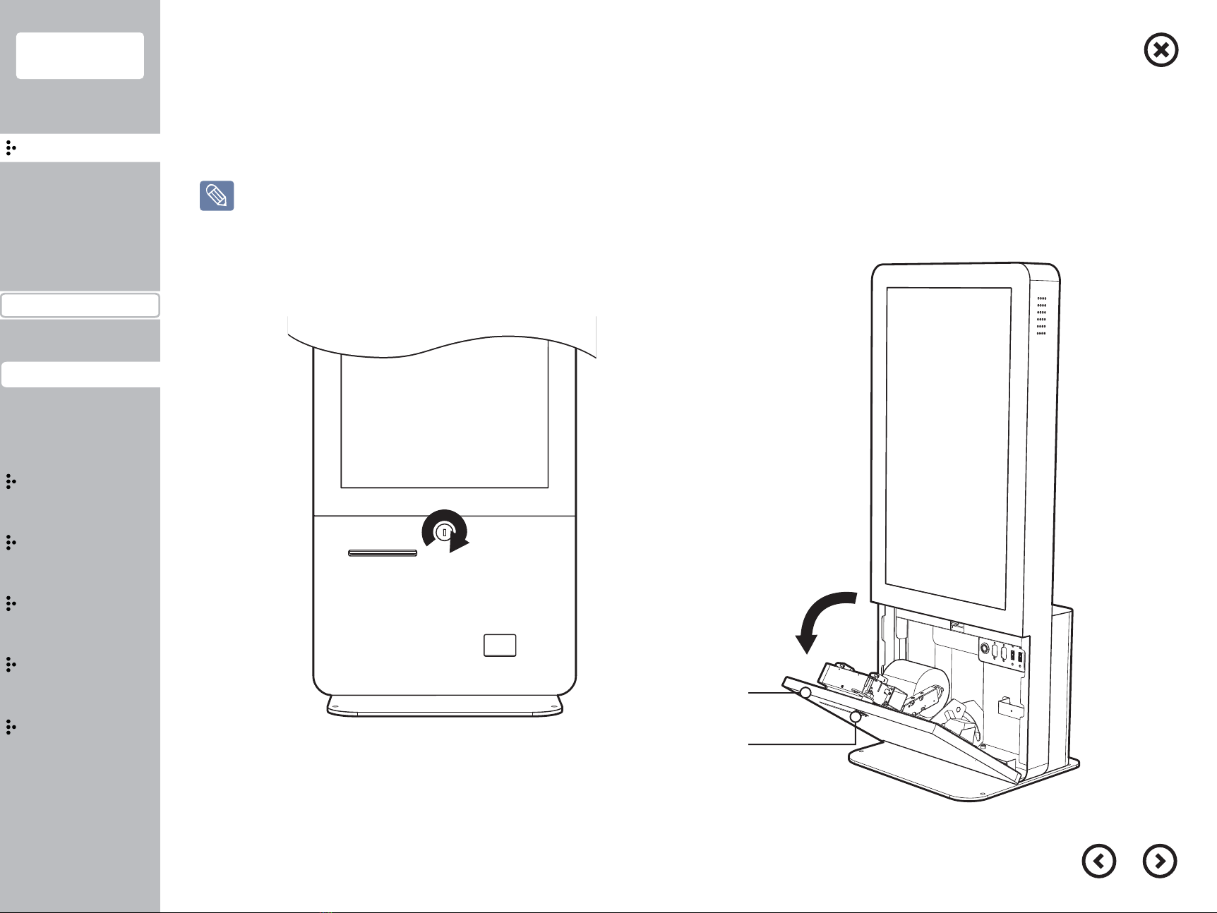
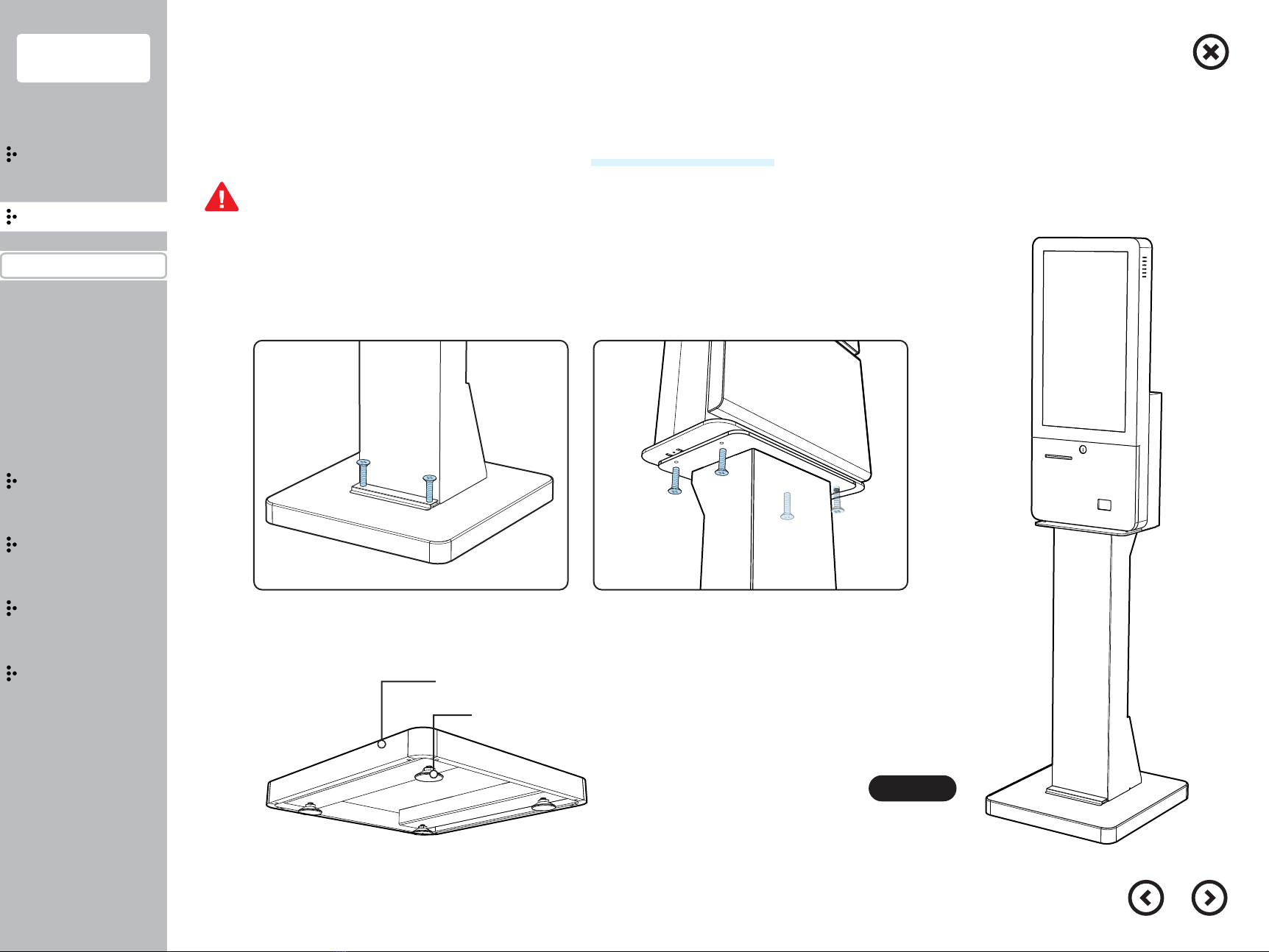
Installation
Usage
Extension
Bios
Configuration
Precautions
Safety precautions
Please read the manual carefully to prevent any damage and injury then use the product properly.
When you install the product, please put the product on the stable table.
When you put the product on the table, do not put the product on the steep table and waving area.
Please do not put any rug and blanket having static electricity.
It can cause HDD/SSD data removal and any circuit damage.
Please use the product in the wide area having ventilation.
Please avoid direct sun-ray, humid area, hot and frequent temperature change area.
Do not connect the product with high power consumption electronic product.
Please use the power plug having proper purpose and power capacity.
Please do not install the product nearby wireless electronic devices.
Please use the power adaptor and plug provided and certified from the supplier.
Please turn off the power when you try to disassemble the product.
Please do not try to disassemble the product except the guideline as it indicated, it can cause the defec-tor and problem.
Please back up your data frequently, supplier can not guarantee the data removal.
■