Hanbell RC2-100 Installation manual

HANBELL COMPRESSOR
INSTALLATION & START-UPGUIDE
RC2-100 TORC2-930
Rev M.5.2
WARNING!
NO OIL is shipped in compressor.
Compressor must NEVER be run backwards.
These Safeties ARE Required at Startup to Maintain Hanbell Warranty
a)
Motor Module Trip (INT69HBY): Open for 1 second
b)
Low Oil Level Float Trip: Open for 30-60 seconds
c)
Unsafe Suction: Less than 5 psi for 3 seconds
d)
Low Differential Pressure: Less than 65 psi for 60 seconds (Oil Psi – SuctionPsi)
e)
Unsafe Differential Pressure: Less than 35 psi for 5 seconds (Oil Psi – SuctionPsi)
f)
Low Discharge Superheat: Less than 25°F for 300 seconds Revision –10/02/19

COMPRESSOR INSTALLATION & START-UP GUIDE
REVISION M
2
The MCS Commitment: Our commitment is to provide practical solutions for the industry’s needs and to be both a
leader and a partner in the effective use of microprocessor controls.
Micro Control Systems, Inc.
5580 Enterprise Parkway Fort
Myers, Florida 33905 Phone:
(239) 694-0089
Fax: (239) 694-0031
www.MCScontrols.com
(Website contains product descriptions, manuals, software releases and troubleshooting aids among others)
All information contained within this document is considered to be proprietary information of Micro Control Systems, Inc. No
information or data from this document shall be published, used, reproduced, transmitted, or disclosed to others outside your
organization without the prior expressed written consent of Micro Control Systems, Inc. This document and the information
contained herein shall be treated as proprietary. Reasonable provisions shall be provided to ensure that this information
remains proprietary by your employees, agents and other personnel that may have access to this document.
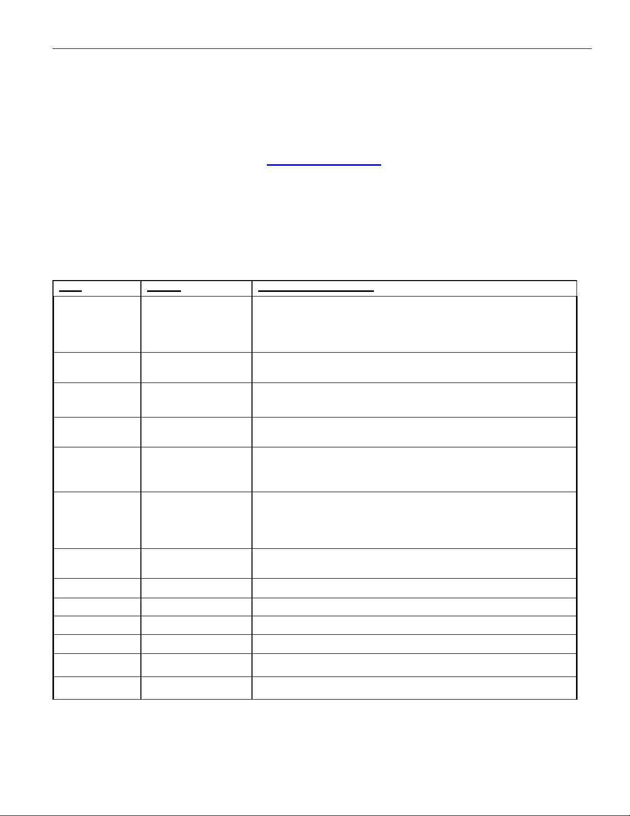
Revision:
Date
Author
Description of Changes
12/03/12 M. Schreiber / X. Beltran
Update Manual to REV H
Updated Hanbell Liquid Injection Piping
ATTENTION: Step Control Loading Plate Design In RC2Series
Added Revision Chart
Updated / Added Solenoid Installation & AlignmentPictures
12/06/12 M. Schreiber Update Manual to REV I
Added Hanbell Compressor Picture
05/24/13
M. Schreiber
Update Manual to REV J
Updated Hanbell Liquid Injection Piping
Added Hanbell Flooded Type Compressor with Oil Separator
06/13/13 M. Schreiber Update Manual to REV K
Updated Hanbell Liquid Injection Piping
6/18/13 K. Mitchell
Update Manual to Rev L
Updated wiring of electrical power terminals
Added rotation of compressor
Inserted Tableof Contents
11/04/14 X. Beltran
Update Manual to Rev M
Updated Installation Procedures (Liquid InjectionSolenoid)
Updated INT69HBY diagnose wiringdiagram
Updated Hanbell Flooded Typediagrams
Updated images Hanbell VFD &Solenoids
7/30/15 DEW Update Manual to Rev N
Update page 11
8/27/15
DEW
Update section 13
11-16-16
DEW
Replace dwg pg 6, 7,9, 212. 22
04-18-17
DEW
Add Warranty Maintenance Info in back
11-27-17
DEW
Edits to pages 11,12,13 picked up from App097
12-28-17
DEW add POE OIL Warning
09-05-17
DEW Add Note on Economizer, Drawing

COMPRESSOR INSTALLATION & START-UP GUIDE
REVISION M
3
Table of Contents
Compressor Crate Unpacking & Inspection.......................................................................................................4
Compressor Safety Instructions.........................................................................................................................5
Installation Procedures......................................................................................................................................5
Recommended Liquid Injection Piping...............................................................................................................6
Screw Compressor Wiring Procedures..............................................................................................................7
INT69HBY.......................................................................................................................................................12
Maintenance Area Requirement ......................................................................................................................18
Compressor Piping..........................................................................................................................................20
Electrical Wiring...............................................................................................................................................20
Pre-Start-up Procedure....................................................................................................................................21
Start-up Procedure..........................................................................................................................................25
Recommended Safety Settings .......................................................................................................................25
Hanbell with VFD.............................................................................................................................................26
Solenoids ........................................................................................................................................................27
Slide Amp Calculation......................................................................................................................................34
Handling POE Oil Information..........................................................................................................................39
Warranty / Maintenance Information................................................................................................................40

COMPRESSOR INSTALLATION & START-UP GUIDE
REVISION M
4
1.
Compressor Crate Unpacking & Inspection
1.1.
Inspect crate and compressor for anyshipping
damage.
1.2.
The compressor is in an easy open crate, cutstraps
and lift off crate top from base.
1.3.
Use either steel cable or safety ropes to lift the
compressor, see Figure 1. The cable shouldbe
capable of holding up to a minimum of 2 tons.
Use caution while lifting the compressor
Figure 1
Lifting Compressor with Steel Cable
⇒Make sure that the steel cable does not touch the Solenoid Valves, Capillary, Oil Heater, Discharge
Temperature Sensor and or Power Terminals, etc. to prevent damage.
⇒Use only steel cable or safety ropes to lift the compressor; make sure that the cable/rope has the
proper strength to lift the compressor.
⇒Keep the compressor horizontal while lifting.
1.4.
Check compressor nameplate for correct model and voltage designation.
1.5.
To facilitate customer installation requirements, the parts listed in Table 1 are factory supplied in separate boxes
located in the compressor terminal box or packed in the compressor shipping container. Please verify that you
have received all accessory parts.
Table 1: Compressor Accessories & Service Valve Parts
Qty
Description
1
Stop Valve Assembly
1 stop valve, 2 gaskets, 1 charging valve, 4 bolts, 1 half union connector, 1 flare nut, 1 flare seal
bonnet
1
Discharge bushing connector
1
Suction bushing connector
1
Motor Terminal Junction Box Assembly
1 terminal box, 1 motor protection, 2 plastic terminal plugs, 1 reset button, 4 wires
(refer to Figure 4-B)

COMPRESSOR INSTALLATION & START-UP GUIDE
REVISION M
5
2.
Compressor Safety Instructions
2.1.
Follow recognized safety procedures and practices.
2.2.
In order to prevent the penetration of moisture, air or impurities, the compressor has been charged with Nitrogen
gas. Do not remove any compressor bolts or fittings until the factory supplied holding charge has been relieved
2.3.
Do not apply any power to the compressor unless all valves are open and solenoids are energized (suction /
discharge, service valves, economizer and oil shut off valves).
2.4.
Do not operate or provide any electrical power to the compressor unless the terminal box cover is in place and
secured. Measurements of the current and voltage during running conditions must be taken at other points in the
power supply.
2.5.
Do not remove terminal box cover until all electrical sources have been disconnected.
WARNING: Failure to follow these instructions could result in serious personal injury.
3.
Installation Procedures
3.1.
Holding Charge: The screw compressor is factory supplied with 7 psig (0.5 bar) holding charge of nitrogen gas.
The internal pressure must be relieved before attempting to remove any compressor fittings or parts. Relieve the
holding charge by removing the threaded cap on the low pressure Schrader connection fitting and depressing
the internal Schrader stem.
CAUTION: This compressor may contain trace amounts of oil. Do not relieve the holding
charge or open the compressor pots until it is ready to be connected to a closed dry system.
Excessive moisture may shorten compressor life.
3.2.
Installation of the Compressor Electrical Terminal Box: Four bolts located on the top of the electrical terminal
box cover mount the electrical terminal box; it is adjustable to the cable hole direction to meet the power cables’
optional connection direction from the chiller.
3.3.
Oils: Adding and removing oil is done through the Drain valve located on the solenoid side of compressor. The
compressor has no oil and is not charged with oil. When adding or doing a complete change, use only the
listed Hanbell approved oils. POE oils readily absorb moisture and cause acid formation in the system.
Keep oil exposure to the atmosphere to a minimum.
3.4.
Installation of the Service/Stop Valve: Unpack the service/stop valve’s box then check against the list on the
outside of the box to ensure correct parts. Be sure that all parts inside the carton are clean. Use the four bolts to
secure the service/stop valve. Use PTFE sealer to seal the adapter while tightening it. Please refer to Figure 5-A
for space requirements for future service and maintenanceneeds.
3.5.
Service/stop Valve Recommended Connection
Figure 3-A RC2-100, 140& 180 Figure 3-B RC2-170, 200~580 & 620 Figure 3-C RC2-610, 710~930

COMPRESSOR INSTALLATION & START-UP GUIDE
REVISION M
6
3.6.
Liquid Injection Solenoid Valve and Expansion Valve (Required, Not included with compressor): The
liquid injection system may be piped, but it is necessary to consider the required space for adjustment of the
expansion valve while testing or running the compressor. Please refer to installation guide in the following
section for connection points.
3.7.
PTC Discharge Temperature Protection: Each compressor comes standard with three PTC sensors in the
motor windings and one located at the discharge port. A motor module (INT69HBY) is installed in the electrical
terminal box. Refer to Figure 4-B showing the connection of motor and discharge PTCs in series to the motor
module corresponding terminal blocks.
4.
Recommended Liquid Injection Piping
Note A: It is necessary to adjust the Ball Valve to feed small amounts of liquid (drops) to the
compressor motor.

COMPRESSOR INSTALLATION & START-UP GUIDE
REVISION M
7
5.
Screw Compressor Wiring Procedures
Following the diagrams below will prevent damage to the electrical terminals and the
possibility of personal injury.

COMPRESSOR INSTALLATION & START-UP GUIDE
REVISION M
8
Terminal
V2
The method to tell the terminals (V-Phase)
1. By alphabet: Refer to the alphabet beside each terminal bolt in a star-delta motor.
2. By numbers: Refer to the number beside each bolt in a PWS motor.

COMPRESSOR INSTALLATION & START-UP GUIDE
REVISION M
9
Figure 5-A Motor Wiring

COMPRESSOR INSTALLATION & START-UP GUIDE
REVISION M
10
5.1.
Electrical Power Terminals
The power terminals of Hanbell compressors are made from ceramic materials and well insulated
more than 1000MΩ. Be careful connecting the wiring and follow the list below.
⇒The ceramic part on the power terminal should not be tighten by hitting otherwise the insulation of
the power terminal could be degraded.
⇒Follow the drawing shown below for the wiring to prevent the power terminal from being damaged.
⇒The setting of the torque wrench for tightening the copper nut of the terminal bolts should be set less
than 500 kg-cm (36 pound/inch)
The insulation of the ceramic power terminals are very easily degraded by water, so DO NOT take
the leakage test by immersing the whole compressor in the water. Shut down the chiller first for
service if the insulation valve of the power terminal is lower than 5MΩ.

COMPRESSOR INSTALLATION & START-UP GUIDE
REVISION M
11
5.2.
Across the Line Jumper Bar Installation
Photo shows extra nuts installed under jumper bar for
clearance of power bolt Insulation.
Connect line voltage directly on Terminal post.

COMPRESSOR INSTALLATION & START-UP GUIDE
REVISION M
12
6.
Description - INT69HBY DIAGNOSE
Hanbell supplies INT69 HBY Diagnose for motor protection with monitoring functions of phase loss, phase
sequence, motor temperature, and discharge temperature. The module has built in flash codes that are help-
ful for diagnosing safety faults.
In order to protect the compressor, each RC2 series compressor has been built with three PTCtemperature
sensors inside the motor coil and one at the discharge port neck of the compressor. These sensors are con-
nected to the motor module to monitor coil temperature and discharge temperature. Up to 9 sensors can be
connected in series and used with one module.
If the temperature in one of the positions monitored exceeds nominal response temperature of the respective
PTC thermistor (230° F, 4.5 ohms ±20%), the sensor resistance increases and the module trips (M1 andM2
open). The failure results in a lockout. The module resets when the response temperature drops 3kΩ(when
temp
decreases below 212°F, 2.75 ohms ±20%). 5 min delay for the first PTC failure, 60 min delay for the 2nd fail-
ure, latching lockout for the 3rd within 24 hour period. Monitoring is inactive for 20 seconds after motor stop
to prevent nuisance trips from brief reverse rotation.
Phase failure (loss) and Phase sequence safety trips result in a first time lockout. Phase sequence monitor-
ing is active 1 second after motor start for 10 seconds. Phase loss is monitored 1 second after motor start till
motor stop.
Lockout and time delay can be cancelled by interrupting power to the module for 5 second’s. An optional
power supply reset button can be added to electrical connection box.
Flash Codes
RED
ORANGE
RED
ORANGE

COMPRESSOR INSTALLATION & START-UP GUIDE
REVISION M
13
Flash Code Overview
Green lit
Compressor Operational
Green flashing
Compressor Running
Red/Orange flashing
Error, Compressor is switched off; for description see
table below
1st flashing sequence
(Red LED)
2nd flashing sequence
(Orange LED)
Description
1
1
Motor temperature;
Static switch off,
Permissible winding tempera-
ture exceeded
3
Motor temperature;
Reset delay after static switch off
4
Motor temperature;
Sensor input detected open
circuit or short circuit
2
1
Motor voltage;
Incorrect phasesequence
2
Motor voltage;
Phase failure/asymmetry
3
1
General;
Supply voltage too low
5
General;
Reset delay after “General” error
Error
Active
Condition
Time delay
Motor temperature
static trip
Always
Rtrip 4,5kΩ ±20%
Rreset 2,75kΩ ±20%
1. / 24h 5min 2. / 24h 60min
3. / 24h locked out
Time delay starts after cooling down
Operation cycle
limitation
Always
>3 switch off within 30s
5min
Phase sequence
1s after motor start for 10s
Locked out
Phase loss
failure
1s after motor start till motor stop,
monitoring is inactive for 20 sec-
onds after
motor stop to prevent nuisance
trips from brief reverse rotation.
Locked out

COMPRESSOR INSTALLATION & START-UP GUIDE
REVISION M
14
How to Wire INT69HBY Diagnose
The following diagram shows the proper wiring connections for the module. The module is connected to L1,
L2 and L3 for phase monitoring. Stake on connectors at terminal “A” are connected in series with the
discharge PTC and wired back to S1 and S2.

15
COMPRESSOR INSTALLATION & START-UP GUIDE
REVISION M

16
COMPRESSOR INSTALLATION & START-UP GUIDE
REVISION M

17
COMPRESSOR INSTALLATION & START-UP GUIDE
REVISION M

18
COMPRESSOR INSTALLATION & START-UP GUIDE
REVISION M
7.
Maintenance Area Requirement
Please refer to the below tables for recommended minimum space requirements
RC2-100 RC2-140 RC2-180 RC2-170 RC2-200 RC2-230 RC2-260 RC2-300
A.(cm) 5.9” (15) 16.1” (41) 18.1” (46) 18.5” (47) 20.1” (51)
B.Outwards(cm) 11” (28)
C.(cm) 9.8” (25) 10.2 (26) 11.8” (30) 13” (33)
D.(cm) 5.9” (15)
E.Suction filter(mm) 3.7” (95) 4” (103) 5.6” (143)
F.Oil filter(mm) 7.8” (200)
RC2-310 RC2-320 RC2-340 RC2-370 RC2-410 RC2-470 RC2-510 RC2-550
A.(cm) 20” (51) 22” (56) 21.3” (54) 23.3” (59) 21.7” (55) 23.3” (59)
B.Outwards(cm) 11” (28)
C.(cm) 13” (33) 11.8” (30) 13.8” (35) 14.6” (37)
D.(cm) 5.9” (15)
E.Suction filter(mm) 5.6” (143 6” (153)
F.Oil filter(mm) 7.8” (200)
RC2-580 RC2-610 RC2-620 RC2-710 RC2-790 RC2-830 RC2-930
A.(cm) 21.7” (55) 23.6” (60) 23.6” (60) 25.6” (65) 31.5” (80)
B.Outwards(cm) 11” (28) 13.8” (35) 11” (28) 13.8” (35)
C.(cm) 13.8” (35) 14.6” (37) 17.7” (45)
D.(cm) 5.9” (15) --- 5.9” (15) ---
E.Suction filter(mm) 6” (153) 8.2” (210) 6” (153) 8.2” (210)
F.Oil filter(mm) 7.8” (200) 9.1” (232) 7.8” (200) 9.1” (232)
Table 7-A Compressor Recommended Space for Maintenance

19
COMPRESSOR INSTALLATION & START-UP GUIDE
REVISION M
1.1.
Reserve enough space for connection and installation of the electrical terminal box, service/stop valves and
solenoid valves on the compressor.
1.2.
Consider the compressors’ future overhaul when determining space requirements. All compressors’ outside
parts and electrical controller lines and terminal connections etc should be spaced for easy dismantle and re-
assemble.
Recommended Maintenance Schedule
Found in back of this manual
Note: This maintenance schedule is only to be used as a rough estimate, not a basis for any claim. The most appropriate
running period for each checkpoint is varied with operating condition (air-cooled or water-cooled), refrigerant, and
lubricant (synthetic or mineral).
Replacement of piston rings and bearings should be performed by Hanbell authorized technicians. When counts of
piston loading and unloading motion are higher than 10,000 times, piston rings should be replaced immediately.
Oil change
1.
Break in period - it is recommended to change oil and clean oil filter after running 2,00 hours.
2.
Check the lubrication oil condition every 10,000 hours of continuous running. It’s a good idea to do an oil analysis
each 10,000 hours of continuous running.
3.
Check the system and change the oil every 20,000 hours or after 3 years of continuous running
4.
Avoid debris or clogging oil filter, this may cause bearings failure. An optional oil pressure differential switch is
recommended to be installed. The switch will trip when the oil pressure differential reaches the critical point between the
primary and secondary sides. The compressor will automatically shut down to prevent the bearings from getting damaged
due to the lack of lubricating oil.

20
COMPRESSOR INSTALLATION & START-UP GUIDE
REVISION M
8.
Compressor Piping
8.1. To avoid abnormal vibration and noise
pay close attention to how the
compressor is piped.
8.2. The welding for the compressor should
contain at least 15% Argentina as an
ingredient. Once all piping is completed,
perform a pressure test to ensure there
are no leaks (maximum compressor
pressure 350 psi or 24 bar). The
cleanliness of the system after pipe
welding should help avoid any swarf or
debris operating inside the system that
can cause compressor damage during
operation.
8.3. To avoid compressor harmonic vibration
transferred by the structure and piping to
the chiller while in operation, a cushion or
shock absorber should be installed on the
suction and discharge tube.
8.4. Refer to Figure 6-A showing a 6mm to
15mm.
Shock absorber installed under the
compressor-mounting pad to isolate the
vibration and noise transferred to other
portions.
Figure 8-A Absorber Installation
8.5. In order to reduce vibration, copper tubes
for suction and discharge pipes are
recommended; copper suction and
discharge pipes will minimize the vibration
from the piping while the compressor is
running. In the case of steel piping, it is
very important for suitable welding to
avoid the inner stress on piping due to
harmonic vibration and noise, which will
reduce the compressor life.
8.6. Remove oxidized impurities, swarf or
debris caused by welding on piping tubes,
if these impurities, swarf or debris are in
the compressor, the oil filter will be clogged
resulting in the lubrication system bearings and
capacity control system malfunctioning.
8.7. The suction and discharge flanges are forged
steel that can be welded directly with piping
connectors (standard size for copper piping, if
connecting to steel piping contact your Hanbell
representative) After welding the flanges and
pipes, they should be cooled down by ambient
air; water quenching is prohibited. Do not use
water to cool down the pipes and flanges after
welding.
9.
Electrical Wiring
9.1.
If the compressor application is low voltage, the
following items should be considered:
9.2.
Use conduit to insulate and protect the main
power cables between the control panel and
compressors’ electrical terminal box.
9.3.
Press each main power cable connecting head
with bolts firmly on each power terminal in
electrical terminal box. Keep enough space
and distance between the main power cable
heads.
9.4.
Choose suitable electrical accessories to meet
the required critical running conditions. An AC-
3 contactor is recommended to meet the rated
capacity of power. Select an overload protector
with a response time of 15 seconds for
overload.
9.5.
Ensure the electricity voltage drop between
each two phases is less than 2%. If unable to
reduce the length of main power cable then a
larger diameter of main power cable should be
chosen. Please refer to Figure 7-A shown
below.
9.6.
Main
power
cable
section
area
(mm
2
)
8
1
4
2
2
3
0
3
8
5
0
6
0
8
0
1
0
0
1
2
5
1
5
0
2
0
0
Maximu
m
continu
ous
current
(Amp)
5
5
8
0
1
0
0
1
2
5
1
4
5
1
7
5
2
0
0
2
3
0
2
7
0
3
1
0
3
6
0
4
2
5
Table 9-A Main Power Cable Size vs MCC
Maximum main power cable temperature is at
60°C. Maximum ambient temperature is at 35°C.
This manual suits for next models
1
Table of contents
Other Hanbell Compressor manuals
Popular Compressor manuals by other brands

W4RT Electronics
W4RT Electronics One Big Punch installation manual

Build Worker
Build Worker CH20-160-50 Original instructions

TC Electronic
TC Electronic HYPERGRAVITY quick start guide

Emerson
Emerson Copeland Scroll Series Application guidelines

EKOM
EKOM DK50 DS Service manual

Schneider Airsystems
Schneider Airsystems SEM 100-8-6 W-oilfree Original operating manual

EINHELL
EINHELL PRESSITO 18/21 Original operating instructions

Build Worker
Build Worker MCH1100-180 Operation and safety notes

TUBE-TECH
TUBE-TECH CL 1B owner's manual

Ingersoll-Rand
Ingersoll-Rand R90IU-100 Guide

Panasonic
Panasonic Matsushita S51C90JAU6 Specification sheet

mycom
mycom i125S instruction manual