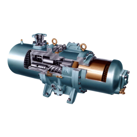
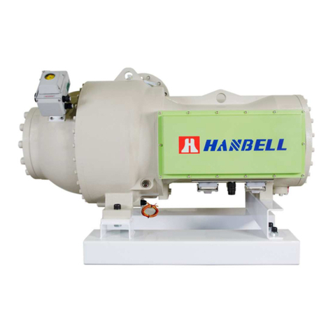
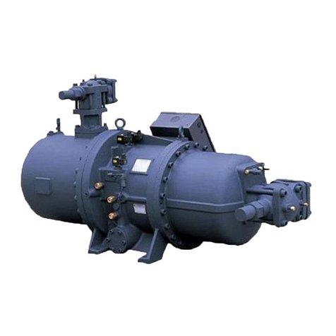
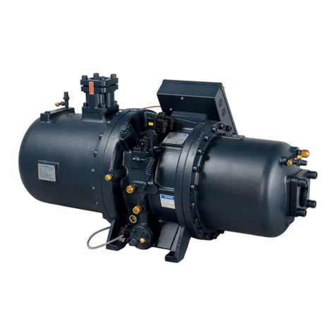
Hanbell RC2 Series User manual


Contents
1. General ........................................................................................................................................ 1
2. Specifications and concept of design ...................................................................................... 1
2.1 Compressor nomenclature............................................................................................... 1
2.2 High Voltage compressor specifications ........................................................................ 2
2.3 Compressor construction................................................................................................. 2
2.4 Design features ................................................................................................................. 3
2.5 Compression process....................................................................................................... 4
2.6 Capacity control system ................................................................................................... 4
2.6.1 4-step capacity control system .............................................................................. 4
2.6.2 Continuous (step-less) capacity control system.................................................. 5
2.6.3 Dual capacity control system (optional)................................................................ 6
2.7 Compressor volume ratio (Vi) .......................................................................................... 6
2.8 Application limits............................................................................................................... 6
2.9 MCC & LRA ........................................................................................................................ 8
3. Lubricants ................................................................................................................................... 9
3.1 Lubricant table................................................................................................................... 9
3.2 Pre-cautions of changing oil ............................................................................................ 9
3.3 Oil change ........................................................................................................................ 10
4. Compressor lifting and installation ........................................................................................ 11
4.1 Compressor lifting........................................................................................................... 11
4.2 Compressor mountings .................................................................................................. 12
4.3 Piping work ...................................................................................................................... 12
4.4 Installing the compressor in a sloping position ........................................................... 13
4.5 Compressor outline drawings....................................................................................... 14
4.6 Compressors accessories.............................................................................................. 17
4.7 Installation and connection of the compressor............................................................ 27
5. Electrical data and design ....................................................................................................... 29
5.1 Direct-on-line start for High Voltage compressor......................................................... 29
5.1.1 Power supply wiring application.......................................................................... 29
5.2 Compressor protection devices..................................................................................... 30
5.2.1 Protection devices for High Voltage compressor .............................................. 31
5.3 Power supply ................................................................................................................... 31
5.4 Selection of magnetic contactors .................................................................................. 32
5.5 Grounding ........................................................................................................................ 33
6. Operation and maintenance ....................................................................................................33
6.1 Compressor starting ....................................................................................................... 33
6.2 Troubleshooting .............................................................................................................. 35
6.3 Compressor check list .................................................................................................... 36
7. Applications .............................................................................................................................. 37
7.1 Additional cooling ........................................................................................................... 37
7.2 Economizer applications ................................................................................................ 38
7.3 Parallel system applications .......................................................................................... 38
7.4 Oil pump application ....................................................................................................... 39
7.5 Important notes of compressor applications................................................................ 40
8. Warranty.................................................................................................................................... 40


1
1. General
HANBELL RC2 series semi-hermetic screw compressor is developed especially for applications in air-conditioning
and refrigeration. With high operating load design, each HANBELL compressor is of high efficiency and reliability in all
operating conditions such as thermal storage, heat pump system & refrigeration. Each HANBELL compressor has the
latest and advanced 5-to-6 Patented Screw Rotor Profile designed to ensure high capacity and efficiency in all
operating conditions. Each unit is carefully manufactured and inspected by high precision THREAD SCREW ROTOR
GRINDING MACHINE, CNC MACHINING CENTER, and 3D COORDINATE MEASURING MACHINE. Each HANBELL
compressor follows ISO 9001 quality system. This certification assures that its quality is controlled under severe quality
procedures and good service to all customers.
High Voltage RC2 series compressor is equipped with separated radial and axial bearings, liquid injection and
economizer connection, PTC motor temperature thermistors and discharge temperature thermistors, a motor protector,
and other accessories. The complete accessories and their new designs guarantee the compressor has the best
reliability, longest bearing life during heavy duty running and strict operating conditions.
This Technical Manual contains information about lifting, dimensions, installation, operation, applications and basic
trouble-shooting. It is strongly recommended that contents of this manual should be referred carefully prior to lifting,
installation, and commissioning of High Voltage RC2 compressor in order to prevent any accident or damage. Please
contact HANBELL or its local distributors/agents for more information or further assistance.
2. Specifications and concept of design
2.1 Compressor nomenclature
RC 2 – x x x x x
Refrigerant Code A = R134a
B = R22, R407C, R404A, R507A
Compressor’s Displacement at 50Hz (m3/hr)
RC model 2nd Version

2
2.2 High Voltage compressor specifications
a. RC2-A
COMPRESSOR MOTOR
Displacement
60 / 50Hz Cap. Control (%) Nominal
Hp Voltage (V)
Hydrostatic
Pressure
Test
WEIGHT
MODEL
m3/hr
Rated
Speed
60 / 50Hz
VI
STEP STEPLESS
Type
60Hz 50Hz
Starting
60Hz 50Hz
Insulation Protection
kg/cm2g kg
RC2-1090A 1310/1089 35, 50, 75, 100 35~100 247 205 1710
RC2-1280A 1535/1276 30, 50, 75, 100 30~100 286 238 1890
RC2-1520A 1832/1523
3550/2950
2.2
2.6
3.0
3.5
25, 50, 75, 100 25~100
3 Phase, 2 Pole,
Squirrel Cage,
Induction Motor
331 275
DOL
3300
4160
6600
6000
10000
Class F
PTC Protection
42
1940
b. RC2-B
COMPRESSOR MOTOR
Displacement
60 / 50Hz Cap. Control (%) Nominal
Hp Voltage (V)
Hydrostatic
Pressure
Test
WEIGHT
MODEL
m3/hr
Rated
Speed
60 / 50Hz
VI
STEP STEPLESS
Type
60Hz 50Hz
Starting
60Hz 50Hz
Insulation Protection
kg/cm2g kg
RC2-1090B 1310/1089 35, 50, 75, 100 35~100 402 335 1710
RC2-1280B 1535/1276 30, 50, 75, 100 30~100 471 392 1890
RC2-1520B 1832/1523
3550/2950
2.2
2.6
3.0
3.5
25, 50, 75, 100 25~100
3 Phase, 2 Pole,
Squirrel Cage,
Induction Motor
534 443
DOL
3300
4160
6600
6000
10000
Class F
PTC Protection
42
1940
Compressor weight kg
Model 380V 6000V 10000V
RC2-1090 1430 1710 ---
RC2-1280 1580 1890 ---
RC2-1520 1630 1940 ---
Nominal Horse Power:
All the above Nominal Hp’s are not equal to the maximum compressor Hp. Please refer to Hanbell selection software’s
output for rated current and Maximum Continuous Current-M.C.C according to various operating conditions while
selecting sizes of contactor, cable, fuse and wire, etc…
2.3 Compressor construction
High Voltage RC2- 1090, RC2-1280, RC2-1520 construction
30 9
125
18
10
11 17
19
16 15 20 21 25 22
678
23
27
13 14 426
129
2
28
24
3
Figure 1: Compressor construction
Item Description Item Description Item Description Item Description
1 Compressor casing 9 Motor rotor spacer ring 17 Discharge fixed ring 25 Suction bearing
inner/outer spacer ring
2 Motor casing 10 Piston 18 Disc spring 26 Discharge bearing
inner/outer spacer ring
3 Motor cover casing 11 Piston spring 19 Bearing lock nut 27 Seal plate
4 Bearing seat 12 Piston rod 20 Male rotor 28 Motor cooling inlet
5 Piston cylinder 13
Bearing seat cover
plate 21 Suction bearings 29 Oil inlet connection
6 Motor rotor assembly 14 Solenoid valve 22 Suction bearing fixed
ring 30 Piston cylinder cover
7 Motor stator assembly 15 Slide valve 23 Sight glass
8 Motor rotor washer 16 Discharge bearings 24 Power bolt

3
2.4 Design features
HANBELL screw compressors feature simple and robust construction by elimination of some components such as
pistons, piston rings, valve plates, oil pumps which are found in reciprocating compressors. Without these components,
screw compressors run with low noise level, minimized vibration, high reliability and durability. HANBELL screw
compressors are of two-shaft rotary displacement design with the latest and advanced 5:6 patented screw rotors.
Screw rotors are precisely installed with roller bearings, i.e. radial bearings at both suction and discharge ends as well
as angular contact ball bearings i.e. axial bearings at discharge end. A three-phase, two-pole squirrel-cage induction
motor drives the compressor. The motor rotor is located on the shaft of male screw rotor. Motor cooling is achieved by
independent motor cooling system.
Compressor technical features:
Full product range- Hanbell provides a variety of high voltage motors, 3300V, 4160V, 6600V, 6000V and 10000V, for
customer’s selection, which are compatible with R22, R134a, R404A, R507A and R407C. Other special working
voltage and frequency are available after consulting Hanbell.
Multinational patents of high-efficiency screw rotors- The new 5:6 high efficiency screw rotor profile is patented in
Taiwan, UK, US, and China. This new large-volume, high-efficiency rotor profile is designed especially for modern
refrigerant characteristics. High-efficiency screw rotors are accomplished by using precision CNC machining centers,
rotor milling machines, rotor grinding machines. Strict ISO 9001 process controlling and the application of precise
inspection equipments, such as ZEISS 3D coordinate measuring machines, ensure high-efficiency, high-quality, low-
noise and low-vibration HANBELL RC2 series screw compressors.
Precise capacity control- Slide valve for capacity control is located in the compressor cylinder. Slide valve is actuated
by oil with solenoid valves.
Wide range of operating conditions- Evaporating temperatures can be between -25℃ and 15℃while condensing
temperatures can be 65 maximum.℃
High-efficiency motors- Premium-grade low-loss core steel with special independent motor cooling design provides
the highest operating efficiency no matter how strict operating conditions are.
Long-life bearings and high reliability- The screw compressors utilize a combination of 10 axial and radial bearings
to ensure longer bearing life and higher compressor reliability.
Double-walled rotor housing- Double casing structure with high strength inner ribs has been designed to minimize
noise and ensure rigidity. The rotor housing is made of high-strength gray cast iron FC25 that is extremely stable,
therefore no expansion will occur even at high-pressure condition. These casings are machined by computer aided
machining centers and inspected by precision measuring machines to enhance reliability.
Perceptive electronics- High Voltage series screw compressors are equipped with PTC thermistors and motor
protection module which could monitor discharge and motor coil temperatures. The oil flow switch and oil temperature
thermistors are optional for your application.
Independent motor cooling and liquid injection- Independent motor cooling and liquid injection to chamber greatly
help heat dissipation in heavy-duty condition.
High Voltage series compressors not only inherit RC2 series compressors’ characteristics of high efficiency & reliability
design mentioned above, but are also designed with the following new advantages to meet customers’ needs:
1. Design the fittest high-efficiency motor for respective refrigerants, operating conditions and applicable power.
2. Dual capacity control provides flexibility in change of control (optional).
3. Floating ECO port design results in partial load effective economizer operation.
4
2.5 Compression process
As shown in Figure 2 below, during the rotation of the rotors, the meshing shifts from the suction side to the discharge
side. The meshing rotors enclose a working space, which is continuously reduced as it moves in the axial direction.
This causes a V-shaped lobe space between each male and female lobes. This lobe space is maximum at suction and
sealing process. As the rotors rotate further, the new meshing at the suction side closes the V-shaped lobe space. The
lobe space is then constantly reduced by continuous intermeshing of the lobes (compression process).
A reduction in lobe space takes places during its movement from the suction side of the rotors towards the discharge
side. The volume is steadily reduced and it is thereby compressed in the sealed condition. As soon as the peaks of the
rotor teeth are free to the outlet port, compressed vapor is discharged to the high-pressure side and flows to the oil
separator where the high-pressured gas is separated from lubrication oil. The size and geometry of the outlet port
determine the so-called “internal volume ratio (Vi)” of the compressor. This ratio must have a defined relationship with
operating pressure ratio to avoid losses in efficiency due to under or over compression.
Figure 2: Compression process
2.6 Capacity control system
High Voltage series screw compressors are equipped with either 4-step capacity control system or continuous (step-
less) capacity control system. Both of these capacity control systems consist of a modulation slide valve, a piston rod, a
cylinder, a piston and piston rings. The slide valve and the piston are connected by a piston rod. The principle of
operation is using oil pressure to drive the piston in the cylinder. For example, lubrication oil flows into the cylinder due
to oil pressure of which resultant is bigger than spring force plus the force of high-pressured gas in the other side of the
piston. Oil inside the cylinder pushes the piston toward the suction side. When the slide valve moves toward the
suction side, the effective compression volume is increased in the compression chamber. This means the displacement
of refrigerant gas is also increased; as a result, the refrigeration capacity is also increased. However, when any of
solenoid valves (for 4-step capacity control system) is opened, the high-pressured oil in the cylinder will be bypassed to
the suction side. In this way, the piston together with the slide valve will move toward partial load positions (either 25%,
or 50%, 0r 75% for 4-step capacity control system) and then some of the refrigerant gas will be bypassed from the
compression chamber back to the suction side. As a result, the refrigeration capacity is decreased because of
reduction in displacement of refrigerant gas flowing in the system.
A piston spring is used to push the piston back to its initial position, i.e. the minimum-load position, in order to reduce
starting current for the next start. If the compressor starts at full load, over current may happen. Orifices are used to
maintain a suitable amount of oil flow into the cylinder. Solenoid valves (SV1 and SV2) for step-less control are
controlled by a micro controller or a temperature switch to modulate the position of the piston smoothly for loading, or
unloading or stable.
If solenoid valves and the piston do not work well in the capacity control system, this may result in capacity control
failure. Before compressors stop, HANBELL strongly recommends that the unloading solenoid valve for step-less
control system or the minimum-load solenoid valve for step control system should be kept opened for 30~60 seconds
so the piston in the cylinder can approach the minimum-load position for lighter duty in next start.
2.6.1 4-step capacity control system
There are three solenoid valves equipped that control compressor capacity from the minimum load (please refer to 2.2
for different minimum capacity in each model) to full load (100%). In general, normally closed (NC) solenoid valves are
used to control variation of loads. For the compressor with 4-step capacity control system, usual use the sequence of
min%-50%-75%-100% to load the capacity of compressor and use the sequence of 100%-75%-50%-min% to unload
the capacity.
(A) Suction and sealing
(B) Compression
(C) Discharge

5
Figure 3: 4-step capacity control
Note: For 4-step capacity control system, Hanbell equips
normally closed (NC) solenoid valves as standard
accessory. To equip normally open (NO) solenoid
valves, please specify it to Hanbell when placing
orders.
2.6.2 Continuous (step-less) capacity control system
In continuous (step-less) capacity control system, a normally closed solenoid valve SV1 (for loading) and a normally
closed solenoid valve SV2 (for unloading) are equipped respectively as shown in Figure 4. These two solenoid valves
are controlled by chiller temperature controller or micro controller, the refrigeration capacity hence can be modulated at
anywhere within min% ~ 100%
It is very important for any controller to control loading and unloading in moderate condition. For smooth modulation,
HANBELL installs an orifice in loading oil line to prevent too fast loading.
Figure 4: Step-less capacity control
Note: 1. For continuous(step-less) capacity control system, Hanbell installs
one normally closed solenoid valve for loading and another normally
closed solenoid valve for unloading as standard. If it is necessary to
install other type of solenoid valves, please specify it to Hanbell
when placing orders.
2. To equip loading orifice or not depends on system applications,
please discuss it with Hanbell when placing orders.
4-step capacity
control system SV2(NC) SV3(NC) SV4(NC)
100%full load
Not
energized
Not
energized
Not
energized
75%of partial load
Not
energized
Not
energized energized
50%of partial load
Not
energized energized Not
energized
min%(for starting)Energized Not
energized
Not
energized
SV1(NC) SV2(NC)
Start Not energized energized
Loading energized Not energized
Unloading Not energized energized
Stable Not energized Not energized
25% or 30% or 35 %
partial load
50 % partial load 75 % partial load 100 % full load

6
V
Pd
Pd'
V
Pd<Pd'
P
Pd, Pd'
V
Pd=Pd'
P
Pd>Pd'
Pd'
Pd
P
2.6.3 Dual capacity control system (optional)
Hanbell can provide dual capacity control system which is compatible for 4-step & step-less capacity control for
customers’ ease of change as shown in Figure 5, and its control logic is the same as explained in either 2.6.1 or 2.6.2.
2.7 Compressor volume ratio (Vi)
The volume ratio (Vi) of the compressor can be defined as the ratio of suction volume to discharge volume in the
compressor. The smaller the concavity of slide valve in the discharge end, the larger the volume ratio. The volume ratio
directly affects the internal compression ratio (Pi). Low Vi corresponds to low Pi and high Vi corresponds to high Pi. In
the equation below, in order to prevent over or under compression, the system compression ratio (CR) should be equal
to compressor’s internal compression ratio (Pi). Please refer to P-V (pressure – volume) diagram below to figure out
this relation.
CR =Pd/Ps
Pi = Vi k
Vi = Vs/Vd
CR: system compression ratio Pi: internal compression ratio
Vi: internal volume ratio Pd: system condensing pressure (absolute pressure)
Pd’: discharge pressure (absolute pressure) Ps: suction pressure (absolute pressure)
Vs: suction volume Vd: discharge volume
K: refrigerant specific heat ratio
2.8 Application limits
Compressor application limits vary significantly with types of refrigerant used. Application limits shown below are based
on operating conditions, i.e. saturated suction and discharge temperatures. For continuous long-term operation , it is
important to operate within these limits to maintain compressors’ life expectancy. Operating at extra low saturated
suction temperatures may cause oil management and motor cooling problems, while operating at extra high saturated
condensing temperatures may shorten compressors’ lifetime due to insufficient motor and compressor chamber cooling.
.
Under com
p
ression
(
CR > Pi
)
Over com
p
ression
(
CR < Pi
)
CR = Pi
Loss of work Loss of work
1 2
3
4
Ps
1 2
3
4
Ps
Ps
1
2
3
4
Figure 6: P-V Diagram
Fig. 5 Steps & Step-less control
Figure 5: Solenoid valves for dual
capacity control

7
R134a Application Limits R22 Application Limits
R407C Application Limits R404A&R507 Application Limits
Note:
1. Different types of motor, A1, A2, B1 and B2 applies to respective refrigerants and operating conditions as shown in
the above application limits.
2. When High Voltage series screw compressors operate under partial or full load within application limits, motor and
discharge temperatures will rise concurrently. In order to keep compressors’ continuous running safe, Hanbell
recommends using the following additional cooling devices :
(1) Oil cooler (2) Liquid injection to chamber
Please refer to Hanbell selection software for the application of additional cooling systems.
Hanbell recommends monitoring oil pressure differential and keeping it 4kg/cm2g over the suction pressure for
adequate seal, lubrication and capacity control by pressure differential switches passively or by additional oil pumps
actively. Especially under operating conditions with low condensing temperatures and high evaporating temperatures
like applications in water-cooled flooded chillers, high-low pressure differential tends to be less than 4kg/cm2g, The
installation of oil pumps is recommended to ensure regular oil supply.
Please contact Hanbell to verify potential operating conditions outside the application limits shown above.
3. The minimum discharge superheat is recommended to be kept 10K higher than the condensing temperature
(normally discharge superheat is around 20K for R134a and 30K for R22, R407C) to avoid liquid compression and
lubrication failure.

8
2.9 MCC & LRA
Refrigerant : R134a
50Hz 60Hz Unit: Ampere
6000V 10000V 3300V 4160V 6600V
Model
MCC LRA MCC LRA MCC LRA MCC LRA MCC LRA
RC2-1090A 20 128 12 80 44 263 35 196 22 144
RC2-1280A 23 133 14 76 50 267 40 205 25 147
RC2-1520A 27 137 16 90 58 276 46 230 29 152
Refrigerant : R22, R407C, R404A
50Hz 60Hz Unit: Ampere
6000V 10000V 3300V 4160V 6600V
Model
MCC LRA MCC LRA MCC LRA MCC LRA MCC LRA
RC2-1090B 32 163 19 93 70 330 56 273 35 185
RC2-1280B 38 177 23 101 82 377 65 301 41 192
RC2-1520B 42 201 25 112 92 424 73 343 46 222

9
3. Lubricants
The main functions of lubrication oil in screw compressors are lubrication, internal sealing, cooling and capacity control.
Positive oil pressure in the cylinder pushes the piston together with the slide valve that is connected by a piston rod to
move forward and backward in the compression chamber. The design of positive pressure differential lubrication
system makes RC2 series normally omit an extra oil pump which is necessary for reciprocating compressors. However,
in some special applications, it is still necessary to install an extra oil pump to screw compressors for safety.
Bearings used in RC2 series compressors require a small and steady quantity of oil for lubrication. Oil injection into the
compression chamber creates a film of oil for sealing in the compression housing to increase efficiency and also can
dissipate part of compression heat. In order to separate oil from refrigerant gas, an external oil separator is required to
ensure the least amount of oil carried into the system.
Please pay more attention to the oil temperature, which is crucial to compressor bearings’ life. Oil has a much lower
viscosity at high temperatures. Too low viscosity of oil will result in poor lubrication and heat dissipation in the
compressor. Viscosity is recommended to keep over 10mm2/s at any temperatures for oil. Oil temperature in the oil
sump should be kept above the saturated condensing temperature to prevent refrigerant migration into lubrication
system. Oil has a higher viscosity in low ambient temperature circumstances. When viscosity is too high, slow flow
speed of oil into the cylinder may result in too slow loading of the compressor. To solve this problem, use of oil heaters
can warm up oil before start.
If the compressor operates under critical operating conditions, an extra oil cooler is required – please refer to Hanbell
selection software for the required capacity and oil flow of the extra oil cooler. High-viscosity oil is recommended to
apply in high operating conditions because high discharge temperatures will make viscosity of oil lower. Oil return from
the evaporator may be insufficient in such as refrigeration systems, flooded chillers…etc. , in which it’s difficult for oil to
be carried back.
3.1 Lubricant table
Applicable oil types (R22)
SPECIFICATION UNITS HBR -B10 HBR -A02 HBR -A04 HBR -B09 HBR -B02 HBR -B01
COLOR, ASTM 1.5 L1.0 L1.0 −−−
SPECIFIC GRAVITY 0.883 0.914 0.925 0.95 1.01 1.05
40℃56.0 54.5 96.5 175 168 298
VISCOSITY 100℃mm2/s (cSt) 7.0 6.07 8.12 16.5 20.2 32.0
FLASH POINT ℃220 188 198 265 290 271
POUR POINT ℃-40 -35 -25 -30 -43 -35
T.A.N mg KOH/g 0.01 0.00 0.01 −−−
COPPER STRIP 100 /3hr℃1a 1a 1a −−−
MOISTURE ppm 15 20 20 −−−
FLOC POINT ℃-75 -45 -35 −−−
DIELETRIC STRENGTH (2.5mm) kV 75 50 50 46.6 −−
Applicable oil types (R134a, R404A, R407C)
SPECIFICATION UNITS HBR -B05 HBR -B08 HBR -B09 HBR -B04
COLOR, ASTM −−−−
SPECIFIC GRAVITY 0.945 0.94 0.95 0.95
40℃64 131 175 215.9
VISCOSITY 100℃mm2/s (cSt) 8.9 14.53 16.5 20.8
FLASH POINT ℃266 254 265 271
POUR POINT ℃-43 -36.5 -30 -25
T.A.N mg KOH/g
−−−−
COPPER STRIP
100 /3hr℃−−−−
MOISTURE ppm
−−−−
FLOC POINT ℃−−−−
DIELETRIC STRENGTH 2.5mm kV −−46.6 −
Note: For other applicable oil types, please consult HANBELL for further approval.
3.2 Pre-cautions of changing oil
1. Use only qualified oil and do not mix different brands of oil together. Choice of oil should match characteristics of the
refrigerant used. Some types of synthetic oil is incompatible with mineral oil. Oil remained in the compressor should be
totally cleaned up in the system before charging different brands of oil. Charge the compressor with oil for the first start
and then change it into new oil again to ensure that there’s no mix at all.

10
2.When using polyester oil for chiller systems, please make sure not to expose oil to the atmosphere for prevention
of change in its property. Therefore, it is necessary to vacuum the system completely when installing the compressor.
3. In order to ensure no moisture inside the system, it is suggested to clean the system by charging it with dry Nitrogen
and then vacuum it repeatedly as long as possible.
4. It is a must to change oil especially if the motor has burned out because acid debris may still remain inside the
system. Please follow the procedures mentioned above to change oil in the system. Check acidity of oil after 72 hours
of operation and then change it again until acidity of oil becomes normal.
5. Please contact Hanbell local distributors/agents for choices of oil to be used.
3.3 Oil change
Lubrication oil is an important element in chiller systems. The main functions of lubrication oil in the screw compressor
are lubrication, internal sealing, cooling and capacity control. Some problems which may exist in the system are as
below.
1. Foreign debris contaminates lubricant and causes clog in oil filter.
2. Moisture in the system will make the system acid and motor corroded.
3. When the system is under an operating condition with high discharge temperature for a long time, oil viscosity will
decrease and shorten bearing’s life.
The correct ways to change lubrication oil are as below
1. Change oil periodically: Check lubrication oil every 10,000 hours of continuous running. For the first operation of the
compressor, it is recommended to change the oil and clean the external oil filter after running 2,000 hours. Check the
system whether clean or not and then change oil every 20,000 hours or after 3 years’ continuous running while the
system operates in good condition.
2. Debris in the system may block up external oil filter. To avoid this problem, it is recommended to add an oil pressure
differential switch. When oil pressure differential before and after the external oil filter is over the set-point, the system
should stop to protect compressor from oil loss.
3. If the system is under an operating condition with high discharge temperature for a long time, it is recommended to
check oil quality every 2 months. If the elements of oil have changed, change oil immediately.
4. Acid oil will shorten motor’s life. Check acidity of oil periodically. If it is below pH6, change oil immediately as well as
the dryer filter to ensure no moisture in the system.
5. After change of the burned motor, it is necessary to check oil condition every month. Moisture and acidity of oil
should be checked.

11
4. Compressor lifting and installation
4.1 Compressor lifting
Each HANBELL screw compressor has been carefully tested at the factory and every precautionary measures have
been taken to make sure that compressors will keep in perfect condition when reach customers’ work. After the
compressor arrives at your warehouse, please check if its crate is kept in good condition and check all the compressor
accessories with shipping documents to see if there is any discrepancy.
When lifting the compressor, it is recommended to use a steel chain or steel cable which can be used for loading
capacity of 3000kgf as shown in the figure below.
Make sure that chains, cables or other lifting equipments are properly positioned to protect the compressor and its
accessories from damaging. Keep the compressor in horizontal position when lifting, and prevent it from crashing or
falling on the ground, hitting the wall or any other accident that may damage it or its accessories.
Fi
g
ure: 7 Liftin
g
the com
p
ressor with steel chain or steel cable

12
4.2 Compressor mountings
The position of the compressor in refrigeration system should be accessible and make sure the chiller base or its site is
far away from any heat source to prevent heat radiation. The compressor should also be installed as close as possible
to the power supply for easier connection and it’s a must to keep good ventilation and low humidity condition in the site.
Please make sure that the frame or support is strong enough to prevent vibration and noise when compressor is
running and its clearance is enough for compressors’ future overhauling work.
The compressor must be installed horizontally. To prevent vibration transferred from the structure and piping of the
chiller during operation, cushions or anti-vibration pads (mounting pads) should be installed. The installation of anti-
vibration pads is shown in Figure 8. Bolts can not be tightened until some slight deformation of rubber pads is visible.
4.3 Piping work
Improper piping works could cause abnormal vibration and noise that might damage compressor. Please pay attention
to the following points to prevent any accidents:
1. Clean the system after welding of piping to avoid any swarf or debris contained inside the system because it may
cause serious damage to compressor during operation.
2. In order to reduce vibration in piping, it is recommended to install muffler on discharge piping and economizer piping.
In discharge piping, use of flexible stainless steel piping is also helpful to reduce vibration. Muffler should be installed
as close to economizer port or discharge port as possible.
3. The material of suction and discharge flange bushings is forged steel and it can be welded directly with piping
connection. Welding of flange bushing onto piping must be cooled down by ambient air. Do not use water to cool it
down because water quenching will destroy its structure.
4. Flowing gas will cause resonance especially in discharge or economizer piping, so it is necessary to avoid the
frequency that results in resonance between compressor and piping. It is also necessary to consider operating
condition, flowing speed of refrigerant, and compressor’s vibration frequency. The inherent harmonic frequency
approximates 250Hz for 50Hz application and 300Hz for 60 Hz application. Their multiples should be considered as
well.
5. It is recommended that the position of the compressor be higher than that of the evaporator.
Figure 8: Installation of anti-vibration pads

13
4.4 Installing the compressor in a sloping position
Figure 9 shows a 15° limit of oblique angle for installation of compressor. In case the oblique angle is higher than the
limit, compressor will be shut down easily. For special applications like the installation in ships, fishing boats, etc…,
where the oblique angle might exceed the limit, external oil separators, oil tanks and related accessories are
recommended to be installed. Please contact HANBELL or local distributors for further layout recommendation.
Figure 9: Limits of oblique angle for the installation of the
compressor

14
4.5 Compressor outline drawings
RC2-1090

15
RC2-1280

16
RC2-1520

17
4.6 Compressors accessories
To supply “Total Solution” for customers, Hanbell designs complete standard and optional accessories according to
various application requirements for safe and steady running as well as the best performance of compressors.
1. Compressor standard and optional accessories
●:Standard, △:Optional, Χ:No need
RC2-
Model &Accessory
1090 1280 1520
Steps or Step-less capacity control system ●●●
Dual capacity control system △△△
Horizontal check valve ●●●
Suction & discharge connection bushings ●●●
Suction & discharge stop valves △△△
PTC thermistor ●●●
IP54 cable box ●●●
INT69HBY motor protector ●●●
Liquid injection system (solenoid valve + expansion
valve) △△△
Economizer △△△
Pt100 or Pt1000 temperature sensors- (motor coil
temp. monitoring) ●●●
Safety valve △△△
Explosion-proof accessories △△△
Micro controller △△△
Mounting pad △△△
Sound jacket △△△
Oil filter pressure differential switch △△△
External oil separator △△△
Lubrication oil △△△
150W/300W oil heater ΧΧΧ
Oil level switch ΧΧΧ
Oil drain valve △△△
External oil filter △△△
Oil flow switch △△△
Oil cooler △△△
Oil pump △△△
Note: The accessory chart is just for reference only. Actual specification and accessories enclosed might vary with
different quotation and agreement respectively. If any optional accessory is required and out of above mentioned
standard accessory, please contact Hanbell for detailed specifications.
Other manuals for RC2 Series
2
This manual suits for next models
9
Table of contents
Other Hanbell Compressor manuals
Popular Compressor manuals by other brands

Kooper
Kooper 2196438 User instructions

BENDIX
BENDIX BA-921 COMPRESSOR-STD-CLOSED ROOM Service data sheet

Lindell Audio
Lindell Audio 7X-500 user manual

Panasonic
Panasonic Matsushita DA51C72RCU6 Specification sheet

Airmec
Airmec HOBBY Series Maintenance and operation handbook

Scheppach
Scheppach HC60 instruction manual

Sherwin-Williams
Sherwin-Williams GTS-ProCart 283-584 owner's manual

MGF
MGF SIL-EOL Series Operating & maintenance instruction manual

EKOM
EKOM DK50 2V S Instructions for use and service manual

Trotec
Trotec PCPS 11-20V Original instructions

Draper
Draper DA6/181 manual

alca
alca AeroPressor instruction manual