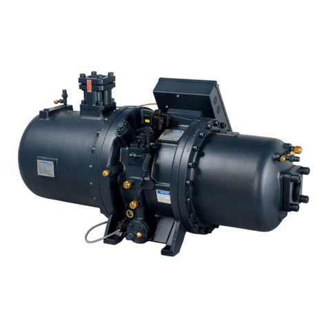
Hanbell RTM-090 User manual

[文件標題] [日期]
1
Vol. 1.2 © 2020 Hanbell Precise Machinery Co., Ltd.
All rights reserved
Magnetic Centrifugal Compressor
RTM-090

[文件標題] [日期]
2
Vol. 1.2 © 2020 Hanbell Precise Machinery Co., Ltd.
All rights reserved
Contents
.....................................................................................................................................................................
Contents...................................................................................................................................................................2
Chapter 1. Introduction............................................................................................................................................4
Features ...............................................................................................................................................................4
Ambience.............................................................................................................................................................4
Chapter 2. Basic design...........................................................................................................................................5
2.1 Compressor nomenclature.............................................................................................................................5
2.2 Application limits..........................................................................................................................................5
2.3 Compressor specifications.............................................................................................................................6
2.4 Compressor outline........................................................................................................................................7
2.5 Connections...................................................................................................................................................8
2.5.1 Suction/discharge/economizer flange size..............................................................................................8
2.5.2 Butterfly valve ......................................................................................................................................10
2.5.3 Check valve ..........................................................................................................................................11
3. Suction Structure...............................................................................................................................................12
3.1 Inlet Guide Vanes........................................................................................................................................12
3.1.1 Control of inlet guide vanes..................................................................................................................12
3.2 Vane actuator control ..................................................................................................................................13
3.2.1 Actuator data.........................................................................................................................................13
3.2.2 Electrical connections...........................................................................................................................14
3.2.3 Wiring...................................................................................................................................................14
3.2.4 Control info...........................................................................................................................................15
3.2.5 Troubleshooting....................................................................................................................................17
3.3 Capacity adjustment ....................................................................................................................................18
3.4
Equation of safety margin line...................................................................................................................18
3.5 Hot gas bypass (HGBP)...............................................................................................................................19
3.6 Middle pressure stop valve..........................................................................................................................20
4.1 Motor cooling..............................................................................................................................................21
4.1.1 Heater....................................................................................................................................................21
4.1.2 Pt100 Thermostat..................................................................................................................................21
4.2 Liquid returned from motor and bearings....................................................................................................22
4.3 Motor Temperature Control.........................................................................................................................23
4.4 Motor connection.........................................................................................................................................23
4.4.1 Voltage & Frequency............................................................................................................................23
4.4.2 Components of inverter ........................................................................................................................23

[文件標題] [日期]
3
Vol. 1.2 © 2020 Hanbell Precise Machinery Co., Ltd.
All rights reserved
4.4.3 Grounding.............................................................................................................................................24
4.4.4 Cable of main power input....................................................................................................................25
4.4.5 Connection notice.................................................................................................................................26
4.5 MCC (Maximum Continuous Current) of motor.........................................................................................26
5. Control line connection .....................................................................................................................................27
5.1 Magnetic Bearing Controller (MBC) info...................................................................................................28
5.2 MBC installation notice...............................................................................................................................28
5.4 MBC connection port..................................................................................................................................30
5.5 MBC connection data..................................................................................................................................31
5.5.1 Additional info. about connection port.................................................................................................31
5.5.2 Communication of MBC and PLC .......................................................................................................31
5.6 Total Harmonic Distortion (THD) info.......................................................................................................31
5.7 THD installation & fix.................................................................................................................................32
5.8 THD connector............................................................................................................................................33
5.9 Variable Frequency Drive (VFD) Connector..............................................................................................34
5.10 Parameter of inverter.................................................................................................................................34
6. Compressor lifting and installation....................................................................................................................35
6.1 Compressor lifting.......................................................................................................................................35
6.2 Compressor installation...............................................................................................................................35
7. Instructions........................................................................................................................................................37
7.1 Accessories..................................................................................................................................................37
7.2 Valves..........................................................................................................................................................37
7.3 Testing before power supply .......................................................................................................................37
7.4 System requirement.....................................................................................................................................38
7.5 Control requirement.....................................................................................................................................38
7.6 Others ..........................................................................................................................................................38

[文件標題] [日期]
4
Vol. 1.2 © 2020 Hanbell Precise Machinery Co., Ltd.
All rights reserved
Chapter 1. Introduction
This manual is intended as a guide for application engineers, consultants, sales engineers, and
HVAC designers to use Hanbell RTM series centrifugal compressors. The copyright of this technical
manual belongs to Hanbell Precise Machinery Co., Ltd.. Neither this publication nor any part of it may
be reproduced or transmitted in any form or by any means without the prior permission of Hanbell
Precise Machinery Co., Ltd..
Features
Refrigerant – R134a
Compressor – semi-hermetic design
Shaft –made of high-strength alloy
Impellers – closed type made of high-strength aluminum
Bearings – magnetic bearings
Motor –permanent magnet synchronous motor, independent cooling by liquid refrigerant
Enclosure - IP54 protection
Ambience
RTM series compressors should be stored and operated within the following ambient temperature.
Storage
:
-25℃~55℃
Operation(Water-cooled)
:
ET
:
2℃~14℃;CT:15℃~55℃
Note:
1.
Please refer to “Application limits” in chapter 2 for allowable operating conditions and Hanbell
selection software for detailed performance data.
2. For special application limits, please contact Hanbell.
3. Chapter 7 contains instructions for the use of other AC electrical components.
4. In a humid environment, the compressor housing and piping should be insulated to prevent
condensation.

[文件標題] [日期]
5
Vol. 1.2 © 2020 Hanbell Precise Machinery Co., Ltd.
All rights reserved
Chapter 2. Basic design
2.1 Compressor nomenclature
0:Air-Condition,△T=SCT-SST=30℃
1:Heat-Pump,△T=SCT-SST=40℃
RTM- X X X
Model
Magnetic Bearing Centrifugal Compressor
2.2 Application limits
10
15
20
25
30
35
40
45
50
55
60
0 2 4 6 8 10 12 14 16 18 20 22
Saturated Condensation Temperature (℃
℃
℃
℃)
Saturated Evaporation Temperature (℃
℃℃
℃)
Pr=3.0
Pr=2.5
Pr=2.0
Pr=1.5
Figure 2.1 RTM-090 application limits
Note: Please refer to the latest compressor selection software for specific compressor capacity.
Note: This range represents the range of FLA at
380V, and the limits for maximum condensation
temperature (SCT) and evaporation temperature
(SST) depend on the full load current and the
axial thrust of the compressor.

[文件標題] [日期]
6
Vol. 1.2 © 2020 Hanbell Precise Machinery Co., Ltd.
All rights reserved
2.3 Compressor specifications
Model RTM-090
Refrigerant R134a
Nominal cooling capacity USRT 400~450
Compressor
Type
Two-stage compression
Axial guide vane
control IGV 20~100% continuous
Frequency Hz 225
Motor
Type
3 Phase, 2 Pole, Permanent magnet
Starting
VFD
Voltage V 380~460±5%
Insulation
Class H
Protection
PT100*6
Transmission
Type
Direct-driven
Lubrication
Oil free
Dimension (LxWxH) m 1.3 X 0.8 x 0.7
Weight kg 1050
Hydrostatic pressure test kg/cm²g 22
Refrigerant heater kW 1x 0.3
Table 2.1 Compressor specifications
RTM-090 Performance
USRT RPM COP IPLV
400 13,000 6.53 11.0
450 13,500 6.33 10.5
Table 2.2 Compressor performance
Note: The performance is based on AHRI condition assuming a discharge check valve is installed.

[文件標題] [日期]
7
Vol. 1.2 © 2020 Hanbell Precise Machinery Co., Ltd.
All rights reserved
2.4 Compressor outline

[文件標題] [日期]
8
Vol. 1.2 © 2020 Hanbell Precise Machinery Co., Ltd.
All rights reserved
2.5 Connections
2.5.1 Suction/discharge/economizer flange size
Figure 2.3 Flange
Position Size
A B D E F G Piping
thick.
(JIS)
(GB)
RTM-090
Suction 8" 218
221.5
305 350 30 12 25 11
Discharge
6" 167
170.5
260 305 28 12 25 10.5
Mid.-
press.
(Eco.)
2 1/2"
77.5
77.5
140 175 20 8 19 7
Remarks ※Material- standard JIS 20kg/cm²g steel
unit: mm
※Thickness must be equal to the standard or larger
Table 2.2 Flange dimensions
Note:
1. Please weld steel pipes onto flanges by butt-welding and make sure debris has been cleaned,
otherwise the compressor might be damaged during running. Flow velocity in the discharge
side of the compressor could be as high as 15~20 m/sec. High-speed discharge gas will
make noise in discharge connection. In order to decrease the noise level, it’s recommended
to round sharp edges of joints of piping as shown in Figure 2.4
2. The discharge and suction piping is recommended to be one size larger to reduce pressure
drop and noise level. If the noise level is high in discharge side, it is suggested to increase
the piping thickness or enclose with acoustic foam shown in Figure 2.5.

[文件標題] [日期]
9
Vol. 1.2 © 2020 Hanbell Precise Machinery Co., Ltd.
All rights reserved
Figure 2.4 Discharge and suction piping
Note: Residue from welding might damage the compressor seriously.
1防熱橡膠
2鉛板層(2~3mm)
3隔音棉
4表層膠帶
Figure 2.5 Enclosure of piping connection
1
Heatproof rubber
2
Laminated lead
(2~3mm)
3
Acoustic foam
4
Gummed tape

[文件標題] [日期]
10
Vol. 1.2 © 2020 Hanbell Precise Machinery Co., Ltd.
All rights reserved
2.5.2 Butterfly valve
For easy maintenance, the butterfly valve can be installed in condenser inlet and liquid line before
expansion valve. When installing butterfly valve, the pipe must also be enlarged one size to effectively
reduce the pressure drop.
Butterfly valve
size A B C D E F G H J K L
2 1/2〞
65mm 121 48 58 97 162 111 16 11 32 64 20
3〞80mm 133 48 73 104 168 111 16 11 32 64 20
4〞100mm 171 52 94 120 191 111 16 11 32 64 19
5〞125mm 191 57 122 129 191 130 19 13 32 114
24
6〞150mm 219 57 149 141 203 130 19 13 32 114
24
8〞200mm 273 61 198 176 241 130 22 16 32 114
24
10〞250mm 332 70 248 217 273 155 30 22 51 114
27
Remark
※Dimension C is minima size when the valve opened totally unit:mm
※Operation Temp.:-29℃~260℃;Operation Pressure:1480psi
※Material- ASTAM351 GR CF8M stainless steel. Pressure level: ASME 150
※The butterfly valve is of wafer plate valves. Use ANSI 150 standard flange
Table 2.3 Flange size
Figure 2.6 Outline of butterfly size

[文件標題] [日期]
11
Vol. 1.2 © 2020 Hanbell Precise Machinery Co., Ltd.
All rights reserved
2.5.3 Check valve
To avoid the reverse rotation caused by emergency shutdown and protect active magnetic bearing
(AMB), under high-speed compressing, installation of a check valve installed in the discharge side is
necessary.
Size A(mm) B(mm) C(mm) E(mm)
6〞150mm 222.2 120.7 95.3 70
8〞200mm 279.4 163.5 116.7 74.6
Remark
※Operating temp.:-260℃~810℃
Hydraulic pressure testing: 31.6kg/cm
2
(API-598)
※Material - ASTAM351 GR CF8M stainless steel. Pressure level : ASME 150
※The check valve is of wafer plate valve. Use ANSI 150 standard flange
Table 2.4 Check valve size
No. Name Material
1 Valve CF8M
2 Disc shield A351- CF8M
3 Spring SUS316
4 Alignment pin SUS316
5 Bearing PTFE
6 Bolt SUS316
7 O ring PTFE
8 Eye ring A105
Figure 2.7 Pendulum check valve outline

[文件標題] [日期]
12
Vol. 1.2 © 2020 Hanbell Precise Machinery Co., Ltd.
All rights reserved
3. Suction Structure
3.1 Inlet Guide Vanes
The cooling capacity of RTM Series centrifugal compressors is modulated with change in angles of
inlet guide vanes. As illustrated in Figure 3.1, Refrigerant gas from the evaporator outlet flows through
the suction nozzle to the compressor suction inlet. After the inlet nozzle, gas flow velocity increases
due to the narrow passage. By changing angles of IGV, velocity and volume are changed as well as
cooling capacity.
Figure 3.1 Compressor inlet
3.1.1 Control of inlet guide vanes
Angles of inlet guide vanes are automatically controlled through a vane actuator with a lever arm, and
IGV opening ranges from 20% (minimum load) to totally open.
Opening of the vane actuator in percentage (%) has a linear relation to the control signal voltage.
However, cooling capacity does not relate the angle changes of guide vanes. Therefore, vane actuator’s
opening in percentage (%) is not the same as the cooling capacity in percentage (%)
Note 1:When inlet guide vanes are completely closed, a small hole will be formed in the middle to
keep a basic amount of gas flow into the compressor. When inlet guide vanes are fully closed,
only Min. mass flow passes so the smallest cooling capacity will be established.
Note 2:The lower pressure ratio stands for the lower minimum unloading capacity.
Actuator
Inlet guide vane
Impeller Suction

[文件標題] [日期]
13
Vol. 1.2 © 2020 Hanbell Precise Machinery Co., Ltd.
All rights reserved
Remark:1. IGV should be fully opened before start up. When HGBP opened before stop,please keep
IGV fully opened.
2. IGV operating range is 20%~100%.
3. Actuator signal feedback window:
Figure 3.2 OPEN Figure 3.3 SHUT
3.2 Vane actuator control
3.2.1 Actuator data
RATED POWER 1Phase, AC 220V±10%(50/60Hz)
1Phase, AC 110V±10%(50/60Hz)
INPUT SIGNAL 4~20mA‧DC;1~5V‧DC
OUTPUT SIGNAL 4~20mA‧DC
OUTPUT TORQUE 49N‧m(5kgf‧m)
OPERATION SPEED 15sec(50Hz);12.5 sec(60Hz)
TRAVEL ANGLE 0~90°
RATED OPERATION TIME Continuous (100%)
RESOLUTION Over 1/250
DEAD ZONE Max. 0.5%
PROTECTION Motor thermal protector (120ºC)
AMBIENT TEMPERATURE Ambient temperature within: -25~55ºC
RATED CURRENT 0.4A(220V);0.7A(110V)
MOTOR 20W
INSULATION GRADE Class E
INSULATION RESISTANCE Between power terminal – case : 500V·DC / 100MΩ
WITHSTAND VOLTAGE Between power terminal – case : 1500V·AC / 1 minute
WIRE INLET
G1/2×2
ENCLOSURE PROTECTION
NEMA-4X (IP-66)
WEIGHT
4.5kg
Table 3.1 Actuator data
Note:When operating at ambient temperature under 0℃, optional space heater is required to keep the
actuator inside dry. Otherwise, moisture may condense under low temperature and high humidity or
parts may shrink at low temperature.

[文件標題] [日期]
14
Vol. 1.2 © 2020 Hanbell Precise Machinery Co., Ltd.
All rights reserved
3.2.2 Electrical connections
When using standard wire wiring, cable diameter should be Φ9 ~ Φ11; if other wire is used, please
select the appropriate cable diameter, otherwise the water may penetrate.
Figure 3.2 Wiring diagram (220/110V)
Remark:1. 5A fuse or breaker should be installed in main power supply. Voltage stabilizer is required
to avoid the damage caused by the imbalance of voltage. (within 10%)
2. Signal wires for control should be shielded to prevent them from interference.
3. The actuator wiring shall not be parallel to the power cables.
3.2.3 Wiring
Make effective water proof if vinyl tubes or conduits are used:
Figure 3.3 Wiring
Cable gland
Protection cable
Single phase power source
(220/110V, 50/60Hz)
Output signal
4~20mA DC
Input signal
4~20mA DC

[文件標題] [日期]
15
Vol. 1.2 © 2020 Hanbell Precise Machinery Co., Ltd.
All rights reserved
3.2.4 Control info.
Figure 3.4 Control pack
Figure 3.5 Switcher
Select switch for off mode
Select switch for action mode
External terminal block
SPAN volume
Zero volume
Sensitivity volume

[文件標題] [日期]
16
Vol. 1.2 © 2020 Hanbell Precise Machinery Co., Ltd.
All rights reserved
※Direction mode
Either direct or reverse action is selectable at this switch.
※Selection of a mode during signal interruption:
A mode among open/stop/close is selectable at this switch in case of signal interruption
Note:When the input signal is less than 2mA, the actuator is judged to be interrupted and transferred
to the specified state, so the control device and signal 4~20mA must be adjusted correctly.
Select switch for action mode
Select switch for off mode
1 = Direct action
Input signal 20mA → Close
Input signal 4mA → Open
3 = Reverse action
Input signal 4mA → Open
Input signal 20mA → Close
Select switch 1 = Close action
Select switch 2 = Stop action
Select switch 3 = Open action

[文件標題] [日期]
17
Vol. 1.2 © 2020 Hanbell Precise Machinery Co., Ltd.
All rights reserved
※
Sensitivity volume:
※
ZERO/SPAN Setting:
Remark:
1. Before the compressor is shipped out from the factory, the zero and span knobs have been adjusted
to the best position. Do not adjust if not necessary. If adjustment is required, please use a small
screwdriver to turn gently (excessive force will cause damage in the knob).
2. When adjusting IGV, turn to the fully-close position and then do fully-open position adjustment.
※Note:Because the forward turn of the actuator is opposite to the IGV connecting rod’s, the zero
knob is fully opened while the span knob is fully closed. To avoid risk, this adjustment should be done
by qualified personnel.
3.2.5 Troubleshooting
TROUBLE
PROBABLE CAUSE
SOLUTION
Motor does not start up
1.
Power failed or dropped
2.
Signal failed or dropped
3.
Wire broken or disconnected
4.
Thermal protector functioned
5.
Limit switches functioned at an intermediate
position
6.
Motor advancer defective
7.
Control pack defective
1.
Check and supply power
2.
Check and input signals
3.
Change the wire or re-connect the
terminal
4.
Lower the ambient temperature
5.
Decrease duty rate
6.
Eliminate overload at valve
7.
Re-adjust the limit cam
8.
Change advancer (condenser)
9.
Change control pack
Sensitivity volume
* Sensitivity volume
Clockwise for higher
Counter clockwise for lower
* Max. sensitivity:
Resolution = 1/400
* Min. sensitivity:
Resolution = 1/100
SPAN Setting
ZERO Setting
* ZERO volume
CW = To increase (to OPEN direction)
Adjustable range - 25 ~ +25 %
* SPAN volume
CW = To increase (to OPEN direction)
Adjustable range - 50 ~ +200 %

[文件標題] [日期]
18
Vol. 1.2 © 2020 Hanbell Precise Machinery Co., Ltd.
All rights reserved
Aperture unfixable
(Hunting)
1.
Noise on signal line
2.
Noise on potentiometer
3.
Potentiometer and opening gear loose
1.
Check input signal
2.
Change potentiometer
3.
Check the fixing screws
Aperture does not match
input signal
1.
A wrong signal input
2.
Improper adjustment of ZERO/SPAN
3.
Potentiometer slipped
1.
Check the input signals
2.
Re-adjust ZERO/SPAN
3.
Re-adjust the aperture on the
potentiometer
Aperture signal does not
output
The opening signal is broken or poorly
connected Check the wiring connection
3.3 Capacity adjustment
According to AHRI standard, the capacity control range is 100%~25%. To achieve the best
performance, please follow the equation of safety margin line (refer chapter 3.4). The compressor
loading/unloading will work with the control of IGV:
1. Speed control:In general, cooling capacity will change about 2% by adjusting 1 Hz, or 2% of
leaving chilled water temp. change (approx. 0.1℃). Please refer to the following table:
Target leaving chilled water temp.: 7℃
Range <6.3℃6.3℃~6.8℃
6.8℃~7.2℃
7.2℃~7.8℃
>7.8℃
Control mode Fast unloading
unloading Neutral Loading Fast loading
Inverter output -1Hz -0.5Hz 0 +0.5Hz +1Hz
2. IGV control:When the frequency reaches to surge line, the unloading will be controlled by IGV.
3. The control for target water temp. is based on input signal, and output signal is used for setting the
frequency and opening of IGV. It is suggested to install anti-interference devices on chiller unit.
3.4 Equation of safety margin line
Description of Surge:
When the centrifugal compressor is at part load, the angle of guide vane becomes smaller and
refrigerant volume entering compressor also reduces; when the volume flow decreases to a certain
extent, surge and stall may occur. As shown in Figure 3.6 Typical fixed-frequency compressor
performance map, when compressors operate above the Surge Line, stall or surge may occur. When
the compressor surges, discharge pressure drops suddenly lower than the pressure in condenser so
high-pressured gas flows reversely to the compressor; therefore, gas flows inside the compressor
turbulently and it causes higher vibration and noise. Meanwhile, heat cannot be dissipated and
refrigerant gas cannot be cooled down; high temperature inside the compressor may cause severe
damage to high-speed shaft. In addition, alternatively varied pressure due to reverse flow may
influence compressor’s moving parts so bearings may bear heavier load and be damaged. Therefore,
compressor’s operating map must be confined below the Surge Line. Please refer to Hanbell selection
software for more details of allowable compressor operating map to prevent surge.

[文件標題] [日期]
19
Vol. 1.2 © 2020 Hanbell Precise Machinery Co., Ltd.
All rights reserved
Equation of safety margin line is a polynomial of IGV actuator’s opening in percentage.
While operating, beware the pressure difference exceed the safety margin.
z= a+b/x+cy+d/x2+ey2+fy/x+g/x3+hy3+iy2/x+jy/x2
1. a、b、c、d、e、f、g、h、i、j are constant
2. z=Hz(minima operating frequency);x= opening of IGV (%)/10;y= pressure ratio
Note:
1. When doing the minimum operation frequency calculation, 2~3Hz buffer will be considered.
2. Safety margin on each model is not the same, please contact HANBELL representatives.
3.5 Hot Gas By Pass (HGBP)
Hot gas bypass is to bypass gas refrigerant or liquid refrigerant from condenser into evaporator
through a proportional valve.
Function: When the load reaches certain value the surge would happen. To continue the low load
operation, the hot gas by pass valve can be opened to increase suction pressure and lower
discharge pressure as well as compression ratio.
Because hot gas bypass is to transfer compressed gas from the condenser (high-pressure side) to the
evaporator (low-pressure side), enormous noise may occur. It is recommended to enlarge the inner
diameter of piping after the HGBP valve to keep flow speed under 10 m/sec.
13500 rpm
13000 rpm
11700 rpm
10400 rpm
9100 rpm
7800 rpm
IGV 100%
I
GV
7
0%
I
GV
5
0%
I
GV
2
0%
13500 rpm operation
range at different IGV %
Operation range
IGV100% operation range
at different rpm
Pressure Ratio (Pr)
Cooling Capacity (kW)
Figure 3.6 Operating range

[文件標題] [日期]
20
Vol. 1.2 © 2020 Hanbell Precise Machinery Co., Ltd.
All rights reserved
In piping, the proportional valve should be installed as close as possible to the evaporator, and also at
another side of suction entry (motor side) to lower the noises.
Besides, a muffler or shield should be installed at the evaporator to prevent splashed liquid refrigerant,
which may damage the compressor.
Note1: The system with hot gas bypass is inefficient. It should be avoided whenever possible. Many
system applications still require hot gas bypass in order to avoid surge or maintain constant
chilled water temperatures from zero load to full load.
Note2: Required flow for HGBP depends on the difference between required minimum cooling
capacity and the minimum load compressor can reach. If the IGV is at minimum opening and
cooling capacity is 50%, and end user needs 20%. The pipe diameter and flow need to be
considered based on the 30% difference.
3.6 Middle pressure stop valve
Between the ECO port of the compressor and the economizer, it is recommended to install a stop valve
near the middle pressure port, it will avoid liquid goes back to compressor ECO port when compressor
running at partial loading. Under partial loading, liquid refrigerant entering the economizer might be
poured into the ECO port instead of the suction port.
Table of contents
Other Hanbell Compressor manuals
Popular Compressor manuals by other brands

Bitzer
Bitzer 2HL-1.2 operating instructions

Ingersoll-Rand
Ingersoll-Rand P250WJD Operation and maintenance manual

Chicago Pneumatic
Chicago Pneumatic CPF 270 Instruction book

Central Pneumatic
Central Pneumatic 38898 Assembly and operating instructions

SM Pro Audio
SM Pro Audio OC8 operating manual

GEA
GEA HG Series Assembly instructions

Gardner Denver
Gardner Denver ELECTRA-SAVER EAU PD - 200 HP Operating and service manual

Conrad
Conrad 1719346 quick start guide

Demeter Amplification
Demeter Amplification VTCL-2 user guide

Ingersoll-Rand
Ingersoll-Rand P185AWIR Operation and maintenance manual

Sirus
Sirus DualCom 52 manual

GEA
GEA HG44e/475-4 S Translation of the original instructions