H&H AI-118 User manual


AI-118 operation manual
issue 1 19.10.07 display version 07 . plc controller version 07 P. 1 of 50
Content
Precautions with regard to Safety ............................................................ 3
Name Plate ...................................................................................................... 5
Introduction..................................................................................................... 6
Specifications................................................................................................. 7
Features ........................................................................................................... 8
Component Names ....................................................................................... 9
Principle of Seam Sealing......................................................................... 13
Preparation for Installation....................................................................... 14
Operation & Controls ................................................................................. 16
Touch Screen Control ..............................................................................................16
Main page - 1 (page introduction).........................................................................17
Main page - 2 (page introduction).........................................................................19
Main page - 3 (heating temperature) ....................................................................20
Main page - 4 (upper roller speed)........................................................................21
Main Function Page-1(page introduction).......................................................... 22
Main Function Page-2 ..............................................................................................23
Language.....................................................................................................................24
Program Version........................................................................................................25
Alarm ............................................................................................................................ 26
Tape start.....................................................................................................................28
Tape middle................................................................................................................. 30
Tape end ......................................................................................................................31
Parameter Setting .....................................................................................................32
Fixed Length Mode ...................................................................................................36
Monitor .........................................................................................................................37

AI-118 operation manual
issue 1 19.10.07 display version 07 . plc controller version 07 P. 2 of 50
Memory ........................................................................................................................39
Maintenance ...............................................................................................................41
Foot pedal control.....................................................................................................43
Preventative................................................................................................................44
Procedures for Replacing Parts............................................................................45
Appendix A Nozzle Air Flow Cross Reference Table......................... 48
Appendix B Penumatic Scheme.............................................................. 49
Appendix C Wiring Scheme...................................................................... 50

AI-118 operation manual
issue 1 19.10.07 display version 07 . plc controller version 07 P. 3 of 50
Precautions with regard to Safety
Please observe these safety tips for safe, efficient, and injury-free operation of your
equipment. By strictly following all instruction contained in this manual you will certainly
obtain an excellent performance from the use of this equipment for years.
AI-118 operation manual
issue 1 19.10.07 display version 07 . plc controller version 07 P. 4 of 50

AI-118 operation manual
issue 1 19.10.07 display version 07 . plc controller version 07 P. 5 of 50
Name Plate
Figure 1 Machine Name Plate

AI-118 operation manual
issue 1 19.10.07 display version 07 . plc controller version 07 P. 6 of 50
Introduction
Thank you for your choosing of AI-118 which is manufactured by H&H.
The hot air sealing machine described in this manual is one of the most sophisticated
machines in the market today. Built on pure digital platform and designed for the
professional users, AI-118 incorporated many new features that makes seam sealing
much easier than before. Operators are recommended to have basic knowledge and skill
in seam sealing operation before using this machine.
In order to fully understand how to use this machine properly, and avoid damage to
both the machine and operating personnel, please read this manual carefully and keep it
safe for future reference.

AI-118 operation manual
issue 1 19.10.07 display version 07 . plc controller version 07 P. 7 of 50
Specifications
Model AI-118
Voltage 220 V, single phase
Frequency 50/60 Hz
Power Consumption 3600 W
Compressed Air 0.4 – 0.6 Mpa
Air Consumption 100 L/min
Nozzle Temperature 50 – 800°C
Positioning Speed 1 – 80 ft/min
Nozzle Width 22 mm standard, other optional
Upper Roller Width 25.4mm
Lower Roller Width 31 mm
Overall Dimensions 1200mm (L) x 750mm (W) x 1700mm (H)
Overall Weight 130 kg
Note: due to continuous improvement, specifications are subjected to change without prior
notification.

AI-118 operation manual
issue 1 19.10.07 display version 07 . plc controller version 07 P. 8 of 50
Features
It can be used for the improvement of water resistance of uninterrupted long
suture, narrow cure suture and cross stitch suture.
Differential speed control for upper and lower press rollers, a great help to reduce
the stretch and crease of the work piece.
The nozzle has the action of swinging in place and then cutting back and forth to
avoid uneven heating and wrinkling of the tape.
Duplex nozzle action.
Multi-function foot pedal for an easy one-footed control operation.
Multi-lingual support for touch screen display interface.
The imitation of hot press machine can simulate the function of hot press
machine.
AI-118 operation manual
issue 1 19.10.07 display version 07 . plc controller version 07 P. 9 of 50
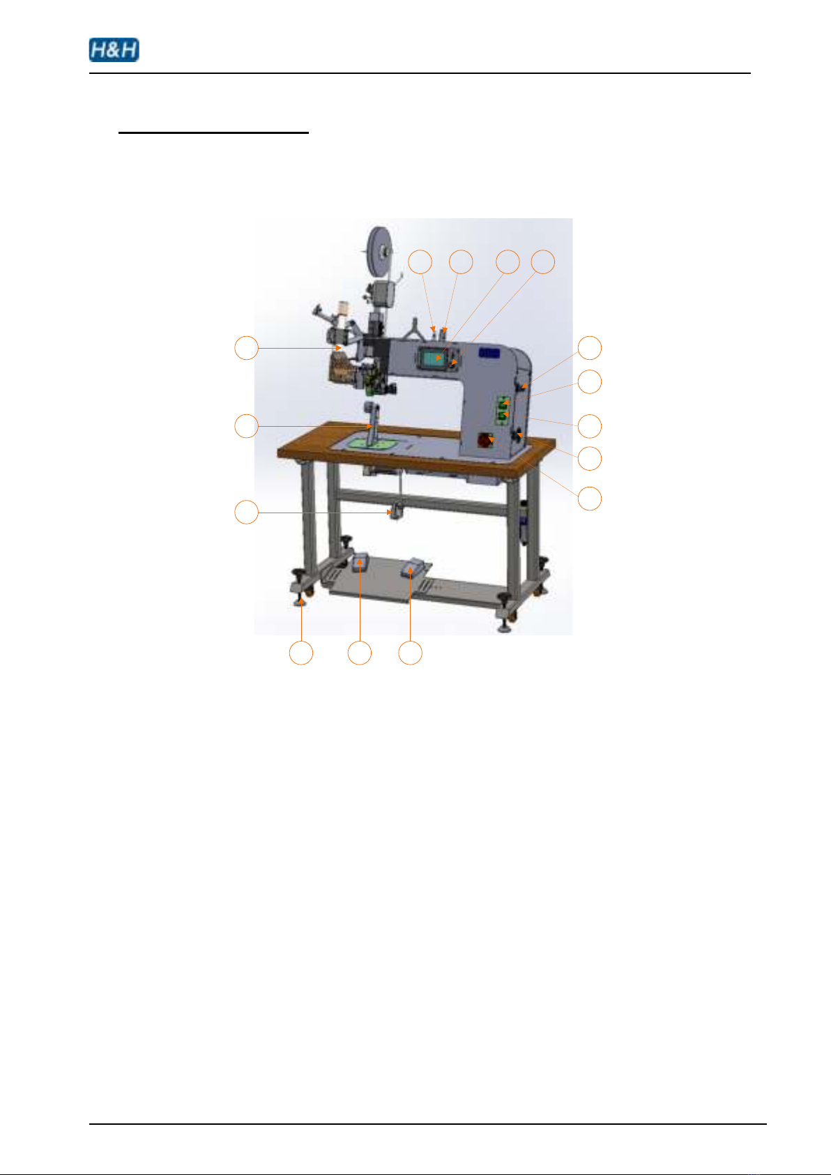
Component Names
Front View
54 6
3
2
1
15 14 13 12
11
10
9
8
7
Figure 2 Front View
1. heater
2. lower pedestal
3. knee switch
4. adjustable floor stand
5. left foot pedal
6. right foot pedal
7. main power switch
8. roller pressure regulator
9. roller pressure gauge
10. nozzle air pressure gauge
11. nozzle air pressure regulator
AI-118 operation manual
issue 1 19.10.07 display version 07 . plc controller version 07 P. 10 of 50
12. key lock
13. touch screen control panel
14. heater power outlet
15. nozzle air intake connector
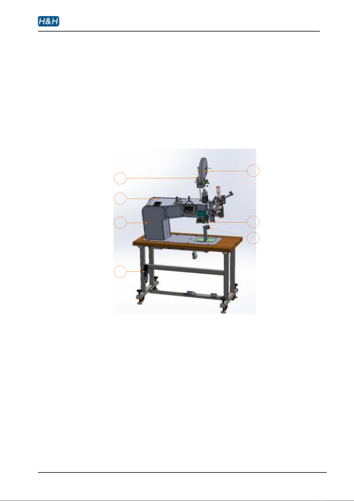
Back View
4
3
2
1
7
6
5
Figure 3 Back View
1. Water filter
2. The main electrical box
3. The main frame
4. Tape tensioner
5. Tape spool
6. Upper roller
7. Lower roller
AI-118 operation manual
issue 1 19.10.07 display version 07 . plc controller version 07 P. 11 of 50
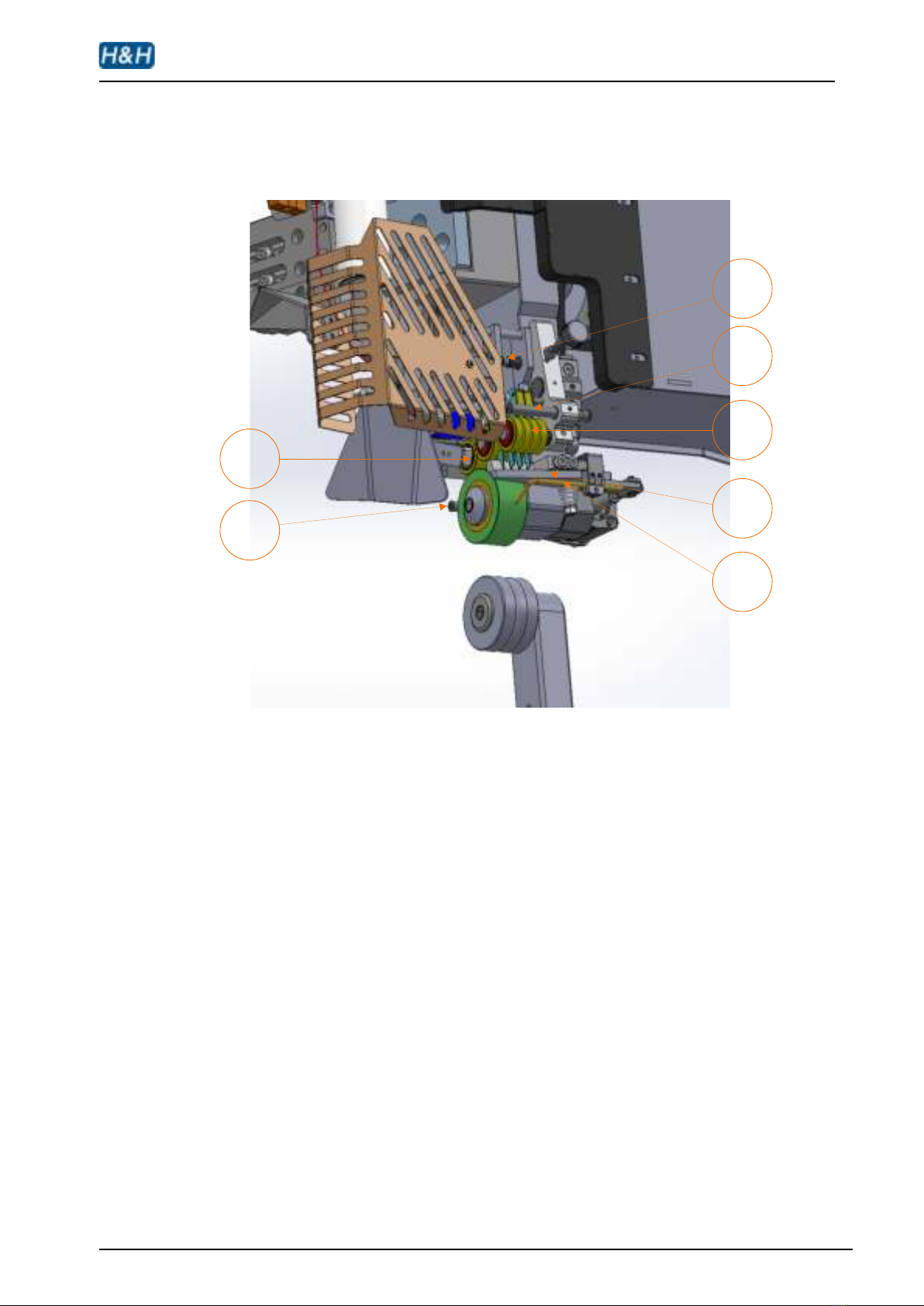
Cutter Assembly
1
2
3
4
5
6
7
Figure 4 Cutter Assembly
1. small tape clamping cylinder
2. the back blow hole
3. the front blow hole
4. cutter blade
5. presser roller
6. tape dropping blow hole
7. tape stabilizer

AI-118 operation manual
issue 1 19.10.07 display version 07 . plc controller version 07 P. 12 of 50
Heater Component - 1
1
2
3
4
Figure 5 Heater Component -1
1. swing cylinder
2. heater fixture
3. temperature sensor
4. safety cover
Heater Component - 2
12
Figure 6 Heater Component -2
1. the heat deflector
2. nozzle

AI-118 operation manual
issue 1 19.10.07 display version 07 . plc controller version 07 P. 13 of 50
Principle of Seam Sealing
The adhesive glue on the seaming tape will become vivid after heating up, let it
place on the seaming sections of different clothes can bind them up like bonding after
cooling down. That bonding can refrain from water seeps in under a certain pressure.
A hot air machine, like AI-118, produces hot air with precisely controlled
temperature to directly heat up the adhesive glue of seaming tape. Fabrics and the
double faced adhesive tape will be sent into two corresponding positions between the
slewing upper and lower rollers. The linear speed of the press rollers is also called the
fringe pruning or double-side tape positioning speed.
During sealing, hot air is blowing out from the nozzle. The hot air that actually
reaches the surface of the tape is a mixture of hot air from the nozzle and the
surrounding air from the proximity. Hence the actual temperature that reaches on the
tape is lower than the original nozzle temperature. The farther the distance between
the nozzle and the tape, the higher the percentage of surrounding air slips in. On the
other hand, a higher hot air flow rate will reduce the percentage of surrounding air
causing the hot air temperature appears on the tape to be higher. So both the nozzle
position and hot air flow rate are the most important factors for temperature control.
In general, the major factors that can affect the seam sealing are as follows:
Hot air temperature
Positioning speed
Nozzle air pressure
Air flow rate
Nozzle position
For a consistent product, the combination of the above factors have to be set
precisely since their effects towards a proper sealing are all interconnecting.
AI-118 operation manual
issue 1 19.10.07 display version 07 . plc controller version 07 P. 14 of 50
Preparation for Installation
Installation must be carried out by authorized personnel. Follow the steps below:
1. Position the machine on a flat surface and allow at least 50cm clearance on both sides as
well as the back side, this is essential for the hot air ventilation and also to allow enough room
for maintenance personnel to carry out necessary service and maintenance
2. Adjust the foot stand so that the machine is level and stable.
3. Loosen all packing cable ties and materials in order to free up all machine movements.
4. Connect the power plug to a suitable outlet with 220V, 16A capacity.
5. Locate the air hose supplied with the machine. Connect one end to the inlet of the
compressed air water filter at the back side of the machine; connect the other end to a
compressed air supply such as air compressor or central air supply. Make sure the
compressed air supply has at least 0.6 Mpa (6 bar) of pressure and a flow rate of not less
than 100L/min.
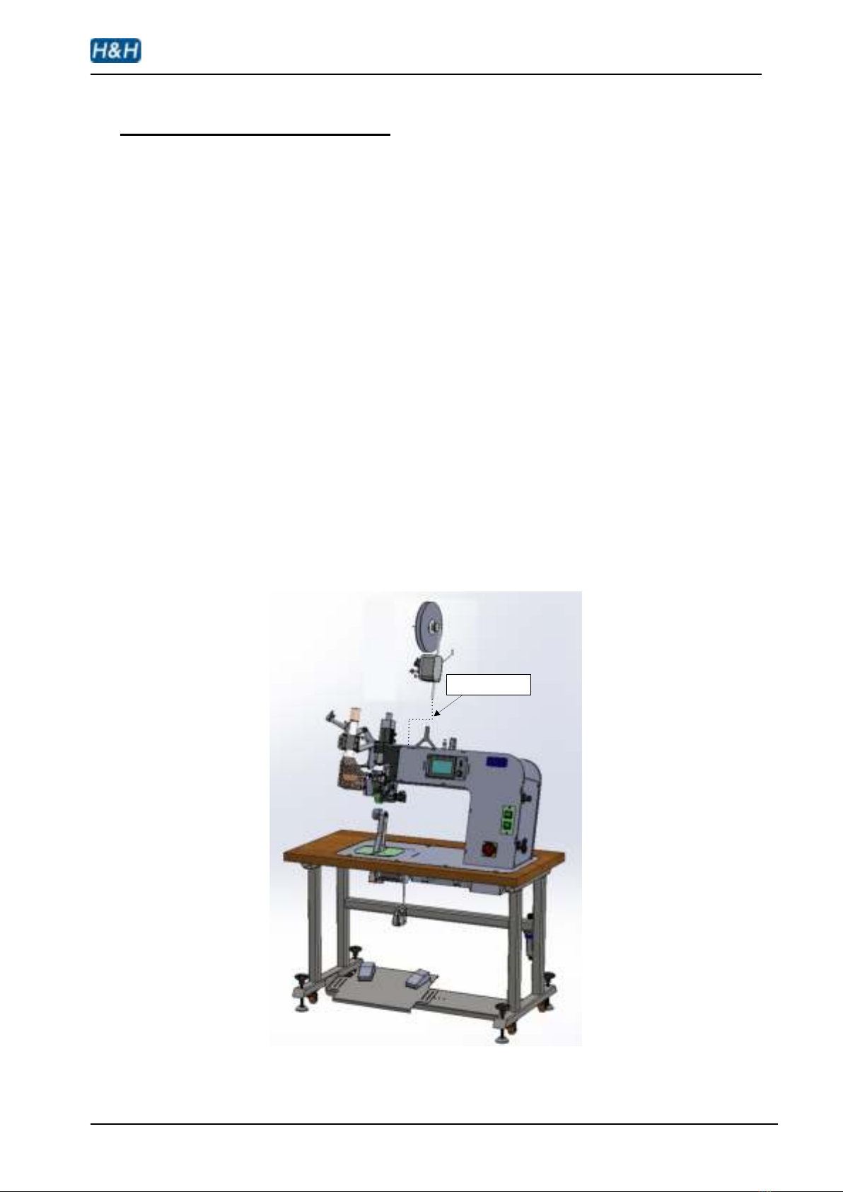
6. Install the tensioner at the top of the machine and align the tape spool at right angle to the
working table of machine. (see diagram below)
fix the tensioner
Figure 7 Fix the Tensioner
AI-118 operation manual
issue 1 19.10.07 display version 07 . plc controller version 07 P. 15 of 50
7. Install a roll of seaming tape with the adhesive side facing the operator (refer to the section
on tape feeding).
8. The machine is ready for operation now.
9. Power on. The touch screen panel will on and showing the program loading page. After a
while, it will change to show the main control page.
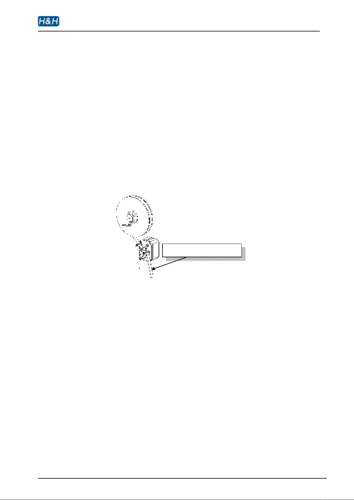
Install tape
Install the tape on the reel and pass the tape through the tape dispenser according
to the established route, as the picture shown below, and with the adhesive side facing the
operator.
Figure 8 Install Tape
Sticky facing the operator

AI-118 operation manual
issue 1 19.10.07 display version 07 . plc controller version 07 P. 16 of 50
Operation & Controls
Touch Screen Control
The welcome note & program loading pages will show up once the machine is
powered on.
welcome note program loading
Figure 9 Booting Page
You can input the parameters via the touch screen control panel only as a matter with
a fingertip. Most of the setting and time control parameters can input onto the panel and
change to different pages for different settings. The surface of the panel is covered with a
membrane for protection. It can well protect the panel from gentle scratching.
Nevertheless, we still recommend a careful and soft touch on it.
Warning: Do not attempt to use scissors, awl, needle, etc. to direct contact with it or a permanent
damage will cause.
AI-118 operation manual
issue 1 19.10.07 display version 07 . plc controller version 07 P. 17 of 50
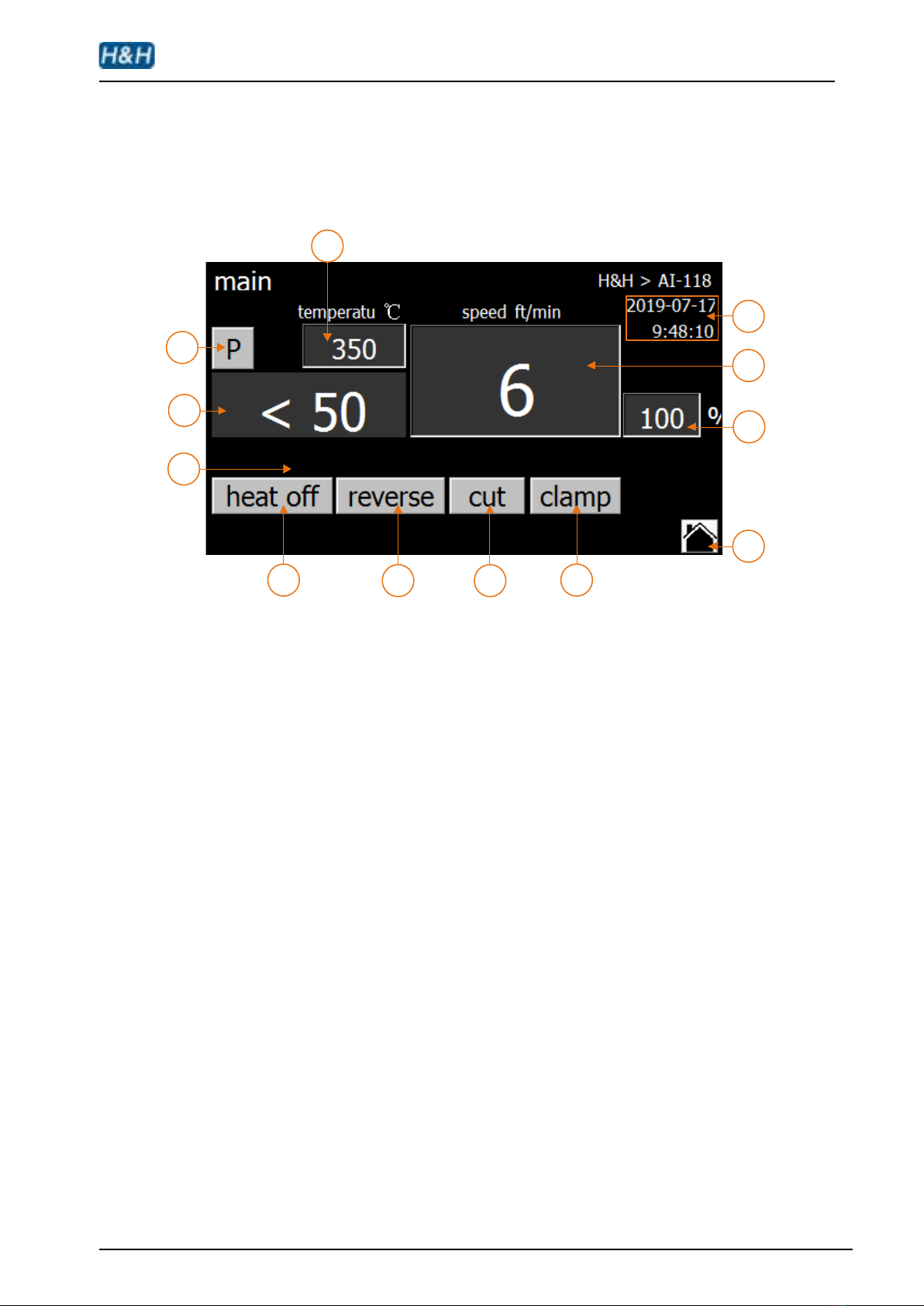
Main page - 1 (page introduction)
The page of the panel is named “main” which means it is the main control of the
machine.
1
2
3
4
56 7 8
9
10
11
12
Figure 10 Main Page - 1
1. Heating temperature setting button & display,press to set temperature, the
setting range is 50-800.
2. When the button changed to red, the nozzle will go to the working position, and
the machine will be locked. After the lock, the machine will not work for safety
protection. This button is used to adjust the position of nozzle. After the wind
nozzle position is adjusted, you need to lift this button or else the machine cannot
work.Note: This function can only be used when the temperature is less than
50 °C.
3. Nozzle temperature feedback (real time temperature feedback). It will display “<
50”, when the temperature less than 50℃. Make sure the temperature is less
than 50℃when you turn off the power supply and compressed air.
4. This data will display if you turn on the “power save” button. If the device is
heating and there is no operation, the countdown is performed here, and the
heater will automatically turn off when the time is up; if there is any operation
during the countdown, the countdown will restart.

AI-118 operation manual
issue 1 19.10.07 display version 07 . plc controller version 07 P. 18 of 50
5. Nozzle heating on/off button (text will turn red when the heater is on).
6. When the pedal is not triggered, press the reverse button to start reversing the
rollers, release and it will stop. It is used to withdraw the tape or remove material
that may be stuck on the upper and lower wheels.
7. To active the cutter. Tape feed will automatic start after cutting off the tape.
8. Press this button to toggle between clamping and loosening of the clamp cylinder,
used to adjust or wear the tape.
9. Next page button. Turn to “main function” page.
10. Adjust the speed ratio between the upper and lower rollers to create a speed
difference; the speed of upper roller is fixed.
When the set value is more than 100, the speed of lower roller is faster than the
speed of upper roller, which is used when the fabric is elastic.
When the set value is less than 100, the speed of lower roller is slower than the
speed of upper roller, which is used when the fabric is not elastic.
When the set value is 100, the speed of the lower roller is equal to the speed of
the upper roller, which is used for general conditions.
11. Roller speed display & setting button (3.3 ft≈1 m).
12. Current time and date displayed.
AI-118 operation manual
issue 1 19.10.07 display version 07 . plc controller version 07 P. 19 of 50
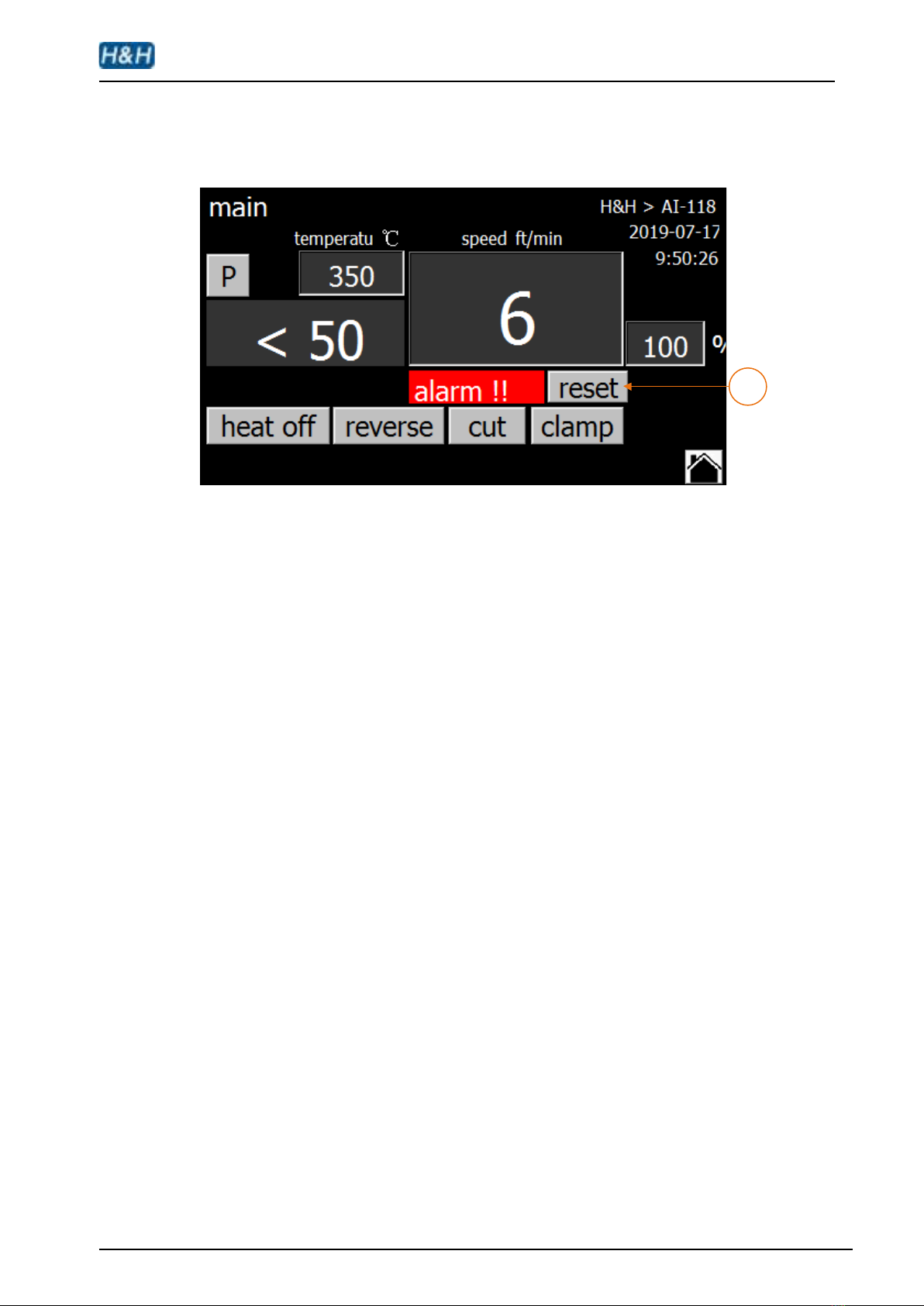
Main page - 2 (page introduction)
1
Figure 11 Main Page - 2
1. An alarm will display when there is/are any fault or beyond the parameter setting
range. After repairing the alarm, click the reset button to the right of the alarm flag
to reset the alarm information.
Table of contents
Other H&H Food Saver manuals


