MELAG MELAseal 200 User manual

Dear Dr.
We should like to extend our thanks for the expression of trust in our company which you have displayed through the
purchase of this sealing device.
Since 1951 MELAG, a medium-sized family-run enterprise, has specialised in the sector of hygiene for medical practices.
In the meantime our company has grown into one of the world's leading producers of sterilization equipment. World sales
of more than 450,000 MELAG devices give testimony to the quality of our products, which we manufacture exclusively in
Germany.
This device was manufactured and checked according to strict quality criteria.
MELAG – management and employees
Operating Manual
MELAseal®200
Bar sealer
Software version 1.12

General notes
Please read this operating manual carefully before commissioning the sealing device. The functionality and value-
retention of this sealing device depends on the care accorded to it.
The instructions include important safety information. Please read the safety information carefully before using the
sealing device.
Please store this operating manual carefully and in close proximity to your sealing device. It represents a component of
the product.
About this manual
Symbols used
Symbol
Explanation
Indicates a dangerous situation, which if not avoided, could entail slight to life-threatening
injuries.
Draws your attention to a situation, which if not avoided, could result in damage to the
instruments, the practice fittings or the device.
Draws your attention to important information.
Formatting rules
Symbol
Explanation
OPEN
Words or phrases appearing on the display of the sealing device are marked as display
text.
see Chapter 2
Reference to another text section within these instructions.
Fig. 1/(3)
Reference to a detail in a figure – in the example, to part no. 3 in figure 1.

Table of contents
Table of contents
Chapter 1 – Performance Specifications.........5
Intended Use............................................................... 5
Chapter 2 – Device description.......................6
Scope of delivery......................................................... 6
Views of the device...................................................... 6
Status display and acoustic signals............................. 7
Chapter 3 – Commissioning............................8
Transport and storage ................................................. 8
Conditions of storage and installation.......................... 8
Requirements of the installation location..................... 8
Commissioning............................................................ 9
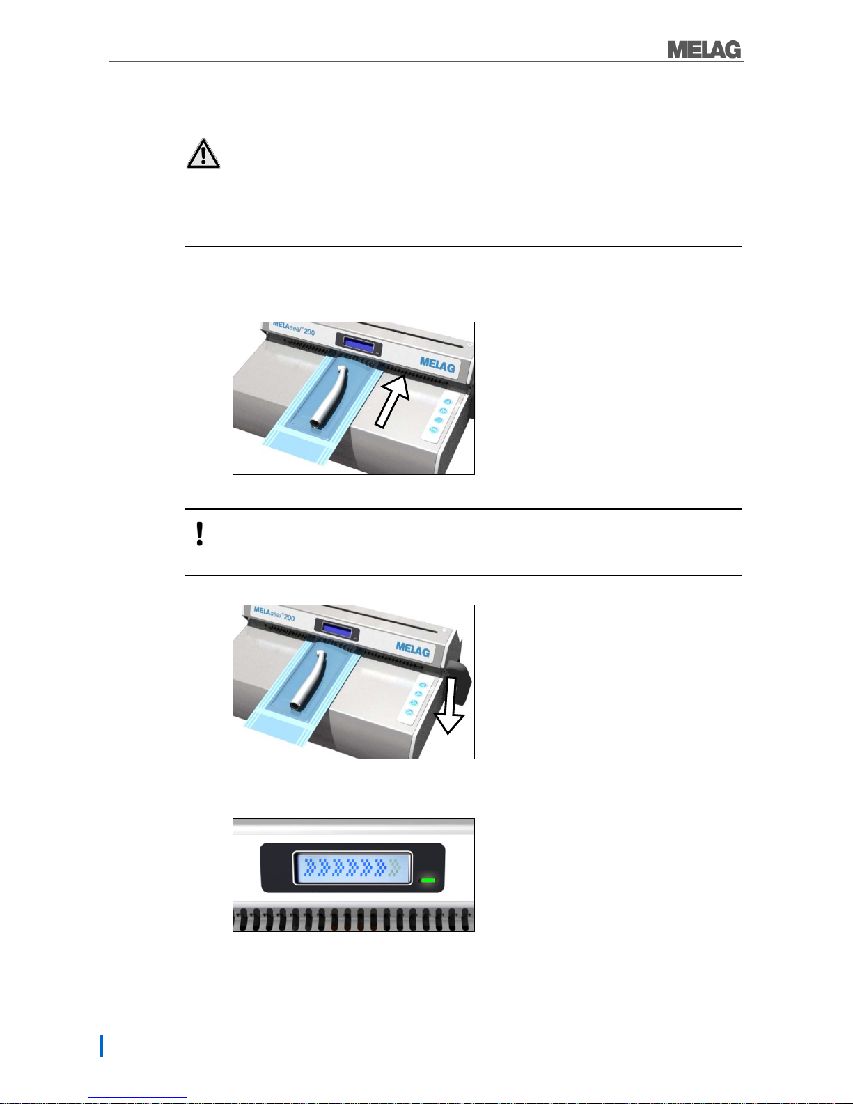
Simple sealing procedure...........................................10
Sealing procedure for roll stock..................................11
Seal seam width.........................................................13
Chapter 4 – Settings .....................................14
Menu structure............................................................14
Setting the date and time............................................14
Changing the sealing temperature..............................15
Switching the signal tones on and off.........................16
Selecting between up to 10 users...............................16
Eco Mode and Standby..............................................17
Chapter 5 – Logging .....................................18
Using the USB flash drive as an output medium ........18
Using the computer as an output medium..................19
File names and ending...............................................19
Reading logs correctly................................................20
Chapter 6 – Optional Accessories.................21
Roll dispenser “standard”............................................21
Roll dispenser "comfort" and "deluxe" ........................21
Wall-mounted roll dispenser.......................................22
Chapter 7 – Maintenance..............................23
Pause times................................................................23
Replacing the blade....................................................23
Cleaning and regular controls.....................................24
Maintenance...............................................................24
Validation....................................................................24
Software update .........................................................24
Chapter 8 – Malfunctions..............................26
Manufacturer's Recommendation for Routine
Operation......................................................28
DIN Specifications........................................30
Terms.........................................................................30
General information regarding the packaging and
sealing procedure.......................................................30
Seal seam width.........................................................30
Clearance of the seal seam to the cutting edge.........30
Strength of seal seam................................................30
Storage length for sterile medical products................31
Accessories and Spare Parts .......................32
Technical Data .............................................32

Chapter 1 – Performance Specifications
4
Safety Instructions
When operating the sealing device, please observe the following safety instructions as well as those
contained in subsequent chapters.
Cable and mains socket
Only the power cable included in the scope of delivery may be connected to the sealing device.
Liquids may not be permitted to reach the interior of the sealing device. This could result in an
electrical shock or short circuiting.
Repair
Never open the housing of the sealing device. Incorrect opening and repair can compromise
electrical safety and pose a danger to the user.
The guarantee and warranty are forfeited as soon as the sealing device is opened by anyone
other than a member of a MELAG-authorized technical customer service.

Chapter 1 – Performance Specifications
5
Chapter 1 – Performance Specifications
Intended Use
This sealing device is designed for application in a medical context, e.g. clinics and medical and dental
practices. It was especially developed for the heat sealing of instruments in sterilization packaging and
complies with the standards DIN EN ISO 11607-2 and DIN 58953 part 7.
Suitable materials
It is suitable for the heat sealing of instruments in transparent sterilization packaging in accordance with
DIN EN 868-5 e.g. MELAfol. Should you wish to use any other packaging materials as those named
above, please consult your stockist first or contact MELAG directly.
Unsuitable film and materials
Pure hose film (double-sided film), as these types tend to become glued together, and can restrict the
functionality of the sealing device.
Polythene film
Soft PVC film
Hard PVC film
Polyamide film
Polypropylene film
PLEASE NOTE
The use of unsuitable packaging materials carries the risk of damage to or malfunction of
the device.
Please observe the manufacturer information regarding the respective packaging materials
as well as the recommended sealing temperatures.

Chapter 2 – Device description
6
Chapter 2 – Device description
Scope of delivery
Please check the scope of delivery before setting up and connecting the sealing device.
Standard scope of delivery
1x MELAseal 200 bar sealer
1x power cable
1x lever
1x MELAG USB flash drive
1x Torx key for the fastening screws of the rear housing cover
1x Operating manual
1x Declaration of conformity
1x Guarantee
1x Test and calibration protocol
Views of the device
Fig. 1: Views of the device
(1) Knife handle (6) Socket for power cable
(2) Display with control lamp (7) USB interface (type B) for connection to the
computer
(3) USB interface for the USB flash drive (8) 4 Softkeys
(4) Square hole for lever (double-sided) (9) Lever
(5.1/5.2) Bracket for roll dispenser (10) Power switch
(1)
(2)
(3)
(4)
(6)
(9)
(10)
(5.1)
(5.2)
)
(7)
(8)

Chapter 2 – Device description
7
Status display and acoustic signals
Table 1: The meaning of the control lamps and signal tones
Control lamp/
acoustic signals
Possible cause
Measure
●
LED illuminates
orange
Sealing device is in the heating-
up or cooling down phase
Please wait until the pre-set sealing
temperature has been reached.
☼
LED flashes red
Warning signal
sounds
The lever is depressed during
the heating phase, the sealing
temperature has not yet been
reached.
Clear the display message with and wait
until the LED control lamp illuminates green
permanently.
The lever has been raised
early, despite the required
sealing time not having been
reached.
Clear the display message with . Leave
the lever depressed until the message Open
is issued.
The lever has not been raised,
despite the required sealing
time having been completed.
Raise the lever as soon as the display
message Open is issued. Otherwise, the
sealing procedure will not be completed
successfully. Failure to observe these
provisions can result in the melting of the film
and damage to the sealing device.
●
LED illuminates green
The sealing device has reached
the pre-set sealing temperature
and is ready for operation.
The pre-set sealing time (c. 3
sec) has been reached and the
sealing procedure has been
ended.
Raise the lever and remove the packaging.
☼
LED flashes green
The sealing procedure runs
when the lever is depressed (3
secs). The progress bar will be
displayed.
Wait until the green LED control lamp is
constantly illuminated / the display outputs
Open.
●
LED illuminates red,
Warn signal sounds
(malfunction)
Device fault: The heating phase
is taking too long (> 5 min.); the
sealing device cannot reach the
pre-set sealing temperature.
Switch off the sealing device and then back
on again.
Upon repeated occurrence, inform your
stockist / MELAG customer services.

Chapter 3 – Commissioning
8
Chapter 3 – Commissioning
Transport and storage
WARNING
The use of unsuitable packaging can result in damage to the housing and the device
interior.
The sealing device should only be transported in its original or otherwise suitable packaging.
Storage
The device should be stored in such a way to protect against humidity.
Conditions of storage and installation
In accordance with current VDE specifications, the sealing device is unsuitable for operation in areas
exposed to the danger of explosion.
The sealing device is conceived for use outside patient surroundings. The device should be located a
minimum of 1.5 m radius away from the treatment area.
Observe all the information contained in this chapter during commissioning.
DANGER!
Failure to comply with the set-up conditions can result in malfunctions or damage to the
sealing device and/or human injury.
Requirements of the installation location
Install the sealing device in a dry and dust-protected location.
Maintain sufficient clearance to the surrounding surfaces in order to ensure sufficient ventilation.
Ensure that the sealing device is located away from direct sunshine and outside the range of other
sources of heat.
The sealing device must be protected against blows or vibration.

Chapter 3 – Commissioning
9
Commissioning
Connecting the sealing device
Check the following points before connecting:
The device power switch is on.
Use only the network cable included in the scope of delivery.
The USB flash drive included in the scope of delivery is plugged into the sealing device.
1. Connect the low-heat power socket of the power cable to the rear side of the sealing device and
connect the power plug in the power socket.
2. Insert the lever in the square hole on the left or right hand side of the device as required.
Switching on the sealing device
1. Switch on the sealing device at the mains switch
After activation, the display issues system information e.g. the user set, confirmation as to
whether the USB flash drive is connected correctly and the current temperature. The control lamp
on the front of the sealing device illuminates orange and the sealing device is heated to the pre-
set temperature.
The sealing device is ready for operation as soon as the pre-set sealing temperature has been
reached and the display changes between Ready and an output of the current temperature and
time. The control lamp must also illuminate continuously green.
Ready

Chapter 3 – Commissioning
10
Simple sealing procedure
DANGER
The sealing bar is heated continuously after the sealing device has been switched on. The
surrounding metal components are hot!
Contact with the hot metal parts can result in burns.
Never touch the metal surfaces on the cutting bar or in the area of the rear and fore paper
guide directly.
In order to perform a simple sealing procedure, proceed as follows:
1. Introduce the packaging in the paper guide with the film side facing upwards and push the
packaging through the pressure bar and sealing bar. Ensure maintenance of the correct
clearance between the instrument and seal seam (consult the section DIN Specifications).
WARNING
The film side of the packaging must always face upwards. Should the packaging be inserted
incorrectly, this could result in the deposit of film residue on the sealing rail.
2. Press the lever forwards to its fullest extent until it snaps.
3. Leave the lever depressed as long as the progress bar in the display completes and the control
lamp flashes green in short intervals (for 3 seconds).
4. When the display switches to Open and the control lamp is continually illuminated green again,
return the lever (up) to its starting position.

Chapter 3 – Commissioning
11
The sealing procedure has been completed successfully.
If the USB flash drive has been connected, a log will automatically be generated and saved on the
USB flash drive.
If a USB flash drive has not been connected, the most important sealing parameters will be
displayed alternately up to 4 times. Then the display returns to Ready.
Sealing procedure for roll stock
DANGER
The sealing bar is heated continuously after the sealing device has been switched on. The
surrounding metal components are hot!
Contact with the hot metal parts can result in burns.
Never touch the metal surface on the cutting bar and in the area of the rear and fore paper
guide directly.
Cutting the film
If the instruments are packaged from the roll in transparent sterilization packaging bags, proceed as
follows:
1. Introduce the film in the paper guide from the rear with the paper-side pointing downwards
(lower slit) and slide the film forward between the pressure and sealing bar up to the desired
length.
2. Press the lever forwards to its fullest extent until it clicks.
Open

Chapter 3 – Commissioning
12
3. Leave the lever depressed as long as the progress bar in the display completes (for 3 seconds).
4. Ideally, the film should be cut off during the sealing procedure. Move the knife to the other end of
the sealing device quickly; the lever should remain depressed. Do not return the knife handle.
5. If the display switches to Open and the control lamp illuminates continuously green, raise the
lever and remove the film bag thus produced.
Sealing film bags
To seal on the corresponding length, proceed as follows:
1. Place the instrument in the film bag thus produced. Ensure maintenance of the correct clearance
between instrument and seal seam (consult the section DIN Specifications).
2. Slide the open side of the bag from the front into the paper guide.
Open

Chapter 3 – Commissioning
13
WARNING
The film side of the packaging must always face upwards. Should the packaging be inserted
incorrectly, this could result in the deposit of film residue on the sealing rail.
3. Press the lever forwards to its fullest extent until it clicks.
4. Leave the lever depressed as long as the progress bar in the display completes (for approx. 3
seconds).
5. When the display changes to Open and the control lamp is continually illuminated green again,
return the lever (up) to its starting position.
6. The sealing procedure has been completed successfully.
PLEASE NOTE
When sealing MELAfol sealing bags with lateral creases, please observe and comply with the
special information contained in the sealing bag operating manual regarding sealing cassettes.
Seal seam width
The sealing device produces homogeneous seal seams of 10 mm in width with every sealing procedure.
The recommended nominal size for the width of the seal seam in the German standard DIN 58953 part 7
is only 6 mm.
Section 4.3.2 of DIN EN 868-5 requires a min. total seal width of 6 mm. The sum of the
individual seams should amount to min. 6 mm
Open

Chapter 4 – Settings
14
Chapter 4 – Settings
Menu structure
├
Standard display output
Key:
│
└
Display of temperature/time/ready
├
User
User
│
├
User 01
User 01
│
├
User 02
User 02
│
├
…
…
│
└
User 10
User 10
├
Settings
Settings
│
├
Temp
Sealing temperature
│
├
Tone
Signal tones
│
├
Time
Time
│
├
Date
Date
└
Eco Mode
Eco Mode
└
Info
Information
├
Seal Cnt
Counter for the sealing procedures
├
Svc Date
Date of the next service
├
Svc Cnt
Counter until the next service
├
Version
Software version
└
S/N
Serial number
Pressing the keys or. repeatedly enables navigation to the ring menu.
Pressing returns you to the next highest menu level.
Setting the date and time
NOTE
The date and time must be set correctly so that the time of the sealing procedure can be logged
correctly and a clear allocation to the time of sealing can be generated.
Time
To set the current time, proceed as follows:
1. Switch on the sealing device at the power switch and wait until the temperature is issued on the
display.
2. Press twice in order to navigate to Settings.
3. Press to navigate to the Settings menu. The display changes to Temp.
4. Press twice to navigate to the Time option.
5. Press to confirm. The hour display flashes.
6. Press or to change the hours forwards or backwards.

Chapter 4 – Settings
15
7. Press to save the settings. The minute display will now flash.
8. Press or to change the minutes forwards or backwards.
9. Press to save the settings. The display no longer flashes.
10. Press repeatedly to leave the menu (press three times start display).
Date
NOTE
The date will be displayed in the English date format (YY-MM-DD).
To set the current time, proceed as follows:
1. Switch on the sealing device at the power switch and wait until the temperature is issued on the
display.
2. Press repeatedly in order to navigate to Settings.
3. Press to navigate to the Settings menu. The display changes to Temp.
4. Press to navigate to the Date option.
5. Press to confirm. The first value (year) flashes.
6. To alter the year, month and day, proceed in a way similar to setting the time.
Changing the sealing temperature
To alter the set sealing temperature proceed as follows:
1. Switch on the sealing device at the power switch and wait until the temperature is issued on the
display.
2. Press repeatedly in order to navigate to Settings.
3. Press to navigate to the Settings menu. The display changes to Temp.
4. Press to confirm. The display flashes.
5. Press or to increase or decrease the sealing temperature.
6. Press to save the value.
7. Press repeatedly in order to leave the menu.
PLEASE NOTE
The extent to which individual components in the sealing device expand is altered upon
temperature changes. This also influences the sealing force. To this end, the sealing force
thresholds are automatically adapted to the changed sealing temperature.

Chapter 4 – Settings
16
Switching the signal tones on and off
In order to switch off the signal tones where necessary, proceed as follows:
1. Switch on the sealing device at the power switch and wait until the temperature is displayed on
the display.
2. Press repeatedly in order to navigate to Settings.
3. Press to navigate to the Settings menu. The display changes to Temp.
4. Press to navigate to the Tone option.
5. Press to confirm. The display flashes.
6. Press or to switch the signal tones on or off.
7. Press to save the settings.
8. Press repeatedly in order to leave the menu.
Selecting between up to 10 users
In order to guarantee exact traceability over every sealing procedure, you can select the respective user
before sealing. Proceed as follows:
1. Switch on the sealing device at the power switch and wait until the temperature is displayed on
the display.
2. Press repeatedly in order to navigate to User.
3. Press to confirm. The display flashes.
4. Press or to select from up to 10 users.
5. Press to save the settings.
The display returns to the initial state.
We recommend that you draw up an overview in your QM documents from which you can find the
allocation of each user in MELAseal 200.
Example:
The name of the trained
member of staff
User name in MELAseal®200
Signature
Ms
User 01
Ms
User 02

Chapter 4 – Settings
17
Eco Mode and Standby
The MELAseal 200 is equipped with a two-stage energy-saving function.
Eco mode: If the lever or keys are not activated within 15 minutes after the sealing device has been
activated (Ready Mode), Eco Mode will be activated, i.e. the temperature will be reduced by 40°C.
Activate one of the key in order to return to Ready Mode.
The sealing device is ready to operate after a short time.
Standby: If the lever or keys are not activated within 30 minutes after the sealing device has been
activated (Ready Mode), the device switches to Standby, i.e. the heating and display are deactivated. The
illuminated LED control lamp shows that the sealing device is still activated.
Activate one of the key in order to return to Ready Mode. The sealing device is ready to operate after c. 2
min.
In order to switch off this function, proceed as follows:
1. Press repeatedly in order to navigate to Settings.
2. Press to navigate to the Settings menu. The display changes to Temp.
3. Press to navigate to the Eco mode.
4. Press to confirm. The display flashes.
5. Press or to switch the Eco mode on or off.
6. Press to save the settings.
7. Press repeatedly in order to leave the menu.
The display returns to the initial state.
PLEASE NOTE
The Eco mode and standby are always switched off together. It is not possible to switch off the
Eco mode or Standby separately.

Chapter 5 – Logging
18
Chapter 5 – Logging
DIN EN ISO 11607-2 requires that the sealing process be monitored and documented in order to satisfy
the requirement for compliance with the specifications contained in part 2 of the standard.
As a result, you are able to record the logs of the seal runs and output and archive them on the following
output media:
USB flash drive
Computer with documentation software, e.g. MELAtrace/MELAview from software version 3
If a computer or USB stick is not connected, the most important sealing parameters can also be
documented by hand. The sealing parameters are displayed alternately up to 4 times.
Using the USB flash drive as an output medium
WARNING
Inappropriate handling can result in damage to the USB flash drive, the USB interface and
data loss.
Do not exert any force on the USB flash drive whilst inserting it.
Do not place any objects on the inserted USB flash drive.
A USB flash drive will be delivered with every sealing device as standard.
Should you wish to save the log of a sealing procedure on the USB flash drive automatically, connect it as
follows:
1. Switch off the sealing device.
2. Insert the USB flash drive in the USB interface on the left-hand side of the sealing device.
3. Switch on the USB flash drive. As soon as the USB flash drive has been recognized and is ready
for operation, the display will show Mem_Conn (=memory connected).
PLEASE NOTE
Always switch off the sealing device before connecting or removing the USB flash drive.
If the USB flash drive has been reformatted, it must be issued with a name.
Save the log files on the computer at regular intervals.
Select only a single logging type, either by USB flash drive or via MELAtrace/MELAview.
Otherwise, this can result in a failure to recognize that the output media has been
disconnected, which can result in data loss.
Do not save any further non device-relevant files on the USB flash drive.

Chapter 5 – Logging
19
Using the computer as an output medium
The following conditions must be fulfilled in order to use the computer as an output device:
The computer is equipped with an USB interface.
A MELAG USB driver is installed on the computer.
The documentation software MELAtrace/MELAview (from software version 3) is installed on the
computer.
The sealing device is connected to the computer via a USB cable (art.-no. 19902, optionally
available).
Proceed as follows to connect the sealing device to a computer:
1. Install the MELAseal 200 PC driver on your computer. The driver can be downloaded from the
download centre on the MELAG Website (www.melag.de/service/download-center/pc-
anwendungen/MELAview).
2. Connect the type B USB connector of the USB cable to the rear of the sealing device and connect
the other end to the computer. Please use MELAtrace/MELAview (from software version 3) to
record the logs.
3. Establish a connection between the documentation software and the sealing device and
determine the folder in which the sealing logs are to be archived. Further information relating to
the operation of the sealing device with the documentation software can be found in the
corresponding operating manual.
PLEASE NOTE
The daily log is continued even if the sealing device is switched on and off; i.e. a new log will not
be started.
File names and ending
The log is stored in HTML format (in English).
The file name consists of the actual date, the serial number of the sealing device and the total counter.
20130723_132000901_0000095.htm
Date
Serial number
Total counter

Chapter 5 – Logging
20
Reading logs correctly
A log includes all printing procedures of one day. A row in the log is written for every sealing procedure.
If a malfunction occurs during a sealing procedure, this is recorded in the log by a fault number, e.g. F4.
The corresponding fault value (e.g. sealing temperature, or force) will, depending on the nature of the fault,
be displayed in square brackets or no value will be displayed.
Example of a log of multiple sealing procedures
--------------------
MELAG MEDIZINTECHNIK
--------------------
10 MELAG MELAseal 200
15 Date: 2014-08-14
20 S/N: 132000901
25 Ver: V1.12
30 Op.Hrs: 0000102
35 Svc.Date: 2015-02-19
|Stat |Time |Dur |Temp |Force|Limits - Dur, Temp, Force|Usr|SCnt|SvcCnt|TtlCnt |CS
|-----|--------|------|-----|-----|-------------------------|---|----|------|-------|---
|OK |15:23:19| 03.3 | 180 | 211 |03.0-08.0 175-185 170-230|U02|0001|049820|0000180|031
|OK |15:23:30| 03.3 | 177 | 211 |03.0-08.0 175-185 170-230|U02|0002|049819|0000181|020
|OK |15:23:38| 03.5 | 177 | 209 |03.0-08.0 175-185 170-230|U02|0003|049818|0000182|043
|F3 |15:23:42|[01.6]| 177 | 209 |03.0-08.0 175-185 170-230|U02|0004|049817|0000183|098
|OK |15:23:50| 03.4 | 179 | 209 |03.0-08.0 175-185 170-230|U02|0005|049816|0000184|054
Key
Row 10 – Designation of the sealing device
Row 15 – Date of the sealing procedure
Row 20 – Serial number of the sealing device
Row 25 – Software version installed
Row 30 – Total operating hours
Row 35 – Date of the next servicing
--------------
Start – OK: Sealing procedure successful
– Warn_01: Warning
– Err_01: Fault number/sealing procedure unsuccessful
Time – Time of the sealing procedure
Dur – Duration of the sealing procedure
Temp – Sealing temperature (in °C)
Force – The force (in N), with which the packaging was sealed
Limits – The threshold range of sealing duration (Dur), sealing temperature (Temp) and force (Force)
Usr – User
SCnt – Daily batch counter for sealing procedures
SvcCnt – No. sealing procedures until the next service
TtlCnt – Total number of the sealing procedures
CS – Coded proof of log authenticity
S/N - Serial number of the sealing device
Op. Hrs. - Total of previous operating hours
Other manuals for MELAseal 200
3
Table of contents
Other MELAG Food Saver manuals
Popular Food Saver manuals by other brands

Minipack-Torre
Minipack-Torre Vision Restyling instruction manual

Chesterton
Chesterton TwinHydrostatic 4410 Installation, Operation and Rebuild Instructions

Advanced Poly-Packaging
Advanced Poly-Packaging T-200 Operation guide

FoodSaver
FoodSaver V2040 series reference guide

LEM
LEM MaxVac 1088 instruction manual

AmazonBasics
AmazonBasics B073DC3282 manual