➤Note:The ailerons are attached to the wing halves
from the factory,but the hinges are not glued in
place. The right aileron must go with the right wing
half and the left aileron must go with the left wing half.
Be sure to mark the aileron for correct identification
and top and bottom before you take it apart from the
wing.
1. Carefully remove the aileron from the right wing
panel by pulling straight out with even pressure.
2. Remove all four hinges from the aileron. Flex the
hinges accordingly so that they move freely.
3. Mix a small amount of 30-minute epoxy. Using either
a mixing stick or an epoxy brush,apply the epoxy
sparingly inside each hinge slot on the aileron.
Additionally,apply a small amount of epoxy to the top
and bottom half of each hinge. Insert the hinges into
the aileron accordingly until the hinge line is even with
the leading edge of the aileron.
4. Wipe off any excess epoxy using a paper towel and
rubbing alcohol.
➤Hint: Lightly coat both ends of the ailerons with
epoxy,if they don’t have covering on them;this will
prevent the ailerons from becoming fuel-soaked. You
can mix a small amount of rubbing alcohol (one part
alcohol to three parts epoxy) into the epoxy to thin
it. This will make for a thinner coat of epoxy which
prevents a thick build-up on the ends of the ailerons.
This is a common way to“fuel proof” bare wood.
5. The bolt holes on each wing half are pre-drilled.
Locate the holes that are under the covering and
carefully cut-out the covering with your hobby knife.
Lightly coat the inside of the holes with your thinned
epoxy. Only use just enough to have a thin coat. Too
much will not allow the wing bolts to pass through.
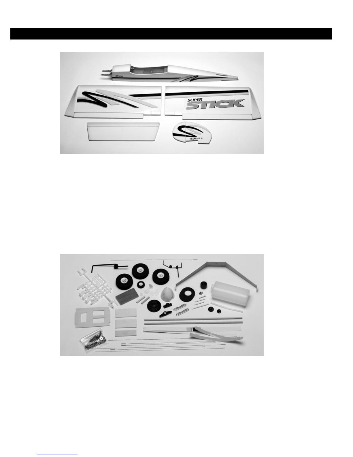
➤Parts Needed
Right wing panel with aileron & hinges
Left wing panel with aileron & hinges
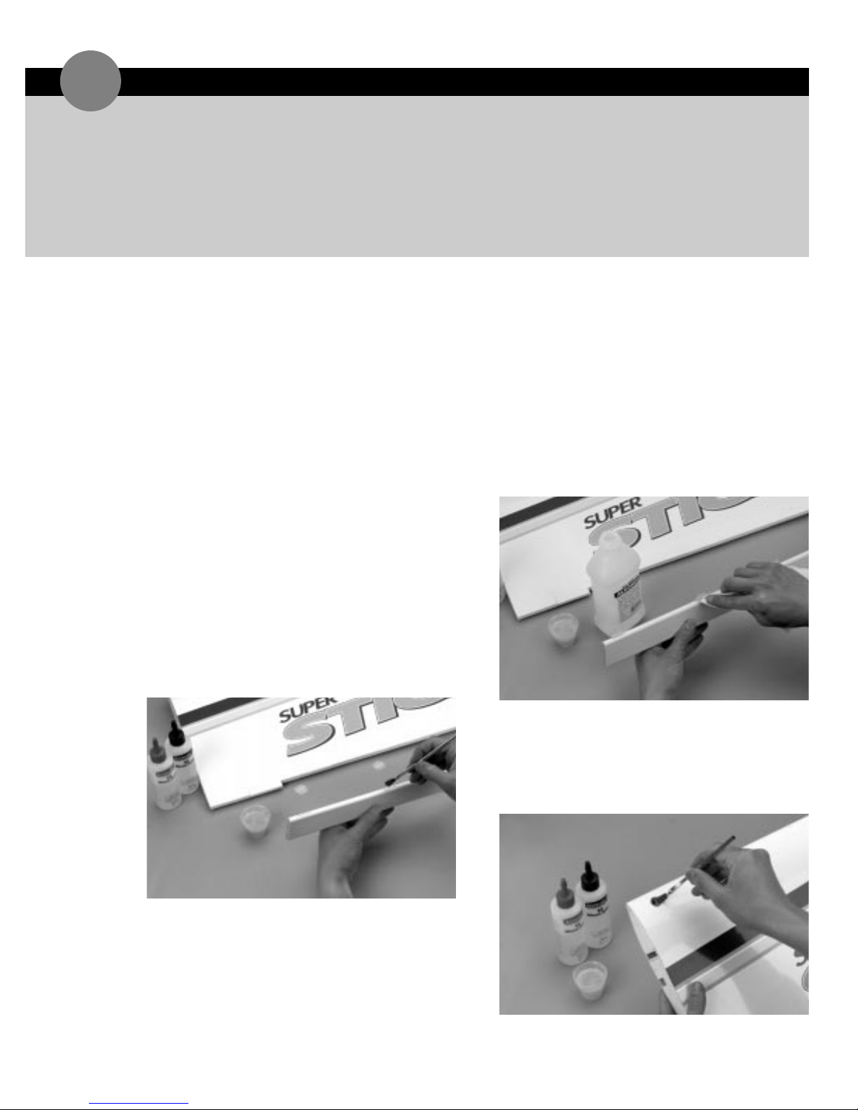
➤Tools &Adhesives Needed
30-minute epoxy
Paper towels
Rubbing alcohol
Mixing stick
Epoxy brush
Ruler
ASSEMBLINGTHEWINGS
1