HANLA HGS-100 User manual

HANLA IMS CO., LTD.
1610-5 SONGJEONG-DONG GANGSEO-GU BUSAN KOREA
-Tel: 82-51-601-3000
-Fax: 82-51-831-1850
-Email: hanla@hanlaims.co.kr
MT-HGS-100NEW SYSTEM
Rev.9
2010-07-13
Page 1/58
HGS-100
TECHNICAL MANUAL
¾Hydrocarbon Gas Sampling & Detection System

HANLA IMS CO., LTD.
1610-5 SONGJEONG-DONG GANGSEO-GU BUSAN KOREA
-Tel: 82-51-601-3000
-Fax: 82-51-831-1850
-Email: hanla@hanlaims.co.kr
MT-HGS-100NEW SYSTEM
Rev.9
2010-07-13
Page 2/58
Table of Contents
1. INTRODUCTION ------------------------------------------------------ 5
1.1. Operating Principle -------------------------------------------------------------------------------------- 6
1.3.1 BLOCK DIAGRAM ------------------------------------------------------------------------------------ 7
1.3. SPECIFICATIONS ----------------------------------------------------------------------------------------- 9
1.3.1. ANALYZING UNIT ------------------------------------------------------------------------------------ 9
1.3.2. CONTROL UNIT -------------------------------------------------------------------------------------- 9
1.4. Technical Data for Each Component ----------------------------------------------------------------- 10
1.4.1. ANALYZING UNIT ---------------------------------------------------------------------------------- 10
1.4.2. A/D Conversion and Alarm ----------------------------------------------------------------------- 10
1.4.3. Communication ------------------------------------------------------------------------------------ 10
1.4.4 Gas detectors -------------------------------------------------------------------------------------- 11
1.4.5. Solenoid valves ------------------------------------------------------------------------------------ 11
1.4.6. flowmeter, regulation valve, filter ----------------------------------------------------------------- 11
1.4.7 Analyzing Unit adjacent equipments ------------------------------------------------------------- 11
1.4.8. CONTROL UNIT ------------------------------------------------------------------------------------ 12
2. OPERATION --------------------------------------------------------- 13
2.1. NORMAL OPERATION MODE ------------------------------------------------------------------------- 13
2.1.1. Before switching power on ----------------------------------------------------------------------- 13
2.1.2. Start-up -------------------------------------------------------------------------------------------- 13
2.1.3. Control Unit's LCD Display arrangement. -------------------------------------------------------- 14
2.1.4. Sampling and Purging sequences ---------------------------------------------------------------- 16
2.2 GAS CONCENTRATION ALARMS ---------------------------------------------------------------------- 18
2.3. SYSTEM ALARMS -------------------------------------------------------------------------------------- 19
2.3.1 Typical system alarm sequence ------------------------------------------------------------------- 19
2.3.2. System Shutdown --------------------------------------------------------------------------------- 19
2.3.3. Flow alarm ----------------------------------------------------------------------------------------- 20
2.3.4 Detector (Gas detector) fault ---------------------------------------------------------------------- 20
2.3.5. Sample leak ---------------------------------------------------------------------------------------- 20
2.3.6 Communication fault ------------------------------------------------------------------------------ 20
2.4. MAIN MENU ------------------------------------------------------------------------------------------- 21
2.4.1 Presentation ---------------------------------------------------------------------------------------- 21

HANLA IMS CO., LTD.
1610-5 SONGJEONG-DONG GANGSEO-GU BUSAN KOREA
-Tel: 82-51-601-3000
-Fax: 82-51-831-1850
-Email: hanla@hanlaims.co.kr
MT-HGS-100NEW SYSTEM
Rev.9
2010-07-13
Page 3/58
2.4.2 General notes -------------------------------------------------------------------------------------- 21
2.5. DISPLAY FUNCTION F1 ------------------------------------------------------------------------------- 22
2.6. ALARM ACKNOWLEDGEMENT F2 -------------------------------------------------------------------- 23
2.7. CHANNEL MENU F3 ----------------------------------------------------------------------------------- 23
2.7.1 Normal mode -------------------------------------------------------------------------------------- 23
2.7.2 Handling mode ------------------------------------------------------------------------------------ 23
2.7.3 Channel Hold function ----------------------------------------------------------------------------- 24
2.7.4 Channel Skip function ----------------------------------------------------------------------------- 25
2.7.5. Acknowledgement function ----------------------------------------------------------------------- 25
2.8 UTILITIES MENU F4 ------------------------------------------------------------------------------------ 26
2.8.1. Gas Detector Status ------------------------------------------------------------------------------- 26
2.8.2. Filter Purge function ------------------------------------------------------------------------------ 26
2.8.3. Channel Purge function --------------------------------------------------------------------------- 26
2.8.4. Leak test ------------------------------------------------------------------------------------------- 26
2.9 COMMAND SUMMARY -------------------------------------------------------------------------------- 27
3.
INSTALLATION AND COMMISSIONING -------------------------- 35
3.1. MECHANICAL CONNECTIONS ------------------------------------------------------------------------ 35
3.2. ELECTRICAL CONNECTIONS -------------------------------------------------------------------------- 36
3.3. COMMISSIONING ------------------------------------------------------------------------------------- 37
3.4 CONFIGURATION MENU F5 --------------------------------------------------------------------------- 37
3.5. DETECTOR SETTING / calibration menu ------------------------------------------------------------- 39
3.5.1. Detector setting mode ---------------------------------------------------------------------------- 39
3.5.2. Detector calibration menu ------------------------------------------------------------------------ 41
3.5.3. Calibration Unit. ----------------------------------------------------------------------------------- 43
3.6. Gas detector for the BALLAST TANK HC(Hydrocarbon) ------------------------------------------- 44
3.7. Gas detector for the PUMP ROOM HC(Hydrocarbon) --------------------------------------------- 46
3.8. Gas detector for the PUMP ROOM O2(Oxygen)---------------------------------------------------- 47
3.9. Gas detector for the PUMP ROOM H2S(Hydrogen Sulphide) ------------------------------------- 48
3.10. CHANNEL SETTING ---------------------------------------------------------------------------------- 49
3.10.1. sampling and purge duration setting ----------------------------------------------------------- 49
3.10.2. Detector 0-7 enable mode (FLOW) ------------------------------------------------------------- 50
3.10.3. Pre-Alarm and Alarm limits setting(GAS) ------------------------------------------------------- 50
3.11. HORN OUTPUT --------------------------------------------------------------------------------------- 51
3.12. TIME SETTING ---------------------------------------------------------------------------------------- 52
3.13. MEMORY CONTROL --------------------------------------------------------------------------------- 52

HANLA IMS CO., LTD.
1610-5 SONGJEONG-DONG GANGSEO-GU BUSAN KOREA
-Tel: 82-51-601-3000
-Fax: 82-51-831-1850
-Email: hanla@hanlaims.co.kr
MT-HGS-100NEW SYSTEM
Rev.9
2010-07-13
Page 4/58
3.14 SYSTEM CHECK USING “HOLD” FUNCTION -------------------------------------------------------- 53
3.14.1. Operating Procedure ----------------------------------------------------------------------------- 53
3.14.2. Sample LINE LEAK TEST using “HOLD” function. ----------------------------------------------- 55
3.14.3. FLOW ALARM TEST using “HOLD” function ---------------------------------------------------- 55
3.14.4. GAS ALARM TEST using “HOLD” function ------------------------------------------------------ 55
3.14.5. SYSTEM SHUTDOWN TEST using “HOLD” function -------------------------------------------- 55
3.15. CHECK OF COMMISSIONING ------------------------------------------------------------------------- 56
3.15.1. CHECK OF INSTALLATION ----------------------------------------------------------------------- 56
3.15.2. CHECK OF POWER SUPPLY AND AIR SUPPLY -------------------------------------------------- 56
3.15.3. CHECK OF VALVES ------------------------------------------------------------------------------- 56
3.15.4. CHECK OF AIR SUPPLY -------------------------------------------------------------------------- 56
3.15.5. AC POWER SUPPLY ------------------------------------------------------------------------------ 56
3.15.6. FLOW setting ------------------------------------------------------------------------------------- 56
3.15.7. CHECK OF BASIC FUNCTION -------------------------------------------------------------------- 57
3.15.8. CHECK OF SYSTEM OPERATION. ---------------------------------------------------------------- 57
3.15.9. Check the FLOW of each channel. -------------------------------------------------------------- 57
3.15.10. CALIBRATION OF GAS DETECTOR. ------------------------------------------------------------- 57
4. TROUBLE SHOOTING ----------------------------------------------- 58

HANLA IMS CO., LTD.
1610-5 SONGJEONG-DONG GANGSEO-GU BUSAN KOREA
-Tel: 82-51-601-3000
-Fax: 82-51-831-1850
-Email: hanla@hanlaims.co.kr
MT-HGS-100NEW SYSTEM
Rev.9
2010-07-13
Page 5/58
1. INTRODUCTION
The HGS-100 System is dedicated to analyze gases in tanks (ballast, cargo, …), void spaces or any possible
dangerous area, in order to detect any gas concentration level over or under safety limits and to monitor
actions as visible and audible alarms. That system complies with ISGOTT regulation chap. 7.8 and 8.2
The HGS-100 System is a Gas Monitoring based on suction process sampling toward one or more common
detector(s), combined with analog inputs from local gas detectors.
Controlled Gases are :
¾ Hydrocarbon gases
¾ Oxygen
¾ Hydrogen Sulphide
¾ Carbon monoxide
¾ Sulphur dioxide
¾ Nitrogen monoxide
¾ Nitrogen dioxide
¾ Ammonia
¾ Chlorine
¾ Hydrides
¾ Other on request
The sampling points for suction process are to be placed as close as possible to the gas emission source.
However regarding the ballast tanks, they can be placed on tank top even if the gas emission is in tank
bottom, in order to preserve the longest efficient period when ballast tanks are filling up, to ensure the fire
prevention efficiency of the system as fire can be caused by gas coming out on desk from tank top, and
also because gases are pushed toward top by tank filling (IMO Sub-Committee on fire protection).
The local detectors can be placed in pump room, engine room, accommodations, venting ducts, air-
conditioned ducts.
HANLA IMS CO., LTD.
1610-5 SONGJEONG-DONG GANGSEO-GU BUSAN KOREA
-Tel: 82-51-601-3000
-Fax: 82-51-831-1850
-Email: hanla@hanlaims.co.kr
MT-HGS-100NEW SYSTEM
Rev.9
2010-07-13
Page 6/58
1.1. Operating Principle
The hydrocarbon gas detector is an essential system in the cargo oil tanker, the gas carrier, the chemical
carrier. The HGS-100 System is for monitoring the gas concentration in the ballast tank and void space
caused by mechanical damage like crack. Continuous monitoring will occur the alarm when the gas
concentration is increased over than preset value and show the visible and audible alarm.
HGS-100 covers the max. 48 channels for cargo oil tanker. The PART1 of this system is for 1 to 40 channels
and used to monitor the gas of the ballast tanks. The PART2 is for monitoring the gas concentration of the
pump room.
Each PART uses the only one sensor. To monitor many sensing points, sequential sampling the gas through
the line will be economic scheme. Generally, in the ballast tanks, the Hydrocarbon(HC) gas is monitored. .
Infra-red type HC sensor is used for best reliability and maintenance-free. And, in the pump room, not only
the hydrocarbon, but also the Oxygen(O2), Hydrogen sulfide(H2S) gases are monitored too. Type of these
sensors are different that of Ballast tanker’s one. These are solid type sensors.
Type, number, gas-type of these sensors can be changed by user’s demand. The analog signal is converted
to digital signal by A/D converter of Analyzing board.
The microprocessor of HGS-100 system control the 2 pumps, 52 solenoid valves, filter, graphic LCD displays
the gas concentration, alarm, flow, leakage, and status of individual tanks.
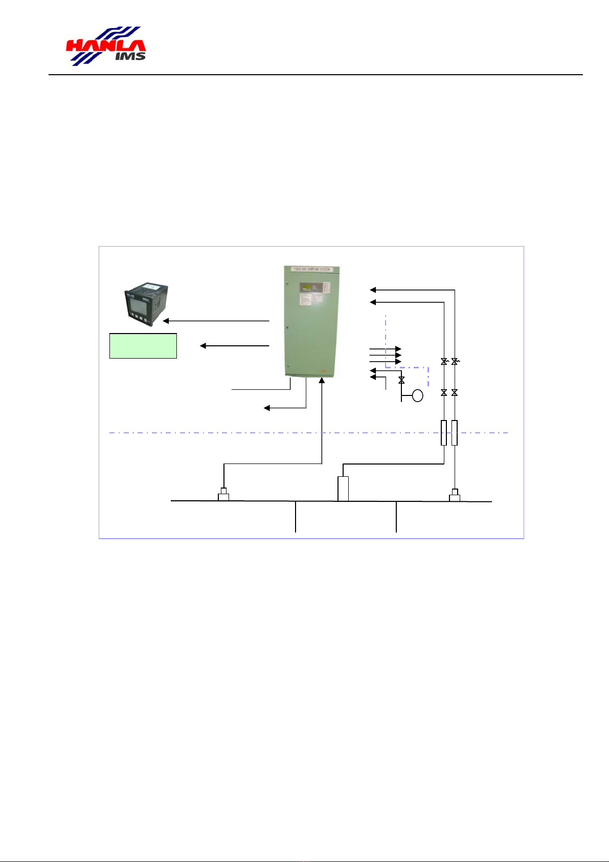
110~240 Vac 50/60Hz
RS-485
RS-485
Main
Remote Repeater
To Monitoring System Exhaust 1
Safety Area
Hazardous Area
Purge Air supply
Calibration gas
Ballast Tank
Top Tank Fitting
Non-Return Valve for wet
suction point
EEx d Flame Arrestor
Shut Off valves
Up to 8 suction channels
Up to 40 suction channels
(Infra-red, Hydrocarbon)
Dry Contact outputs
Void Space
Bulk Head
Penetration
Void Space Fitting
Exhaust 2 Flow Regulating
Needle Valve
Bulk Head
Penetration
(Outdoor)
Pump room Fitting
Pump Room
(Hydrocarbon, Hydrogen Sulphide, Oxygen)
(Gas, System Alarm)
Drain

HANLA IMS CO., LTD.
1610-5 SONGJEONG-DONG GANGSEO-GU BUSAN KOREA
-Tel: 82-51-601-3000
-Fax: 82-51-831-1850
-Email: hanla@hanlaims.co.kr
MT-HGS-100NEW SYSTEM
Rev.9
2010-07-13
Page 7/58
1.3.1 BLOCK DIAGRAM
HGS-100 System has the Analyzing unit, Control unit, Repeater units. Analyzing and Control units are installed in the main
panel.
REPEATER
ALARM UNIT
CONTROL
UNIT
ANALYZING
UNIT MEASURING
PIPES
HAZARDOUS AREA
COMPRESSED AIR
CALIBRATION
WATER
DRAIN
EXHAUST 1,2,3
FLAME ARRESTOR
PIPE SYSTEM
SHUT OFF VALVE
SAFE AREA
MAIN PANEL
The block diagram of the system
HANLA IMS CO., LTD.
1610-5 SONGJEONG-DONG GANGSEO-GU BUSAN KOREA
-Tel: 82-51-601-3000
-Fax: 82-51-831-1850
-Email: hanla@hanlaims.co.kr
MT-HGS-100NEW SYSTEM
Rev.9
2010-07-13
Page 8/58
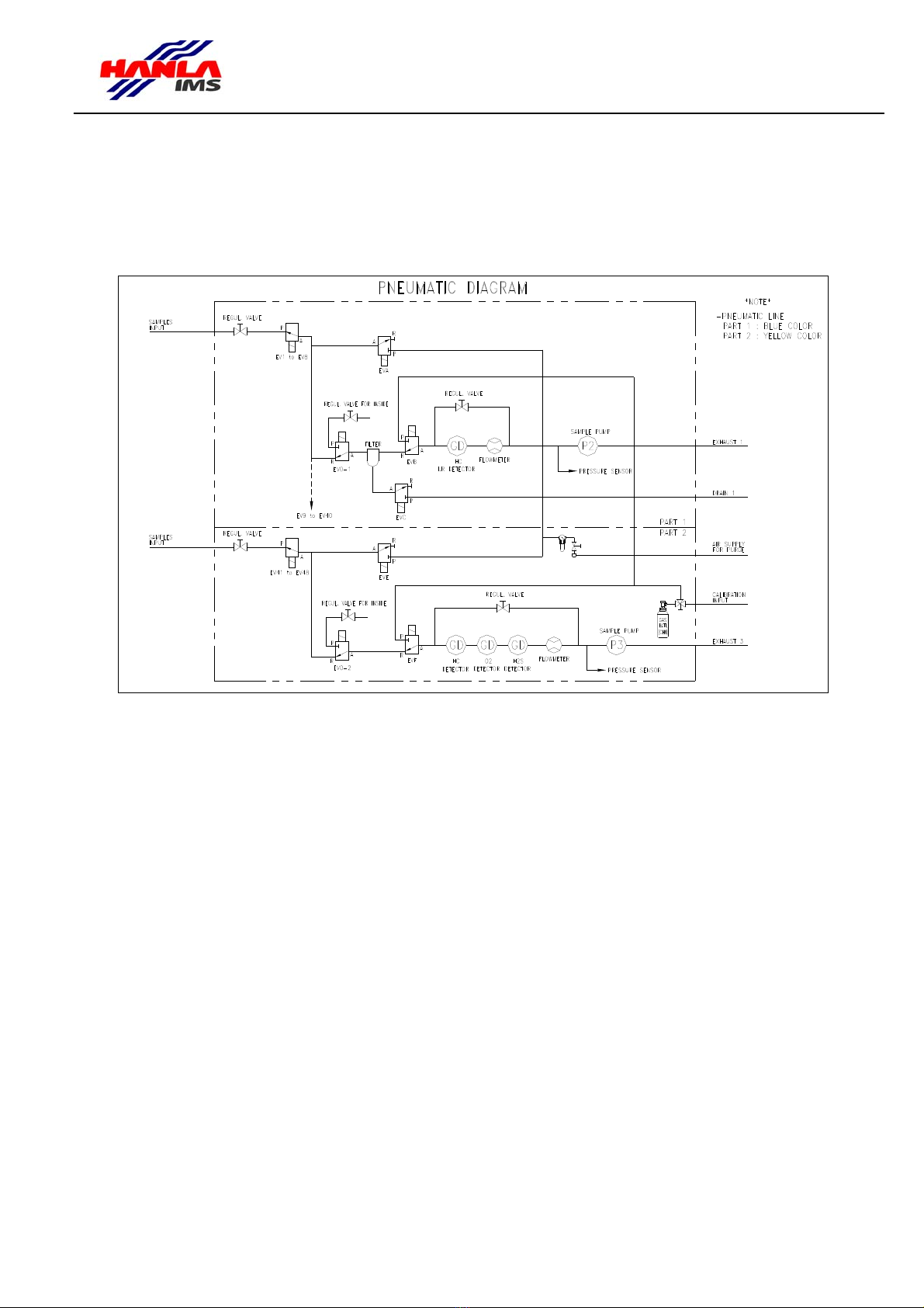
To sample the gas of the BALLAST TANK, the sampling pump(P2) is used. To sample the gas of the PUMP ROOM, the
sampling pump(P3) is prepared. Each channel is controlled by the solenoid valve control. To regulate the gas flow and
check the flowrate, the regulation valve and flowmeter are installed. The moisture from the suction of pipe lines is filtered
by the filter and drained by compulsion
The diagram of the gas flow
Channel Sampling
▪EV1 to EV40 and EV0-1 allow the control of the sampling line for PART1.
▪EV41 to EV48 and EV0-2 allow the control of the sampling line for PART2.
▪P2, P3 are the sampling pumps.
▪EV0-1 allows the cabinet internal atmosphere control, or the P2 pump discharge; In addition, a solenoid valve EV0-1
allows to control the internal atmosphere of the Analyzing Unit, named channel 0.
Channel Purging
▪EVA, EVE allows to proceed to an air purge of selected channel; After suction sampling of a channel, an instrument air
purge is started, in order to correct or prevent ingress of water, moisture, condensation, dust or foreign bodies.
Calibration
▪EVB, EVF allow to drive the Calibration Gas to the detector(s).
▪EVC allows to purge the water trap.
▪Gas Detectors(GD) in Main Sampling Line(Ch.1~40): the Hydrocarbon gas Infrared detector is placed upstream P2
pump(GD on above diagram); other detector(s) is(are) placed downstream P2.
▪Gas Detectors(GD) in PUMP ROOM Sampling Line(Ch.41~48): the Hydrocarbon, O2and H2S gas detectors can be
placed upstream P3 pump(GD on above diagram); other detector(s) is(are) placed downstream P3.

HANLA IMS CO., LTD.
1610-5 SONGJEONG-DONG GANGSEO-GU BUSAN KOREA
-Tel: 82-51-601-3000
-Fax: 82-51-831-1850
-Email: hanla@hanlaims.co.kr
MT-HGS-100NEW SYSTEM
Rev.9
2010-07-13
Page 9/58
1.3. SPECIFICATIONS
1.3.1. ANALYZING UNIT
zSuction channels number : up to 48, copper pipes
zSuction capacity : up to 400 meters I.D. 6mm pipes
zSampling exhaust output : connection to safe area
zCirculation exhaust output : connection to safe area
zDrain Water trap output : connection to safe area
zCalibration Gas input : connection with plastic tube
zInstrument air supply for purge : 4~7bars
z4-20mAAnalog calibrated inputs
for sampling or local detectors : up to 8
z4-20mA inputs accuracy : 0.1%
zOutput power supply for detectors : 24 Vdc
zInternal Detector for Hydrocarbon Gas : Infra-Red type, 4-20mA output
zOther Detectors : miscellaneous type according to gas type
4-20mA 2-wire or 3 wires output, safety class according to their location
zGas concentration alarm levels : 2 adjustable, Pre-Alarm and Alarm
zAlarm fromAnalyzing Unit, : 1 for Gas Alarm
dry contact output 1 for SystemAlarm
1 for Power Supply failure
zCommunication ports : 3 RS485, 1 isolated RS232 or RS485
Default address 1; default baudrate 9600
zOutput power supply for Control Units : 24 Vdc
zOperating/storage temperature for : 0℃to +70℃
Analyzing and Control Units
zLocation for Analyzing and : Safe area in enclosed space (Control
Control Units room, accommodations, bridge,...)
zEnclosure protection : IP22 minimum
zPower Supply : 115/230 Vac 50/60 Hz
zPower consumption : 330 VAwith one Control Unit
340 VA with two Control Units
1.3.2. CONTROL UNIT
zLCD display : 16 lines, 40 columns, back-lighted
zKeypad : tactile type, numeric + functions keys
zindicators : front integrated color LED's
zAlarm : 1 internal buzzer + 1dry contact output
Communication port : RS485
zfront : polyester film
zPower supply : 24 Vdc from Analyzing Unit

HANLA IMS CO., LTD.
1610-5 SONGJEONG-DONG GANGSEO-GU BUSAN KOREA
-Tel: 82-51-601-3000
-Fax: 82-51-831-1850
-Email: hanla@hanlaims.co.kr
MT-HGS-100NEW SYSTEM
Rev.9
2010-07-13
Page 10/58
1.4. Technical Data for Each Component
1.4.1. ANALYZING UNIT
A cabinet named "Analyzing Unit" includes the suction process, sampling gas detector(s) and pneumatic components
for up to 48 channels.
After suction sampling of a channel, an instrument air purge is started, in order to correct or prevent ingress of water,
moisture, condensation, dust or foreign bodies. The picture of analyzing board is following:
In case of several sampling gas detectors, the sampled gas passes through each detector one after the other, so that all
gas concentrations are measured at the same time. An additional Gas detector can easily be installed further. Each Gas
detector can be enabled or disabled at will.
1.4.2. A/D Conversion and Alarm
An electronic module supervises over the suction process, provides up to 8 analog inputs for gas detectors and flow
sensor placed either in BALLAST TANK suction process sampling(2 channels) or in PUMP ROOM suction process
sampling(4 channels). The local gas detectors are classed as additional individual channels as well as additional gas
detectors by using remained 2 channels of AD converter. The analog signal processing by the differential amplification
allows the high impedance and rejection of common-mode noise. To convert the current 4~20 mA to the voltage, the
load resistor 200[Ω] is used
That module periodically performs and saves all gas measurements. It provides a non-volatile memory for saving all
data, alarm status and operating parameters.
The Analyzing Unit provides two high or low gas concentration alarm levels on each channel and each gas (see7.4.2),
monitoring a permanent "Gas alarm" dry contact output (see 6.2):
zpre-alarm limit, to advise that a gas concentration approaches the alarm unit;
zalarm limit, with activation of another dry contact output dedicated to a horn/rotating lamp, until alarm
acknowledgement..
When some gas are without interest for some channels, the relevant alarm limits can be set at the extremities of the gas
range, in order to avoid gas concentration alarm monitoring for that gas on these channels.
The Analyzing Unit provides self-tests : sample flow, internal gas concentration, internal leakproof, detector's current
output, calibration gas flow, communication between Analyzing and Control Units, power supply. These tests monitor a
"System fault" and "Power supply" dry contact outputs.
1.4.3. Communication
This module also manages 4 digital RS485 communication ports(Generally, one for control unit. One for repeater SIL-
100. Then, only 2 ports are available for user interface. MODBUS RTU) and one RS232(for downloading or MODBUS
RTU) isolated communication port for connection to one or more remote Repeaters as described in synopsis, and/or an
external Monitoring System, using MODBUS RTU protocol. TheAnalyzing Unit operates as slave.

HANLA IMS CO., LTD.
1610-5 SONGJEONG-DONG GANGSEO-GU BUSAN KOREA
-Tel: 82-51-601-3000
-Fax: 82-51-831-1850
-Email: hanla@hanlaims.co.kr
MT-HGS-100NEW SYSTEM
Rev.9
2010-07-13
Page 11/58
1.4.4 Gas detectors
The HGS-100 System uses two locations of Gas detectors : inside the Analyzing Unit, in suction process sampled Gas, and
in local areas to be controlled. Any gas detectors of Infrared, catalytic, electro-chemical or any other type, 4-20mA output,
can be connected to the Analyzing Unit.
For Gas detectors located inside the Analyzing Unit, in suction process sampled Gas: detector dedicated to
Hydrocarbon gases is Infrared type, for best reliability and maintenance-free. For Local Gas detectors: Same detectors can
be used, but installed with connection box.
zTo monitor the BALLAST TANK, infra-red type detector is used based on the principle of infra-red absorption.
The quantity of absorption of infra-red is changed by the type of the gas. Thus, the concentration can be determined by the
quantity of the gas.
zTo monitor the PUMP ROOM, solid-state type Detector was adopted.
These detectors have the built-in microprocessor and output the 4~20mA current to interface the other equipments. Here,
these current signals are converted to digital data by the A/D converter of Analyzing Board. Control Board displays those
data from the analyzing board.
1.4.5. Solenoid valves
The 8 solenoid valves are installed on the manifold. The system uses the 9 sets of manifold for total 48 channels of the
sampling points. The supply voltage and power consumption of valve is DC 24V, 4.4W. The maximum pressure is 145 psi
and 2 way type. These solenoid valves are used to connect the air line to the sampling pump sequentially by the control
signal of Control Unit.
1.4.6. flowmeter, regulation valve, filter
Sampled air by the Sampling pump will flow through the air filter to prevent the dust, water, humidity. The filter will drain
the water and dust periodically. The flowmeter shows the flowrate of suction air flows to the detector by the sampling pump.
The regulation valve controls this flowrate.
1.4.7 Analyzing Unit adjacent equipments
zBulkhead penetrations for suction process channels : the number of bulkhead penetration set is defined by the
number of bulkhead to pass through. For each channel a flame-arrestor EEx d class is placed at the limit between
safe and hazardous area, on relevant bulkhead penetration;
zShut-off valves for each channel;
zFlow-regulating valve for each channel allows to equilibrate the flow whatever is the length of the line, for best
efficiency of the system;
zBulkhead penetrations for gas exhaust and filter drain;
zShut-off valve and manometer for instrument air supply for channel purge.

HANLA IMS CO., LTD.
1610-5 SONGJEONG-DONG GANGSEO-GU BUSAN KOREA
-Tel: 82-51-601-3000
-Fax: 82-51-831-1850
-Email: hanla@hanlaims.co.kr
MT-HGS-100NEW SYSTEM
Rev.9
2010-07-13
Page 12/58
1.4.8. CONTROL UNIT
A panel named "Control Unit" includes a backlighted LCD screen for measurements and alarm display, LED
indicators, buzzer/dry contact output for alarm and keyboard for System operation and configuration. The
large LCD screen increases the data availability and the man-machine interface is simplified for easy access
to functions and configuration using scrolling menus. It communicates with the Analyzing Unit using a
Modbus protocol serial link RS485, operating as master in order to get all data and status from the
Analyzing Unit, and to set any configuration change. The Control Unit is powered by 24 Vdc from the
Analyzing Unit.
One Control Unit can be incorporated in the Analyzing Unit or located in a remote box or in existing
console. One or two others can be used as repeater(s), but HGS-100 also can have identical remote
repeaters SIL-100 series by order. As the common database (gas measurements, fault status, operating
parameters) is saved in the Analyzing Unit, all Control Units display the same data. Remote repeaters SIL-
100 series display the summarized information.
Control Unit front overview :
C
F
1
F
5
F
2
F
4
F
3
F
6
HGS-100
9
6
3
8
7
0DIM
2
54
1
IMPORTANT NOTE : the Analyzing Unit and Control Unit operate independently. So, in case of
failure of communication with the Control Unit, the Gas Concentration alarms and System faults
remain under control by way of the Analyzing Unit Gas Alarm and System fault relays.
Table of contents
Popular Measuring Instrument manuals by other brands

Trilithic
Trilithic 720 DSP Operation manual

NuTech
NuTech 3000 manual

Laser Technology
Laser Technology esri TruPoint 300 Quick reference guide

PRECISION DIGITAL
PRECISION DIGITAL ProtEx PD6820 instruction manual

Endress+Hauser
Endress+Hauser Levelflex FMP53 technical information

HBK
HBK MP60 operating manual


