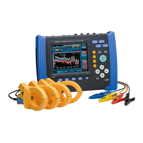
Hioki 3196 User manual

EN50160 MODE
INSTRUCTION MANUAL
3196
POWER QUALITY ANALYZER


Contents i
10
11
Contents
Introduction .................................................................. 1
Symbols ....................................................................... 1
Safety ........................................................................... 1
Outlook of Operating Procedures ................................2
1Overview 3
1.1 Product Overview ............................................... 3
2 Preparation for Measurement 5
2.1 EN50160 Mode and Normal Mode ..................... 5
2.2 EN50160 Screen ................................................ 6
2.3 PC Card .............................................................. 7
2.4 Limitations in EN50160 mode ............................ 8
2.5 Default Values .................................................... 9
3 Measurement 11
3.1 Setting Default Values ......................................11
3.2 Starting Measurement ......................................12
3.3 The EN50160 Screen during Measurement ..... 12
3.3.1 Common Display Areas .....................................13
3.3.2 Overview Screen ...............................................16
3.3.3 Harmonic Screen ...............................................19
3.3.4 Signaling Screen ...............................................22
3.3.5 Events Screen ...................................................24
Contents
ii
4 Detailed Settings 27
4.1 Selecting EN50160 mode .................................27
4.2 Settings for the Measurement System ............. 29
4.3 Threshold Setting .............................................35
4.4 Settings in 3196 Mode Screen .........................41
4.5 PC Card ............................................................42
5 Specifications 43
5.1 Basic Specifications .........................................43
5.2 In EN50160 mode, items that differ from normal
3196 specifications ...........................................44
5.3 EN50160 Measurement Parameters ................ 46
5.4 EN50160 Display Specifications ......................47
5.5 EN50160 Setting Specifications .......................50
5.6 Data Storage ....................................................52
5.7 EN50160 Measurement Specifications ............53
5.8 Calculation Formulas ........................................58

Introduction
1
2
3
4
5
6
7
8
9
10
11
12
13
1
Introduction
3196 EN50160 mode is available on Ver1.30 or later. Note that
EN50160 mode is not available in versions prior to Ver1.30.
Symbols
The following symbols in this manual indicate the relative impor-
tance of cautions and warnings.
Safety
Read the Instruction Manual supplied with the 3196 unit very care-
fully, and follow the indications given under "DANGER," "WARN-
ING," "CAUTION," and "NOTE."
For operating environment, maintenance, and disposal at end of
life, the same conditions apply as to the main 3196.
Refer to the 3196 Instruction Manual for details regarding basic
operation procedures.
Indicatesthat incorrect operation presents a possibility of
injury to the user or damage to the product.
Advisory items related to performance or correct opera-
tion of the product.
❖Indicates the reference.

Outlook of Operating Procedures
2
Outlook of Operating Procedures
Indicates operation keys.
Indicates the screen name
selected with the DF key.
Indicatesthenameofanitem
displayed on the screen.
Displays the item selected in the drop-down
list box accompanied by an explanation.
Indicatesthepurpose
of the settings.

2
3
4
5
6
7
8
9
10
11
12
13
3
The EN50160 version of the 3196 can measure and analyze the power
supply voltage characteristics in accordance with the definitions stated in
the European standard EN50160:1999 “Voltage characteristics of elec-
tricity supplied by public distribution systems”.
Overview 1
1.1 Product Overview
EN50160 Overview Screen

4

1
3
4
5
6
7
8
9
10
11
12
13
5
Model 3196 (Ver1.30 or later) can be used to measure in EN50160
mode in addition to the normal measurement of Model 3196 (nor-
mal mode).
When EN50160 mode is selected, the measurement function for
EN50160 is added to the normal mode, and some functions in nor-
mal mode will be limited.
Refer to Section 2.4, "Limitations in EN50160 mode" (page 8) for
details of the limitations.
Be sure to check that you are in the correct measurement mode
before using the 3196.
Preparation for Measurement 2
2.1 EN50160 Mode and Normal Mode
Changing the mode
MEASURE
EN50160
OFF Normal mode
ON EN50160 mode
Confirm Cancel
Select from pull-
down menu

6
In EN50160 mode, the screen for EN50160 is accessible from the
"EVENT" screen.
In general, there are 3 screen types, and measurement in
EN50160 mode is possible only in these screens.
In addition, screens for normal mode (e.g., Timeplot and DMM) can
be displayed during EN50160 measurement.
2.2 EN50160 Screen

1
3
4
5
6
7
8
9
10
11
12
13
7
When EN50160 mode is selected, the detailed data for EN50160 is
saved into the PC card in real time, and only data for the display is
saved in the internal memory.
Using a PC card is recommended for further analysis after mea-
surement by using the PC application software.
❖Section 4.5, "PC Card" (page 42)
2.3 PC Card

8
The limitations are indicated below.
note *1: Harm Calc For EN
Harmonic Calculation of Voltage is % of Un (Nominal voltage).
Harmonic Calculation of Current and Power are % of Fundamental.
2.4 Limitations in EN50160 mode
Items Fixed value
Wiring (123ch) 3P3W3M or 3P4W
Frequency 50Hz
U Calc Type PHASE-N (3P4W),
LINE-LINE (3P3W3M)
Harm Calc For EN *1
THD Calc THD_F
Flicker Pst, Plt
Filter 230V lamp
MemoryFull LOOP
Interval 10 min
Auto Save BINARY
Events Fixed value
U Transient 123ch ON, 4ch OFF
Urms SWELL ON
Urms DIP ON
U Interrupt ON
Frequency ON (common to Freq.A of EN50160
settings)
U THD (123ch) 123ch ON, 4ch OFF
U unb ON
U Harmonics 123ch ON, 4ch OFF

1
3
4
5
6
7
8
9
10
11
12
13
9
When pressing the default key (F1 key) in the EN50160 setting
screen [EVENT]-[DF4_Setting], the settings related to EN50160
mode is reset to the following default values that are set forth by
the EN50160 standard. The settings for other parameters are not
reset.
2.5 Default Values
Default Values
Items Default Good% Default
Wiring 3P4W -----
U Range 300V -----
PT Ratio 1 -----
U Reference 230V -----
Freq. A (±) ±1.0% 99.5%
Freq. B + +4.0% 100.0%
Freq. B −-6.0%
V Variation A (±) ±10.0% 95.0%
V Variation B + +10.0% 100.0%
V Variation B - -15.0%
Flicker 1.0 95.0%
Unbalance 2.0% 95.0%
THD 8.0% 95.0%
Harmonics(h2-h50) refer to next table 95.0%
Signaling p1 Hz 500Hz
99.0%
Signaling p1 % 9.0%
Signaling p2 Hz 1000Hz
Signaling p2 % 5.0%
Signaling spec1 off (110Hz)
Signaling spec2 off (110Hz)
Transient 180.0% -----
Over voltage(swell) 110.0% -----
Dips 90.0% -----
Interruption 1.0% -----
Short int time 180s -----

10
Signaling
Signaling p1:
Threshold level and the End of frequency in the First area
Signaling p2:
Threshold level and the Start of frequency in the Third area
The threshold level of the first area and the third area is the same
value from the starting frequency to the ending frequency, and the
second area is their transition area.
The threshold level of the second area is decided automatically by
the first and the third areas.
Default value of each Harmonic order
Order % of Un Order % of Un Order % of Un
--- --- 11 3.5 21 0.5
2 2.0120.5220.5
3 5.0133.0231.5
4 1.0140.5240.5
5 6.0 15 0.5 25-50 OFF
60.5160.5
75.0172.0
80.5180.5
91.5191.5
10 0.5 20 0.5
0.3
3
Voltage level (% of Un)
Frequency [kHz]
0.5 1 30.1
1
5
9
10
Signaling p2
(1kHz, 5%)
Signaling p1
(500Hz, 9%)
The first area The second area
The third area

1
3
4
5
6
7
8
9
10
11
12
13
11
To simplify the settings, Model 3196 is programmed with the set-
tings as described in the EN50160 standard as default.
By initializing the settings before starting measurement, EN50160
measurement can be started without making further complicated
settings.
In addition, changing each setting is possible. Please refer to 4.
Detailed settings for details.
Measurement 3
3.1 Setting Default Values
Setting default values
Settings1
Default

12
Start measurement by pressing the START key after wiring and
settings have been completed.
(Example)
When the start key is pressed at 10:05, the 3196 waits to start
measurement until 10:10.
The EN50160 screen is changeable after as well as during mea-
surement. Also, the analysis start date and period to display can
be switched arbitrarily.
The data is displayed on the main unit in one-day units except for
the measurement start date and the last date (including the current
date).
Select either "Excl. Flag" or "Incl. Flag" in each screen to choose
whether or not to analyze the parameters when a dip, swell or
interruption event occurs.
3.2 Starting Measurement
Punctual time measurement start
EN50160 mode starts measurement at the punctual times as
shown below immediately after the START key is pressed.
xx:00:00, xx:10:00, xx:20:00, xx:30:00, xx:40:00, xx:50:00
Until the above times are reached, the 3196 is in waiting status.
10:05 10:10
Waiting
Start key is pressed Measurement starts
3.3 The EN50160 Screen during
Measurement

1
3
4
5
6
7
8
9
10
11
12
13
13
3.3.1 Common Display Areas
*1 Start Indicates measurement start date and time.
*2 End Indicates date and time during measurement or measurement end
date and time.
*3 Duration Indicates duration from start time to end time (now)
*4 Flagging This is offered to see the judgment without the effect of dip, swell
and interruption events which affect all parameters.
When the F4 button is pushed, the indication in the upper right
switches between "Including flagged data" and "Excluding flagged
data".
The display will also change.
Including flagged data: Include flagged data in the statistics
Excluding flagged data: Do not include flagged data in the statistics
*5 Display methods There are three display methods.
All Display the data from measurement start to the
present (or end) time
Previous Display the data for a designated period recorded
prior to the present (or end) time
Specific Display the data for a designated period from a speci-
fied date
*6 Start date of
display When "Specific" is chosen as the display method, the date can be
input.
When "Previous" is chosen as the display method, "Before:Now" or
"Before:End" is displayed.
*7 Period of
display When "Previous" or "Specific" is chosen as the display method, the
period can be selected.
Note that only periods shorter than the recorded period can be
selected.
(e.g.)Recorded period:10 days, choose from 1 day or 1 week only.
*8 An actual dis-
play period Indicate an actual display date from the display start date to the dis-
play end date.
The time is not displayed, but it means from 00:00 of the start date
to 23:59 of the end date.
When the background turns orange, this indicates that data on the
display start date or the display end date did not reach a day.
Measurement start time*1
Present time or end time *2 Flagging (Including
flagged data or Exclud-
ing flagged data) *4
Display methods
(All/ Previous/
Specific) *5 Start date of display
(Only when Specific
is chosen) *6 Period of display *7
An actual display period *8
Duration from start time
to end time (now) *3

14
Sample combinations of the display method and period
Method Start date Period
ex.1 All --- ---
ex.2 Previous --- 1 day
ex.3 Previous --- 1 week
ex.4 Specific 01/02 (Jan./2nd) 1 day
ex.5 Specific 01/02 (Jan./2nd) 1 week
ex.6 Specific 01/02 (Jan./2nd) 2 weeks
1st 2nd 3rd ...
1/1
8:00
Measurement start
8th 9th ... 14th 15th
ex.1
ex.2
ex.3
ex.4 ex.5 ex.6
1/15
16:00
Measurement end
Duration : 14d 8:00
Indicates data does not reach a day.
Background turns red for the item of an actual display
period.
Note:
The latest data is always displayed when "Previous" is chosen
during the measurement.

1
3
4
5
6
7
8
9
10
11
12
13
15
The ratio of Good judgment in the designated period is displayed
as a numeric value and bar graph.
The left end of the bar graph indicates 0% and the right end indi-
cates 100%.
Also, the results of the comparison ratio and the Good% is
expressed by the color.
When there are no recorded data, it is displayed as the following
figure.
e.g.) Right after measurement start.
or When Excl. Flag is chosen under the conditions which flagging
occurs in frequently.
Red: the ratio of Good judgment is
less than Good%.
Blue: the ratio is more than or equal
to Good%.

16
3.3.2 Overview Screen
Display all the measurement parameters for EN50160 measure-
ment.
The details of each screen are explained as follows.
Overview
Thenumber oftimes
for each event
Parameter name
Good%
Threshold level
Bar graph and
numeric values
Freq.A
Freq.B
Vvari.A
Vvari.B
The following 4 parameters are simplified and displayed.
Other manuals for 3196
3
Table of contents
Other Hioki Measuring Instrument manuals

Hioki
Hioki 3506-10 Parts list manual

Hioki
Hioki PW3198 User manual

Hioki
Hioki PW3365-20 User manual

Hioki
Hioki 3280-10F User manual

Hioki
Hioki VT1005 User manual

Hioki
Hioki IM3536-01 User manual

Hioki
Hioki TM6102 Use and care manual

Hioki
Hioki SM7420 User manual

Hioki
Hioki 3447-01 User manual

Hioki
Hioki MR8847A User manual