vi
K114 Issue No. 9
Table of Contents (contd)
Section page
MINIMUM SET-UP ............................................................................................................................................................ 6-26
SETUP, [UNITS], [AERO] ........................................................................................................... 6-26
SETUP, [UNITS], [PRESS] .......................................................................................................... 6-26
SETUP, [LIMITS] ........................................................................................................................... 6-26
SETUP, ALT/Ps.............................................................................................................................. 6-27
SETUP, PORT ................................................................................................................................. 6-27
SETUP, HELP ................................................................................................................................. 6-27
6.4 CONFIGURATION ....................................................................................................................................... 6-28
Procedure...................................................................................................................................... 6-28
Functions ....................................................................................................................................... 6-28
CONFIG,[UNITS] .......................................................................................................................... 6-29
CONFIG, [LIMITS],[EDIT LIMITS],[EDIT EXISTING] .......................................................... 6-29
NAME ............................................................................................................................................... 6-30
MIN ALT,MAX ALT, MIN CAS, MAX CAS ............................................................................. 6-30
MAX MACH .................................................................................................................................... 6-30
MAX ROC, MAX RATE CAS ....................................................................................................... 6-30
MIN Ps, MAX Ps, MIN Qc, MAX Qc ....................................................................................... 6-30
MAX RATE Ps, MAX RATE Qc.................................................................................................. 6-30
ARINC LIMITS ............................................................................................................................... 6-30
ALTITUDE CORRECTION .......................................................................................................... 6-31
SAVING LIMITS ............................................................................................................................. 6-31
CONFIG, [LIMITS],[EDIT LIMITS],[MAX LIMITS] ................................................................ 6-32
CONFIG, [LIMITS],[EDIT LIMITS],[EDIT NEW] ................................................................... 6-32
CONFIG, [LIMITS],[CLEAR LIMITS] ........................................................................................ 6-32
CONFIG, [LIMITS],[LOCK AIRCRAFT] ................................................................................... 6-32
CONFIG, [LIMITS],[DEFAULT AIRCRAFT] ........................................................................... 6-32
CONFIG, [MORE],[CONTROL],[CONTROL MODE] .......................................................... 6-32
CONFIG, [MORE],[CONTROL],[CONTROL LOCK] ........................................................... 6-32
CONFIG, [MORE],[DISPLAY/OPTIONS],[DISPLAY TYPE] .............................................. 6-32
CONFIG, [MORE],[DISPLAY/OPTIONS],[OPTIONS] ........................................................ 6-32
CONFIG, [MORE],[DATE/FORMAT] ....................................................................................... 6-32
CONFIG, [MORE],[SETUP MODE] .......................................................................................... 6-33
FULL ................................................................................................................................................. 6-33
MINIMUM ....................................................................................................................................... 6-33
OFF ................................................................................................................................................... 6-33
CONFIG, SPEED,[AUTO ZERO] ............................................................................................... 6-33
CONFIG, SPEED,[CAS/TAS] ..................................................................................................... 6-33
CONFIG, SPEED,[Pt TEMPERATURE] ................................................................................... 6-33
CONFIG, RATE TIMER ................................................................................................................ 6-33
CONFIG, RATE .............................................................................................................................. 6-33
CONFIG, LEAK MEASURE, [AUTO LEAK ON/OFF] ......................................................... 6-33
CONFIG, LEAK MEASURE, [AUTO LEAK LOCK] .............................................................................. 6-33
CONFIG, LEAK MEASURE, [AUTO LIMIT ON/OFF] ......................................................................... 6-33
CONFIG, LEAK MEASURE, [AUTO LIMIT LOCK] .............................................................................. 6-33
CONFIG, GROUND ..................................................................................................................................... 6-33
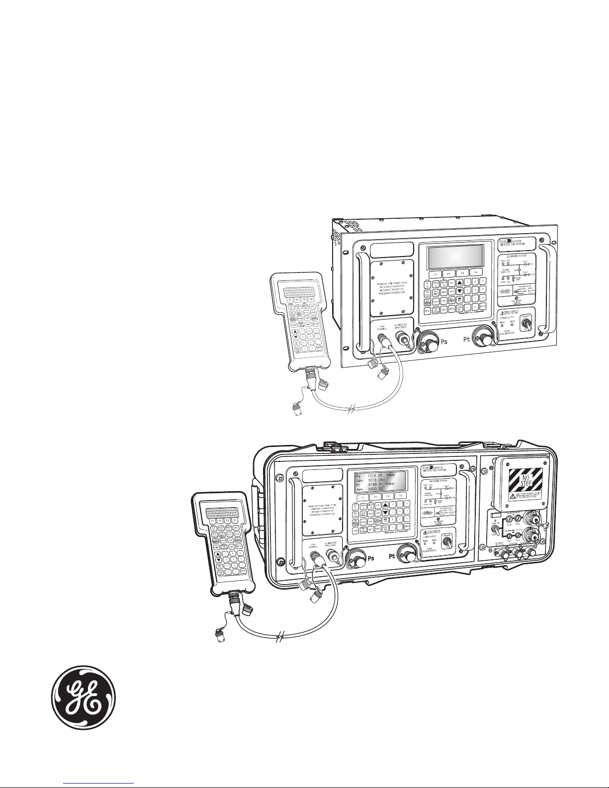
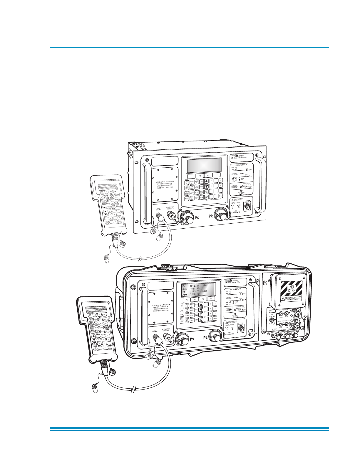
Druck ADTS 405 User Manual