THERMACUT EX-TRAFIRE 45SD User manual

THERMACUT®
EX-TRAFIRE®
45SD
PLASMA ARC CUTTING SYSTEM
Operator Manual
EX-2-902-003
N-22226
Revision: T-5
English
2020
BEFORE SWITCHING ON OR OPERATING THE SYSTEM,
READ THIS MANUAL, BECOME FAMILIAR WITH THE
CONTENT. KEEP THE MANUAL LOCAL TO THE JOB SITE
WITH EASY ACCESS TO ALL PERSONNEL. THE SYSTEM IS TO BE USED FOR METAL
CUTTING ONLY.
PLEASE, CHECK THE LATEST VERSION OF THE OPERATOR MANUAL ON OUR WEBSITE:
www.ex-trafire.com
!IMPORTANT!

EX-TRAFIRE®45SD
Operator Manual, Revision T-52
SECTION 1: SAFETY ��������������������������������������������������������������������������������������5
!Caution! ��������������������������������������������������������������������������������������������������������������������������������������6
Plasma arc rays can burn eyes and skin�����������������������������������������������������������������������������������6
Noise can damage hearing ������������������������������������������������������������������������������������������������������6
Flying sparks (arc spray) can cause injury, fire or explosion��������������������������������������������������6
Caution! Readoperator’smanual���������������������������������������������������������������������������������������������6
Cutting can cause fire or explosion �����������������������������������������������������������������������������������������7
Electric shock can kill������������������������������������������������������������������������������������������������������������������7
Plasma arc can injure������������������������������������������������������������������������������������������������������������������7
Flying sparks (arc spray) can cause injury, fire or explosion��������������������������������������������������7
Hot parts can cause severe burns���������������������������������������������������������������������������������������������7
Smoke and gases can be hazardous����������������������������������������������������������������������������������������8
Caution when cutting around gas cylinders����������������������������������������������������������������������������8
Do not exceed the recommended duty cycle, this can lead to overheating and cause
damage to the system����������������������������������������������������������������������������������������������������������������8
Magnetic field can affect pacemakers �������������������������������������������������������������������������������������8
Plasma cutting can cause interference�������������������������������������������������������������������������������������8
Safety Sticker �������������������������������������������������������������������������������������������������������������������������������9
SECTION 2: SPECIFICATIONS ����������������������������������������������������������������� 2-10
Dimensions and weight of the plasma arc power supply �����������������������������������������������2-11
Specifications: plasma arc power supply EX-TRAFIRE®45SD, 1- phase �������������������������2-12
Specifications: plasma arc power supply EX-TRAFIRE®45SD, 3- phase �������������������������2-13
Specifications: Torches FHT-EX®45TTH and FHT-EX®45TTM�������������������������������������������2-14
Dimensions and configuration��������������������������������������������������������������������������������������������2-15
Hand torch FHT-EX®45TTH ��������������������������������������������������������������������������������������������������2-15
Machine torch FHT-EX®45TTM ��������������������������������������������������������������������������������������������2-15
Symbols and marking�����������������������������������������������������������������������������������������������������������2-16
SECTION 3: INSTALLATION��������������������������������������������������������������������� 3-18
Upon receipt of goods���������������������������������������������������������������������������������������������������������3-19
Claims�������������������������������������������������������������������������������������������������������������������������������������3-19
Box contents��������������������������������������������������������������������������������������������������������������������������3-19
Power supply location ����������������������������������������������������������������������������������������������������������3-20
Mains power connection �����������������������������������������������������������������������������������������������������3-20
Connecting to an engine drive power generator�������������������������������������������������������������3-20
Grounding �����������������������������������������������������������������������������������������������������������������������������3-21
Mains power lead �����������������������������������������������������������������������������������������������������������������3-21
Single-phase mains power lead������������������������������������������������������������������������������������������3-21
Installation of single-phase mains power lead������������������������������������������������������������������3-22
INDEX

EX-TRAFIRE®45SD
Operator Manual, Revision T-5 3
Three-phase mains power lead ������������������������������������������������������������������������������������������3-22
Installation of three-phase mains power lead�������������������������������������������������������������������3-22
Torch installation step by step���������������������������������������������������������������������������������������������3-23
Working (ground) cable installation step by step�������������������������������������������������������������3-26
Plasma gas supply ����������������������������������������������������������������������������������������������������������������3-27
Additional gas filtration��������������������������������������������������������������������������������������������������������3-27
Gas supply installation ���������������������������������������������������������������������������������������������������������3-28
Gas supply regulation ����������������������������������������������������������������������������������������������������������3-28
System CNC interface connection��������������������������������������������������������������������������������������3-29
Activating an external DC coil with an external power supply ���������������������������������������3-30
Activating an external AC coil with an external power supply����������������������������������������3-30
Activating an industrial isolated module with an external power supply����������������������3-31
The circle cutting guide installation - for the FHT-EX®105RTXH/105TTH/45TTH���������3-32
SECTION 4: OPERATION ������������������������������������������������������������������������� 4-35
Front view�������������������������������������������������������������������������������������������������������������������������������4-36
LCD display details ���������������������������������������������������������������������������������������������������������������4-36
Setting of power supply�������������������������������������������������������������������������������������������������������4-37
1� Mode selection� ����������������������������������������������������������������������������������������������������������������4-37
2� Cutting parameters�����������������������������������������������������������������������������������������������������������4-38
3� Two variants of cutting torch� ������������������������������������������������������������������������������������������4-38
Rear view, Turn ON ���������������������������������������������������������������������������������������������������������������4-39
Rear panel detail�������������������������������������������������������������������������������������������������������������������4-39
Cutting preparation��������������������������������������������������������������������������������������������������������������4-40
Manual cutting operation ����������������������������������������������������������������������������������������������������4-40
Hand torch consumables installation���������������������������������������������������������������������������������4-41
Operating the hand torch����������������������������������������������������������������������������������������������������4-42
Operating the torch safety trigger��������������������������������������������������������������������������������������4-42
Fit the work clamp ����������������������������������������������������������������������������������������������������������������4-43
Edge start cutting������������������������������������������������������������������������������������������������������������������4-43
Hand torch cutting technique ���������������������������������������������������������������������������������������������4-44
Piercing ����������������������������������������������������������������������������������������������������������������������������������4-45
Gouging���������������������������������������������������������������������������������������������������������������������������������4-46
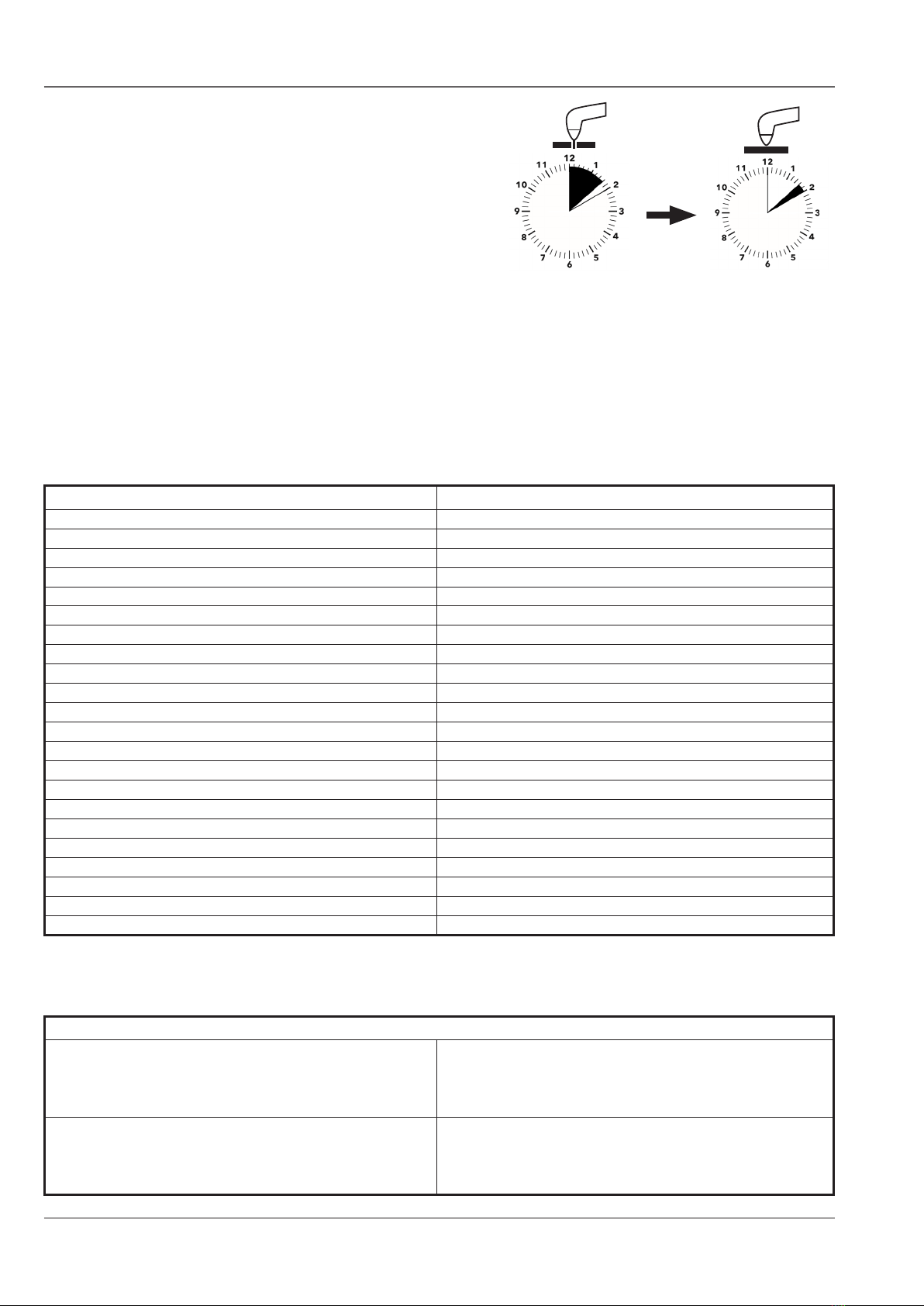
Alignment of the machine torch FHT-EX®45TTM��������������������������������������������������������������4-46
Machine torch consumables installation ���������������������������������������������������������������������������4-47
Mechanized Cutting Charts,30 A Cutting, Shielded Configuration ����������������������4-48
Mechanized Cutting Charts,30 A Cutting, Shielded Configuration ����������������������4-49
Mechanized Cutting Charts,45 A Cutting, Shielded Configuration ����������������������4-50
Mechanized Cutting Charts,45 A Cutting, Shielded Configuration ����������������������4-51
SECTION 5: MAINTENANCE�������������������������������������������������������������������� 5-52
Routine maintenance �����������������������������������������������������������������������������������������������������������5-53
Consumable parts inspection ���������������������������������������������������������������������������������������������5-54

EX-TRAFIRE®45SD
Operator Manual, Revision T-54
Purging/draining the built-in filter��������������������������������������������������������������������������������������5-55
SECTION 6: TORCHES AND TORCH PARTS��������������������������������������������� 6-56
FHT-EX®45TTH Hand Torch Assembly��������������������������������������������������������������������������������6-57
FHT-EX®45TTH Hand Torch Components��������������������������������������������������������������������������6-58
FHT-EX®45TTH Hand Torch Consumables�������������������������������������������������������������������������6-59
FHT-EX®45TTM Machine Torch Assembly��������������������������������������������������������������������������6-60
FHT-EX®45TTM Machine Torch Components��������������������������������������������������������������������6-61
FHT-EX®45TTM Machine Torch Consumables�������������������������������������������������������������������6-62
SECTION 7: ADITIONAL ORDERING INFORMATION ������������������������������ 7-63
SECTION 8: TROUBLESHOOTING ����������������������������������������������������������� 8-64
SECTION 9: ACCESSORIES���������������������������������������������������������������������� 9-69
Filter-EX Compressed Air Filter with replacement filter cartridge����������������������������������9-69
Filter-EX Quick Connect Couplings������������������������������������������������������������������������������������9-70
CNC interface������������������������������������������������������������������������������������������������������������������������9-70
O-Ring lubricant��������������������������������������������������������������������������������������������������������������������9-70
Circle cutting guide kit for FHT-EX®105RTXH/105TTH/45TTH ���������������������������������������9-71
SECTION 10: SYSTEM CIRCUIT DIAGRAM �������������������������������������������� 10-72
Power supply block diagram���������������������������������������������������������������������������������������������10-72
SECTION 11: DISPOSAL OF PRODUCT ������������������������������������������������� 11-73
Use and disposal of waste�������������������������������������������������������������������������������������������������11-73
End of lifetime product disposal���������������������������������������������������������������������������������������11-73
SECTION 12: WARRANTY ��������������������������������������������������������������������� 12-74
Notes:�����������������������������������������������������������������������������������������������������������������������������������12-75
Notes:�����������������������������������������������������������������������������������������������������������������������������������12-76
Notes:�����������������������������������������������������������������������������������������������������������������������������������12-77
Revision history: ������������������������������������������������������������������������������������������������������������������12-78

EX-TRAFIRE®45SD
Operator Manual, Revision T-5 5
SECTION 1�
SAFETY:
!Caution! ��������������������������������������������������������������������������������������������������������������������������������������6
Plasma arc rays can burn eyes and skin�����������������������������������������������������������������������������������6
Noise can damage hearing ������������������������������������������������������������������������������������������������������6
Flying sparks (arc spray) can cause injury, fire or explosion��������������������������������������������������6
Caution! Read operator’s manual���������������������������������������������������������������������������������������������6
Cutting can cause fire or explosion �����������������������������������������������������������������������������������������7
Electric shock can kill������������������������������������������������������������������������������������������������������������������7
Plasma arc can injure������������������������������������������������������������������������������������������������������������������7
Flying sparks (arc spray) can cause injury, fire or explosion��������������������������������������������������7
Hot parts can cause severe burns���������������������������������������������������������������������������������������������7
Smoke and gases can be hazardous����������������������������������������������������������������������������������������8
Caution when cutting around gas cylinders����������������������������������������������������������������������������8
Do not exceed the recommended duty cycle, this can lead to overheating and cause
damage to the system����������������������������������������������������������������������������������������������������������������8
Magnetic field can affect pacemakers �������������������������������������������������������������������������������������8
Plasma cutting can cause interference�������������������������������������������������������������������������������������8
Safety Sticker �������������������������������������������������������������������������������������������������������������������������������9
SECTION 1: SAFETY
EX-TRAFIRE®45SD
Operator Manual, Revision T-56
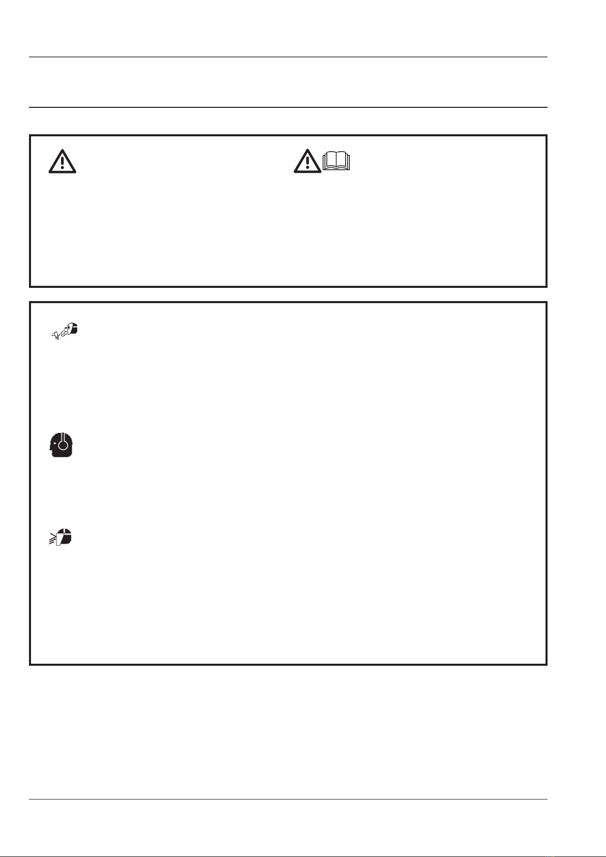
SAFETY
The symbol shown in this section means: !Caution! !Beware!
There are possible hazards with this procedure!
When you find this symbol in the manual or on the system,
be cautious, and follow the related instructions to avoid the
hazard�
Follow the safety instructions to avoid danger�
Only qualified persons should install, operate, maintain and
repair the system�
Keep out of reach of children�
Prolonged exposure to noise from plasma cutting/gouging
can cause hearing damage�
• Use approved ear protection when operating the
plasma system�
• Warn others about the dangers of noise�
NOISE CAN DAMAGE HEARING
!CAUTION!
Flying sparks are created during the metal cutting/gouging
processes; the area around the cutting process should be kept
free from flammables�
• Use face shield/safety glasses with side protection�
• Wear flame resistant clothing, footwear and hand
protection�
• Use earplugs/defenders that are flame resistant to
prevent sparks entering the ear and to reduce the
noise level�
FLYING SPARKS (ARC SPRAY) CAN
CAUSE INJURY, FIRE OR EXPLOSION
1
PLASMA ARC RAYS CAN BURN EYES AND SKIN
• Use face protection (welding helmet or shield) with
the correct shade of filter lens fitted to protect your
eyes and face (see Table 1�1)�
• Warn people of the dangers of looking at the arc,
use signs to warn/inform�
Arc rays from the cutting/gouging processes produce intense
visible and invisible rays that can burn eyes and skin�
Use protective clothing made from durable, flame-resistant
material, appropriate footwear and hand protection�
2
CAUTION!
READOPERATOR’SMANUAL
EX-TRAFIRE®45SD
Operator manual, Revision T-5 7
Touching electrical parts could cause a fatal shock or severe
burns�
• Do not touch live electrical components�
• Wear dry insulated gloves, shoes and protective clothing�
• Insulate yourself from the work and ground using dry
insulating material large enough for the work area�
• The working area should be clean and dry�
• Switch OFF the system for cleaning and maintenance
operations�
• Do not wrap cables around your body�
• Turn OFF the machine when not in use�
ELECTRIC SHOCK CAN KILL
• Periodically check the power supply cable, to insure
that the outer insulation is intact� Replace the power
supply cable immediately if damaged� DO NOT use
the system with bare or exposed wires, this is highly
dangerous�
• Before removing the cover or handling any of the
internal components of the system, wait 5 (FIVE)
minutes to ensure complete discharge of the
capacitors�
• Keep the system in good condition; repair or replace
damaged parts immediately� Maintain the system in
accordance with the manual�
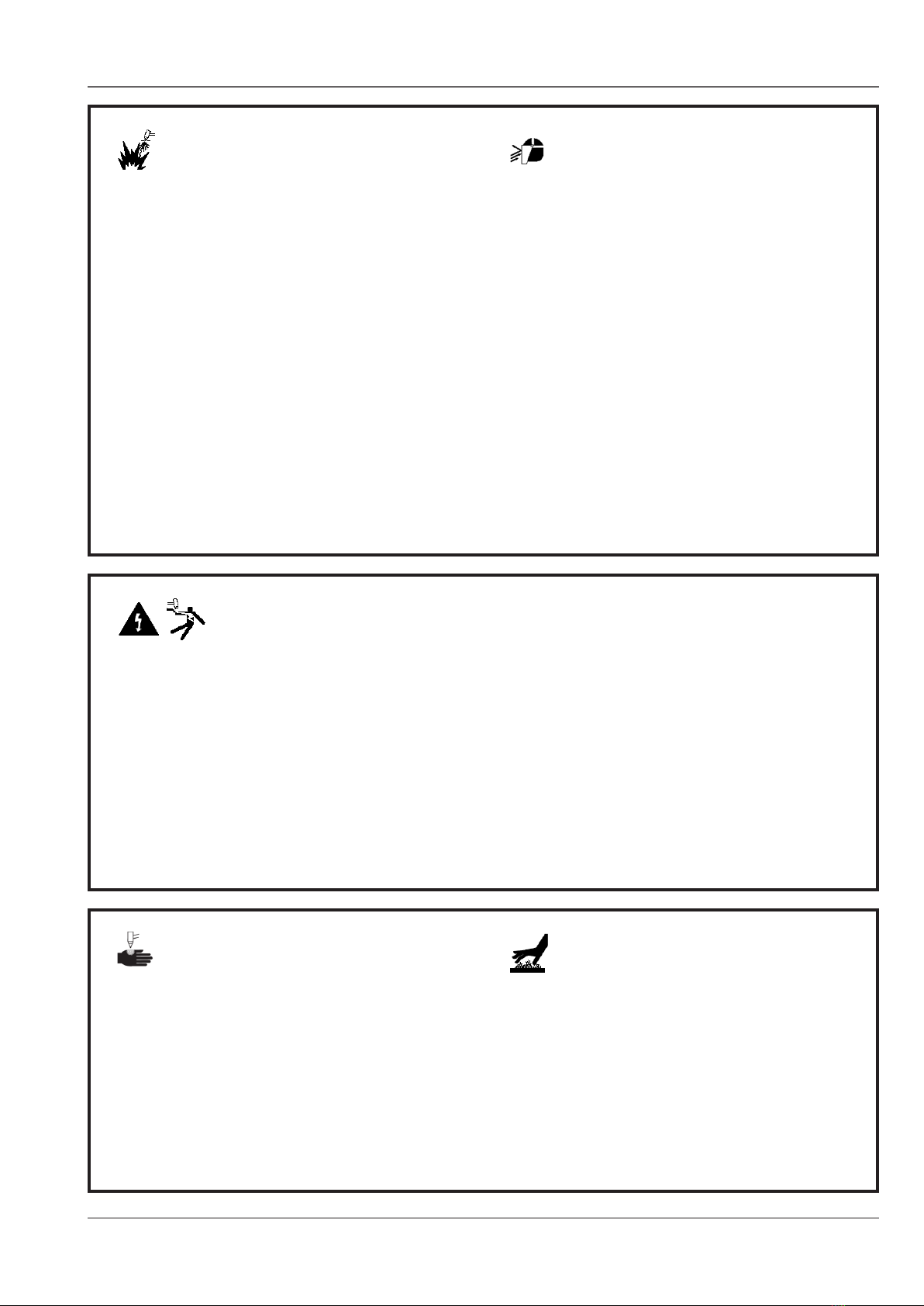
FIRE PREVENTION
• Keep flammable items away from the work area�
• Ensure that there is a fully charged fire extinguisher in the
work area�
• Ventilate the work area, check for flammable/combustible
gases, liquids and materials, remove prior to cutting as
they present a fire risk�
EXPLOSION PREVENTION
• Do not cut in areas containing explosives, flammable
gases or vapors�
• Do not place the system on, over, or near combustible
surfaces�
• Do not operate the system in areas with an atmosphere
containing high concentrations of dust, flammable gases
or vapors�
• Do not use the system to cut pressurized containers that
have not been de-pressurized, vented and cleaned�
Caution! After cutting, the work piece will be HOT!
• Do not touch hot parts bare handed, wear suitable
hand protection�
• Allow cooling time before handling�
CUTTING CAN CAUSE FIRE
OR EXPLOSION
Flying sparks are created during the metal cutting/gouging
processes; the area should be kept free from flammables�
• Use face shield/safety glasses with side protection�
• Wear flame resistant clothing, footwear and hand
protection�
• Use earplugs/defenders that are flame resistant to
prevent sparks entering the ear and to reduce the
noise level�
FLYING SPARKS (ARC SPRAY) CAN
CAUSE INJURY, FIRE OR EXPLOSION
The plasma arc is activated immediately after the torch trigger
is depressed�
• Turn off the power before changing the torch
consumables, the plasma arc can burn through skin and
gloves�
• Do not place your hand or hold the work piece near the
cutting path�
• Do not point the torch toward yourself or other persons�
PLASMA ARC CAN INJURE
3
4
5
HOT PARTS CAN CAUSE SEVERE BURNS
EX-TRAFIRE®45SD
Operator Manual, Revision T-58
Gas cylinders which contain gas under high pressure can
rupture and explode if damaged�
• Handle and use compressed gas cylinders in accordance
with local or national codes�
• Never allow electrical contact between the plasma arc
and a cylinder�
• Never expose cylinders to excessive heat, sparks, slag or
flames�
CAUTION WHEN CUTTING
AROUND GAS CYLINDERS
Plasma Arc Cutting
Current
Protection glass
shade number*
Up to 150 A ISO (DIN) 11
150 A to 250 A ISO (DIN) 12
250 A to 400 A ISO (DIN) 13
OVER 400 A ISO (DIN) 14
* According to ISO 4850:1979
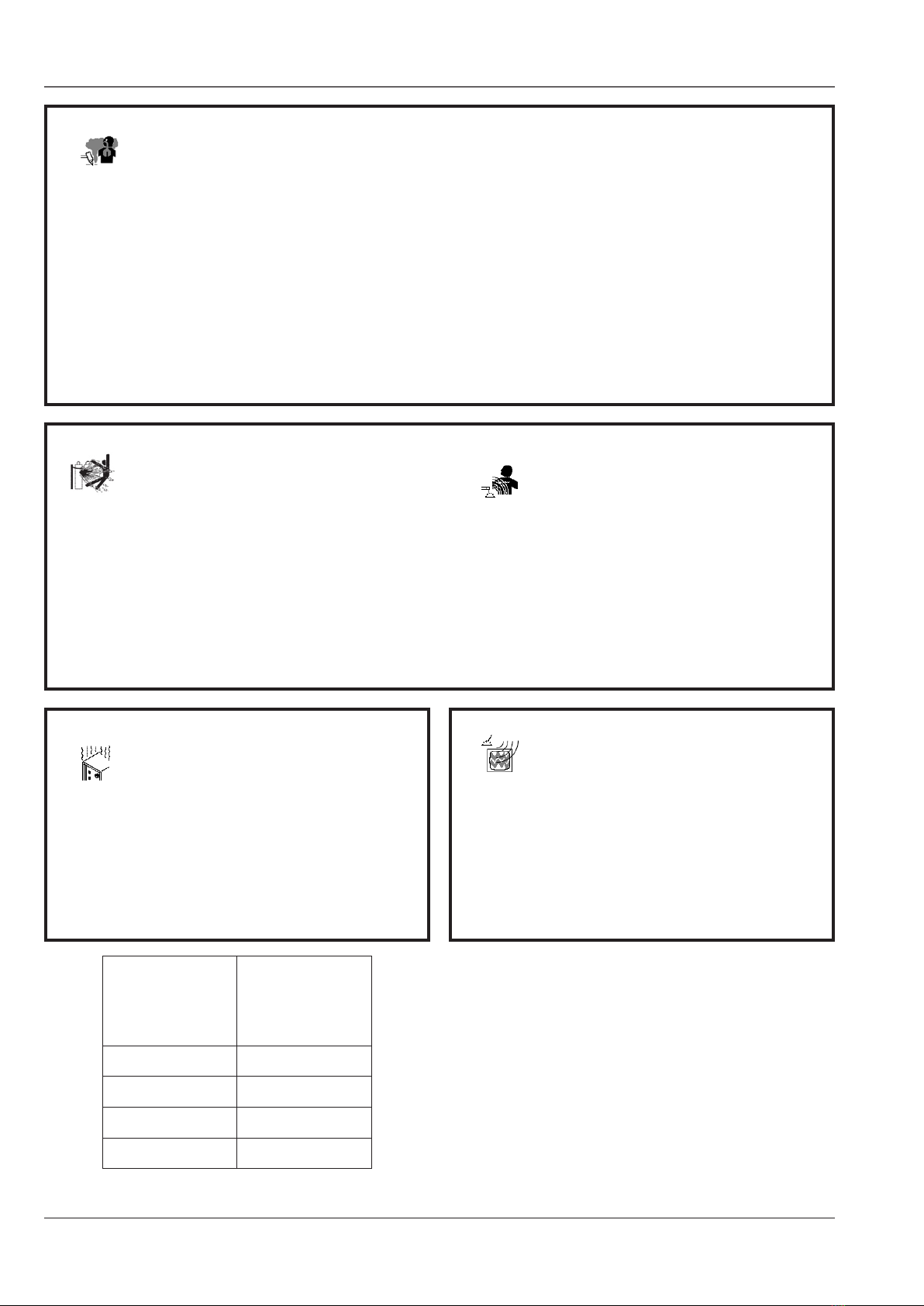
Induction heating of certain materials, adhesives, and fluxes
may cause fumes or smoke�
Breathing the fumes and smoke can be hazardous to your
health�
• Keep your face out of the smoke, do not breathe the
fumes�
• Use local exhaust ventilation for fume removal�
• If ventilation is poor, wear an approved air-supplied
respirator�
SMOKE AND GASES CAN
BE HAZARDOUS
• Work in a confined space only if it is well ventilated,
or while wearing an air-supplied respirator� The
smoke and gases from the cutting/gouging process
can displace air and lower the oxygen level causing
injury or death�
• Monitor the breathable air quality as required�
MAGNETIC FIELD CAN
AFFECT PACEMAKERS
• People with pacemakers/hearing aids should avoid
close contact with plasma arc power supply�
• People with pacemakers/hearing aids should consult
their doctor before operating plasma arc power
supply�
Do not exceed the recommended duty
cycle, this can lead to overheating
and cause damage to the system�
• Allow a suitable cooling off period with high demand
usage�
• Observe the duty cycle rating shown on the label
attached to the system�
PLASMA CUTTING CAN
CAUSE INTERFERENCE
• Electromagnetic energy can interfere with sensitive
electronic equipment such as computers, or
computer-driven equipment�
• Ensure that all equipment in the cutting area is
electromagnetically compatible�
• Ensure that the plasma arc cutting system is installed
and positioned in accordance with this manual�
6
7
EX-TRAFIRE®45SD
Operator manual, Revision T-5 9
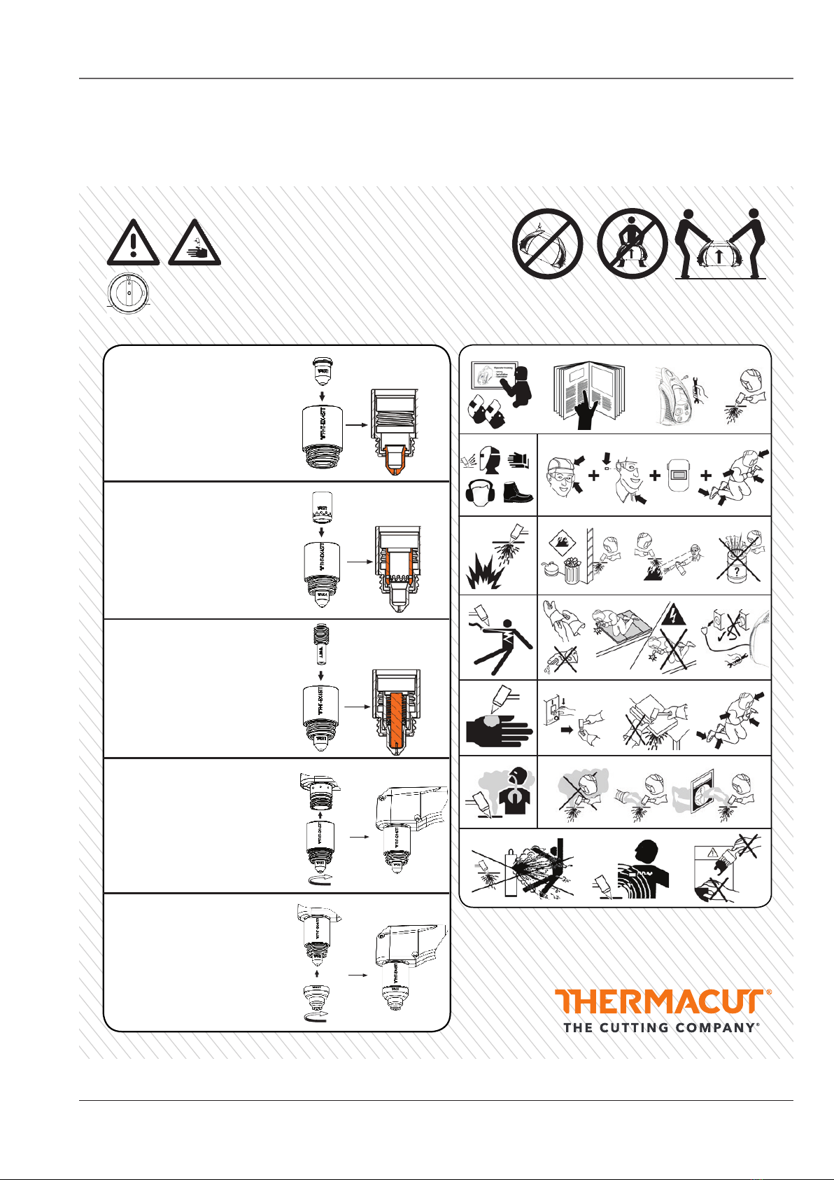
Safety Sticker
WARNING!
Plasma arc is generated immediately
when the torch trigger is depressed.
Plasma arc is generated immediately when the torch trigger is
depressed. The plasma arc will cut quickly through gloves and skin.
Make sure the power is switched off before changing consumables.
+ = +
1
2
3
4
6
2.1
3.1 3.2 3.3
4.1 4.2 4.3
5.1 5.2 5.3
6.1 6.2 6.3
5
7
Torch consumable installation Safety instructions
EX-0-904-014
N-22225
1. Insert the nozzle into the
retaining cap.
2. Insert the swirl ring into the
assembly
(nozzle retaining cap + nozzle).
3. Insert the electrode into the
assembly
(nozzle retaining cap +
nozzle + swirl ring).
5. Screw on the shield
and tighten by hand.
Do NOT overtighten.
EX-TRAFIRE®45HD
Operator Manual, Revision T-1 1
Hand torch consumables installation
WARNING
Plasma arc is generated immediately
when the torch trigger is depressed
Plasma arc is generated immediately when the torch trigger is depressed.
The plasma arc will cut quickly through gloves and skin.
Make sure the power is switched off before changing consumables.
1. Insert the nozzle into the retaining cap. 2. Insert the swirl ring into the assembly
(nozzle retaining cap + nozzle).
3. Insert the electrode into the assembly
(nozzle retaining cap + nozzle + swirl
ring).
4. Screw on this whole assembly (retaining cap + nozzle +
electrode + swirl ring) to the seat bottom of the torch and
tighten by hand. Do NOT overtighten.
The nozzle must seat properly without any movement.
If not, reasseble it and put these parts together again.
5. Screw on the shield and tighten by hand.
Do NOT overtighten.
SHIELD NOZZLE RETAINING CAP NOZZLE SWIRL RING ELECTRODE TORCH
Cross - section
of assembly.
Cross - section
of assembly.
Cross - section
of assembly.
4. Screw on this whole assembly
(retaining cap + nozzle +
electrode + swirl ring)
to the seat bottom of the torch
and tighten by hand. Do NOT
overtighten. The nozzle must seat
properly without any movement.
If not, reasseble it and put these
parts together again.
EX-TRAFIRE®45HD
Operator Manual, Revision T-1 1
Hand torch consumables installation
WARNING
Plasma arc is generated immediately
when the torch trigger is depressed
Plasma arc is generated immediately when the torch trigger is depressed.
The plasma arc will cut quickly through gloves and skin.
Make sure the power is switched off before changing consumables.
1. Insert the nozzle into the retaining cap. 2. Insert the swirl ring into the assembly
(nozzle retaining cap + nozzle).
3. Insert the electrode into the assembly
(nozzle retaining cap + nozzle + swirl
ring).
4. Screw on this whole assembly (retaining cap + nozzle +
electrode + swirl ring) to the seat bottom of the torch and
tighten by hand. Do NOT overtighten.
The nozzle must seat properly without any movement.
If not, reasseble it and put these parts together again.
5. Screw on the shield and tighten by hand.
Do NOT overtighten.
SHIELD NOZZLE RETAINING CAP NOZZLE SWIRL RING ELECTRODE TORCH
Cross - section
of assembly.
Cross - section
of assembly.
Cross - section
of assembly.
Cross - section
of assembly.

EX-TRAFIRE®45SD
Operator Manual, Revision T-52-10
Dimensions and weight of the plasma arc power supply �����������������������������������������������2-11
Specifications: plasma arc power supply EX-TRAFIRE®45SD, 1-phase ��������������������������2-12
Specifications: plasma arc power supply EX-TRAFIRE®45SD, 3-phase ��������������������������2-13
Specifications: Torches FHT-EX®45TTH and FHT-EX®45TTM�������������������������������������������2-14
Dimensions and configuration��������������������������������������������������������������������������������������������2-15
Hand torch FHT-EX®45TTH ��������������������������������������������������������������������������������������������������2-15
Machine torch FHT-EX®45TTM ��������������������������������������������������������������������������������������������2-15
Symbols and marking�����������������������������������������������������������������������������������������������������������2-16
SECTION 2�
SPECIFICATIONS:
SECTION 2: SPECIFICATIONS

EX-TRAFIRE®45SD
Operator Manual, Revision T-5 2-11
SPECIFICATIONS
Dimensions and weight of the plasma arc power supply
* Weight of plasma arc power supply without torch�12�7 kg*
EX-TRAFIRE®45SD
• Is a portable plasma arc cutting system�
• Has been designed for Handheld Cutting, Mechanised Cutting and Gouging�
• Uses compressed air or nitrogen for cutting Mild Steel, Stainless Steel, Aluminium and other
electrically conductive metals�
177 mm
228�6 mm
469�9 mm

EX-TRAFIRE®45SD
Operator Manual, Revision T-52-12
Open circuit voltage (U0)480 VDC
Output characteristic*
* Curve is defined as the output voltage versus output current Drooping
Input voltage (U1) *PFC 1x 120VAC ± 15% (CE) 1x 230VAC ± 15% (CE/C-TICK)
Rated output current (I2) 20–25 A 20–45 A
standard rated output voltage (U2)
145 VDC
60% 100% 60% 100%
145 VDC 145 VDC 145 V 145 V
cutting current at duty cycle (I2)25 A 20 A 16 A 45 A 41 A 32 A
40% 60% 100% 50% 60% 100%
Maximum input power 4�4 kVA 7�59 kVA
Duty cycle (X*) at 40º C at rated conditions (U1, I1, U2, I2)
*X=Ton/Tbase,
Ton = time, minutes
Tbase =10 minutes
U1rms X
40% 50%
Operating temperature −10º – +40º C
Rated AC phases (PH) and line frequency (Hz)
Model CE 1 PH / 50-60 Hz
Rated input voltage (U1), rated input current (I1) and
effective input current (I1eff*) at rated output voltage
(U2) and rated output current (I2) - for cutting only�
* I1eff = (I1) √X used to determine rating of power cord�
eff = effective
rms = root mean square
I1rms I1eff I1rms I1eff
36�7* A 23�2* A 33* A 23�3* A
This equipment conforms to IEC 60974-1, IEC 60974-10
Isolation class F
IP Code – Degree of protection provided by enclosure
IP23S*
IP – “International Protection”
2 – No ingress foreign objects ≥ 12�5 mm
3 – No harmful ingress spraying water�
S – fan stationary during water test�
*WARNING: ! DO NOT OPERATE IN RAIN !
Toppling, tilting ( with or without Wheel kit) Up to 15º incline
Gas type Air Nitrogen
Gas quality specification
Recommended Air quality:
ISO 8573-1 Class 1�2�2�
Air max� particle size:
0�1 microns, class 1
ref� to ISO 8573
Air max� oil: 0�1 mg / m3,
class 2 ref�: ISO 8573
Air max� dewpoint: +3° C,
class 4 ref� to ISO 8573
Purity ≥ 99�99%
Gas quality Clean, moisture-free, without oil
Gas input pressure and flow 10 bar/145 psi 90 l/min
Operation modes cutting, grid cutting, gouging
Dimensions ( l x h x w ) (mm) 469�9 x 228�6 x 177
Weight (kg) 12�7
Specifications: plasma arc power supply EX-TRAFIRE®45SD, 1- phase
* PFC - power factor control automatically detects input voltage and adjusts output current�

EX-TRAFIRE®45SD
Operator Manual, Revision T-5 2-13
Specifications: plasma arc power supply EX-TRAFIRE®45SD, 3- phase
Open circuit voltage (U0)308 VDC
Output characteristic*
* Curve is defined as the output voltage versus output current Drooping
Input voltage (U1) 3x 400 VAC ± 15%
Rated output current (I2) 20–45 A
Standard rated output voltage (U2)80%
145 VDC
cutting current at duty cycle (I2)45 A 40 A
80% 100%
Maximum input power 6�48 kVA
Duty cycle (X*) at 40º C at rated conditions (U1, I1, U2, I2)
*X=Ton/Tbase,
Ton = time, minutes
Tbase =10 minutes
U1rms
80%
Operating temperature −10º – +40º C
Rated AC phases (PH) and line frequency (Hz)
Model CE 3 PH / 50-60 Hz
Rated input voltage (U1), rated input current (I1) and
effective input current (I1eff*) at rated output voltage
(U2) and rated output current (I2) - for cutting only�
* I1eff = (I1) √X used to determine rating of power cord�
eff = effective
rms = root mean square
I1rms I1eff
16�2* A 14�4* A
This equipment conforms to IEC 60974-1, IEC 60974-10
Isolation class F
IP Code – Degree of protection provided by enclosure
IP23S*
IP – “International Protection”
2 – No ingress foreign objects ≥ 12�5 mm
3 – No harmful ingress spraying water�
S – fan stationary during water test�
*WARNING: ! DO NOT OPERATE IN RAIN !
Toppling, tilting ( with or without Wheel kit) Up to 15º incline
Gas type Air Nitrogen
Gas quality specification
Recommended Air quality:
ISO 8573-1 Class 1�2�2�
Air max� particle size:
0�1 microns, class 1
ref� to ISO 8573
Air max� oil: 0�1 mg / m3,
class 2 ref�: ISO 8573
Air max� dewpoint: +3° C,
class 4 ref� to ISO 8573
Purity ≥ 99�99%
Gas quality Clean, moisture-free, without oil
Gas input pressure and flow max� 10 bar/145 psi 90 l/min
Operation modes cutting, grid cutting, gouging
Dimensions ( l x h x w ) (mm) 469�9 x 228�6 x 177
Weight (kg) 12�7
EX-TRAFIRE®45SD
Operator Manual, Revision T-52-14
Specifications: Torches FHT-EX®45TTH and FHT-EX®45TTM
Torch Torch FHT-EX®45TTH/M
Recommended capacity 12 mm*
Maximum capacity 25 mm*
Piercing capacity 10 mm*
Plasma cutting - 10 °C to + 40 °C
Transport and storage - 25 °C to + 55 °C
Relative humidity up to 90 % at 20 °C
Application process Plasma Cutting, Gouging
Type of use manual and mechanized
Pilot current 20 A at 45 A setting
Rated current and corresponding duty cycle 45 / 100%
Type of gas compressed air / Nitrogen
Gas flow rate approx� 90 l/min
Max� inlet pressure 10 bar
Operating (dynamic) pressure 4�8 bar
Gas post flow delay ≥ 20 sec�
Type of voltage DC direct voltage
Protection type of the machine-side connections IP3X (EN 60 529)
Type of connection TCS (torch connection system) - 13 pin
Voltage rating 500V peak value
Rated value of control leads (trigger and cap sensor) 42 VAC / 0�1-1A
Standard lenght (other length availible on request) 5 m / 8 m / 15 m
Structure of cable coaxial cable
*Cutting capacity (Values for low alloyed steel, e�g� Mild Steel S235JR)
The FHT-EX®cutting torches are designed for plasma cutting of metalic conductive materials�
Torch construction: torch body, handle or mounting tube, leadset and consumables�
FHT-EX®torches fulfill the requirements of IEC/EN 60974-7�
Weight
FHT-EX®45TTH Hand Torch
5 m / 1�5 kg
8 m / 2�2 kg
15 m / 3�6 kg
FHT-EX®45TTM Machine Torch
5 m / 1�5 kg
8 m / 2�2 kg
15 m / 3�6 kg
8 minutes cutting 2 minutes resting
Duty cycle
Duty cycle is the percentage of time,
during a period of 10 minutes,
that the power supply can continuously cut�
The following diagram represents a duty cycle of 80%�
EX-TRAFIRE®45SD
Operator Manual, Revision T-5 2-15
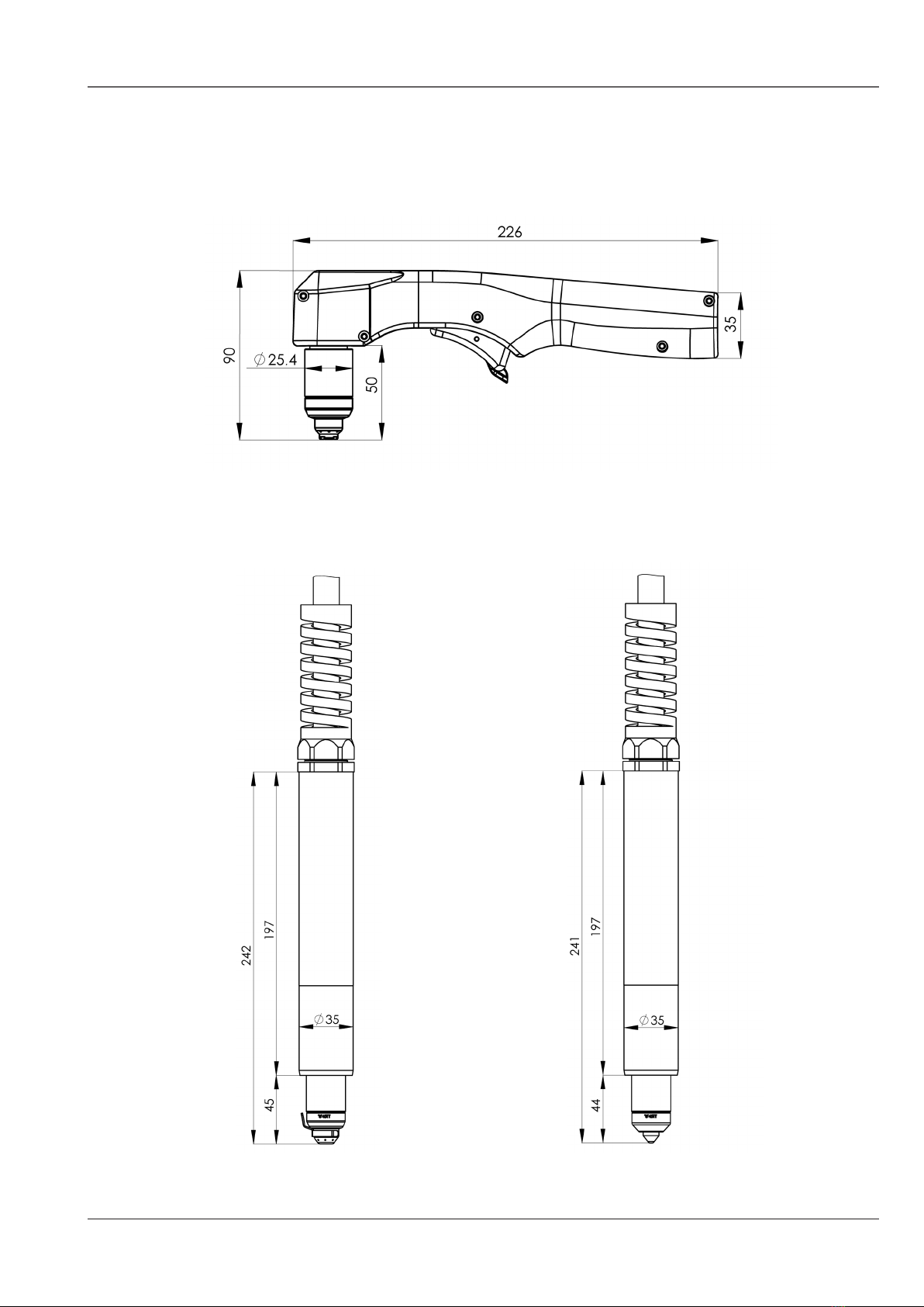
Machine torch FHT-EX®45TTM
Shielded configuration
using machine shield�
Dimensions and configuration
Shielded configuration using drag shield�
Unshielded configuration
using deflector�
Hand torch FHT-EX®45TTH
EX-TRAFIRE®45SD
Operator Manual, Revision T-52-16
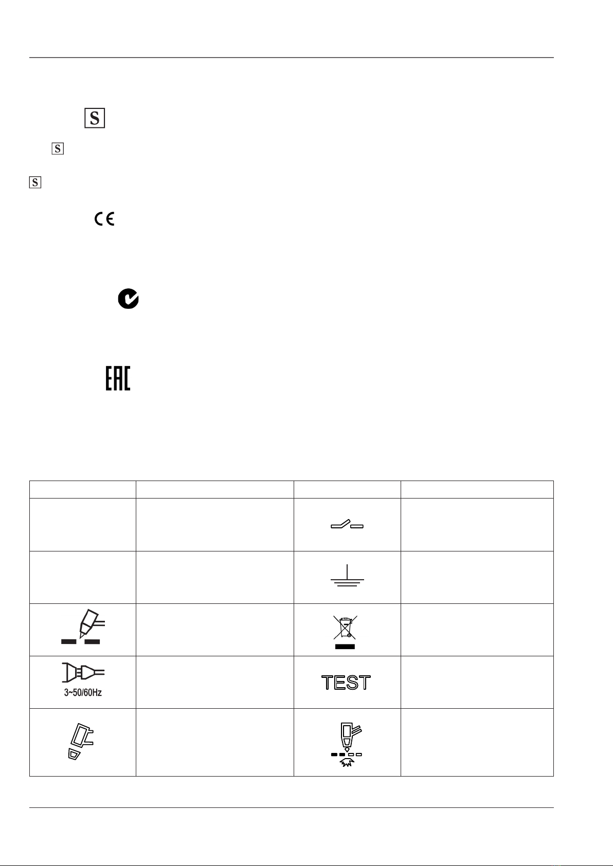
Symbols and marking
S Mark;
The mark indicates that the power supply and torch are suitable for use in environments with
danger of electrocution� The hand torches must have shielded consumable parts fitted to maintain
mark compliance�
CE Mark;
This marking signifies the manufacturer’s declaration of conformity to applicable European
directives and standards (EMC & LVD)�
C-Tick Mark;
This mark signifies compliance with appropriate Australian EMC standard�
EAC Mark;
This mark indicates products that conform to all technical regulations of the Eurasian Customs Union�
IEC symbols
Symbol Description Symbol Description
ON Power is ON BUS connector for further
IOT 4�0
OFF Power is OFF The terminal for the external
protective (earth) conductor
Plasma torch cutting Disposal of product
The terminal for the external
protective (earth) conductor Test mode
TIP/TORCH
Indicates the torch is connected�
Missing or loose nozzle
retaining cap�
Grid cutting mode
EX-TRAFIRE®45SD
Operator Manual, Revision T-5 2-17
3~ f1f2
1~ f1f2
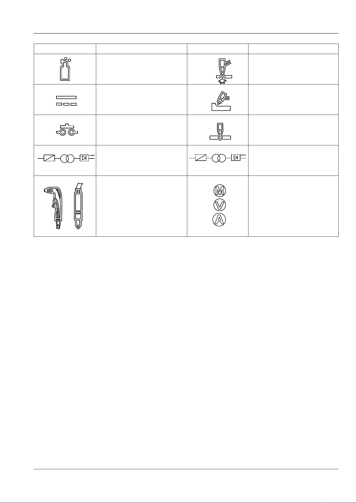
Symbol Description Symbol Description
GAS
Indicates flow of the gas�
Gas pressure fault�
Cutting mode
Direct Current (DC) power
The power supply is working� Gouging mode
Indicates pressing of torch
trigger or connection of pins
3, 4 in the CNC connector�
Indicates arc transfer
An inverter-based power
supply - 1-phase
An inverter-based power
supply - 3-phase
The torch type
PARAMETERS:
Meters
Volts
Ampers
3~ f1f2
1~ f1f2

EX-TRAFIRE®45SD
Operator Manual, Revision T-53-18
SECTION 3�
INSTALLATION:
SECTION 3: INSTALLATION
Upon receipt of goods���������������������������������������������������������������������������������������������������������3-19
Claims�������������������������������������������������������������������������������������������������������������������������������������3-19
Box contents��������������������������������������������������������������������������������������������������������������������������3-19
Power supply location ����������������������������������������������������������������������������������������������������������3-20
Mains power connection �����������������������������������������������������������������������������������������������������3-20
Connecting to an engine drive power generator�������������������������������������������������������������3-20
Grounding �����������������������������������������������������������������������������������������������������������������������������3-21
Mains power lead �����������������������������������������������������������������������������������������������������������������3-21
Single-phase mains power lead������������������������������������������������������������������������������������������3-21
Installation of single-phase mains power lead������������������������������������������������������������������3-22
Three-phase mains power lead ������������������������������������������������������������������������������������������3-22
Installation of three-phase mains power lead�������������������������������������������������������������������3-22
Torch installation step by step���������������������������������������������������������������������������������������������3-23
Working (ground) cable installation step by step�������������������������������������������������������������3-26
Plasma gas supply ����������������������������������������������������������������������������������������������������������������3-27
Additional gas filtration��������������������������������������������������������������������������������������������������������3-27
Gas supply regulation ����������������������������������������������������������������������������������������������������������3-28
Gas supply installation ���������������������������������������������������������������������������������������������������������3-28
System CNC interface connection��������������������������������������������������������������������������������������3-29
Activating an external DC coil with an external power supply ���������������������������������������3-30
Activating an external AC coil with an external power supply����������������������������������������3-30
Activating an industrial isolated module with an external power supply����������������������3-31
The circle cutting guide installation - for the FHT-EX®105RTXH/105TTH/45TTH���������3-32

EX-TRAFIRE®45SD
Operator Manual, Revision T-5 3-19
INSTALLATION
Upon receipt of goods
1� Verify that all ordered items have been received, for short shipment or damage to equipment,
contact the Authorized Supplier�
2� If there is evidence of damage, see Claims, below�
3� All communication relating to this plasma arc system should include the model and serial
number located on the bottom of the plasma arc power supply�
4� Read the information in the SAFETY section of this manual before installing and operating
the system�
Claims
Claims for shipping damage; If the unit has been damaged in transit, contact the carrier
immediately, take photographs of the packaging and areas of damage on the system� Inform
Authorized Supplier, who will provide copies of relevant documentation� For further assistance,
contact Customer Services, details are listed at the back of this manual�
Claims for defective or missing goods; All systems shipped from Authorized Supplier have been
subjected to a rigorous quality control procedure� If any of the parts are found to be defective or
missing, contact Authorized Supplier with the relevant information� For further assistance contact
Customer Services, details are listed at the back of this manual�
Box contents
Check the items that are shown in the illustration below� Packaging also includes an air line
connection DN7�2ES plug with male thread G1/4”�
CONSUMABLE
STARTER KIT
OPERATOR
MANUAL
or

EX-TRAFIRE®45SD
Operator Manual, Revision T-53-20
Power supply location
Place the plasma arc power supply EX-TRAFIRE®45SD on a flat even surface with a minimum
distance of 0�5 m of clear space all round to ensure good ventilation�
Mains power connection
The EX-TRAFIRE®45SD plasma arc power supply requires a 120 VAC ± 20% (CE) – 230 VAC ± 20%
(CE/C-TICK) single-phase mains power source or a 400 VAC ± 15% three-phase mains power
source� Use a circuit breaker for power line input so that the operator can turn off the power supply
quickly in an emergency� Locate the switch so that it is easily accessible to the operator� The interrupt
level of the switch must be equal to or exceed the continuous rating of the fuses� Use slow blow
fuses with a suitable capacity in accordance with local and national electrical codes�
Connecting to an engine drive power generator
When using an engine drive generator to power the EX-TRAFIRE®45SD:
Engine drive operation;
1� Set engine drive output to single or three-phase AC according to type of power supply�
2� Plug the EX-TRAFIRE®45SD mains power lead in to the power outlet�
3� Hard wire connection (No plug fitted) should be performed by a certified electrician�
4� Set the engine drive to maximum output (see chart below)�
5� For optimum performance, do not share the engine drive with other equipment such as
welding plant, lighting systems or angle grinders�
single-phase, three-phase, 50/60 Hz
Input voltage Engine drive rating Current output EX-TRAFIRE®45SD
Performance
120 VAC ± 20% 6 kW 25 A limited arc stretch
230 VAC ± 20% 10 kW 45 A full arc stretch
3 x 400 VAC ± 15% 10 kW 45 A full arc stretch
This manual suits for next models
1
Table of contents
Other THERMACUT Welding System manuals


Popular Welding System manuals by other brands


Migatronic
Migatronic SIGMA GALAXY Log book and instructions for use

Kühtreiber
Kühtreiber TIGER 255 Instructions for use and maintenance

Matco Tools
Matco Tools MP200STDVI owner's manual

WeldKing
WeldKing Mig Sonic 252S owner's manual

Kemppi
Kemppi Master S 400 quick guide

Miller
Miller Gold Star 500SSX owner's manual