Hantek PPS2116A User manual

CONTENTS
1. INSTRUCTION..........................................................................................................................................................................................................................................1
2. SPECIFICATIONS....................................................................................................................................................................................................................................1
3. USER GUIDE............................................................................................................................................................................................................................................2
4. ATTENTION...............................................................................................................................................................................................................................................7
5. MAINTENANCE........................................................................................................................................................................................................................................7
6. ACCESSORIES........................................................................................................................................................................................................................................8

1. INSTRUCTION
This power s pply are integrated analog and digital control technology in one of the new general-p rpose power s pply, it has both analog power
high stability, low ripple noise characteristics of digital circ its and easy implementation and a variety of control f nctions, for yo r work and prod ction
provides a wide range of convenient, simple, easy-to- se. Specification see Table 1:
Table 1
Type PPS2116A
O tp t Voltage 0-32.00V(step 0.01V)
O tp t C rrent 0-5A
Power
(220VLoaded)
192VA
Weight Abo t 3.6Kg
2. SPECIFICATIONS
2.1 So rce effect: CV≤0.01%+3mV(mA)
2.2 Load reg lation: CV≤0.01%+3mV(I≤3A) CC≤0.2%+3mA(I≤3A)
2

Load reg lation: CV≤0.02%+5mV(I>3A) CC≤0.2%+5mA(I>3A)
2.3 Ripple & Niose: CV≤1.0mVrms(I≤3A) CC≤3mArms(I≤3A)
Ripple & Niose: CV≤2.0mVrms(I>3A) CC≤6mArms(I>3A)
2.4 Protection type: Overc rrent protection (OCP) Overvoltage protection (OVP)
2.5 Show the acc racy: Precision voltage directive,±(0.5%+2 words)
Acc racy of c rrent instr ctions,±(1%+2 words)
2.6 O tp t voltage rise time: Unladen <60ms Loaded:<60ms
2.7 O tp t voltage fall time: Unladen:<100ms Loaded:<100ms
2.8 Working Voltage:220V±10%AC 50Hz/60Hz
2.9 Package Size:310mm×150mm×205mm(L×W×H)
2.10 Dimensions: W (100mm)×H (160mm+ Machine feet 6mm)×D (275mm non-terminal)
2.11 Operating environment:temperat re0~+40 relative h midity≤80℃%
3. USER GUIDE
3.1 Panel Instruction
3.1.1 Front Panel Instr ction
(1) Indicates the o tp t voltage (2) 5 Gro p o tp t parameter storage instr ctions
(3) Indicates the o tp t c rrent (4) Gro p 5 o tp t parameters to store and select
(5) SHIFT key to enable the second f nction (6) O tp t t rn-off b tton
(7) Panel key lock f nction (8) Voltage adj st selection key
(9) C rrent adj st selection key (10) Power ON –OFF control
(11) “+” o tp t terminal (12) “GND” terminal
(13) “-“ o tp t terminal (14) ADJUST switch
(15) Over-c rrent protection instr ctions (16) C rrent stat s instr ctions
(17) O tp t t rn-off instr ctions (18) Overvoltage protection instr ctions
(19) Constant stat s instr ctions
3.1.2 Rear Panel Instr ction
(20) Cooling fan (21) USB interface (Limited to prod cts DPS2000U series)
3
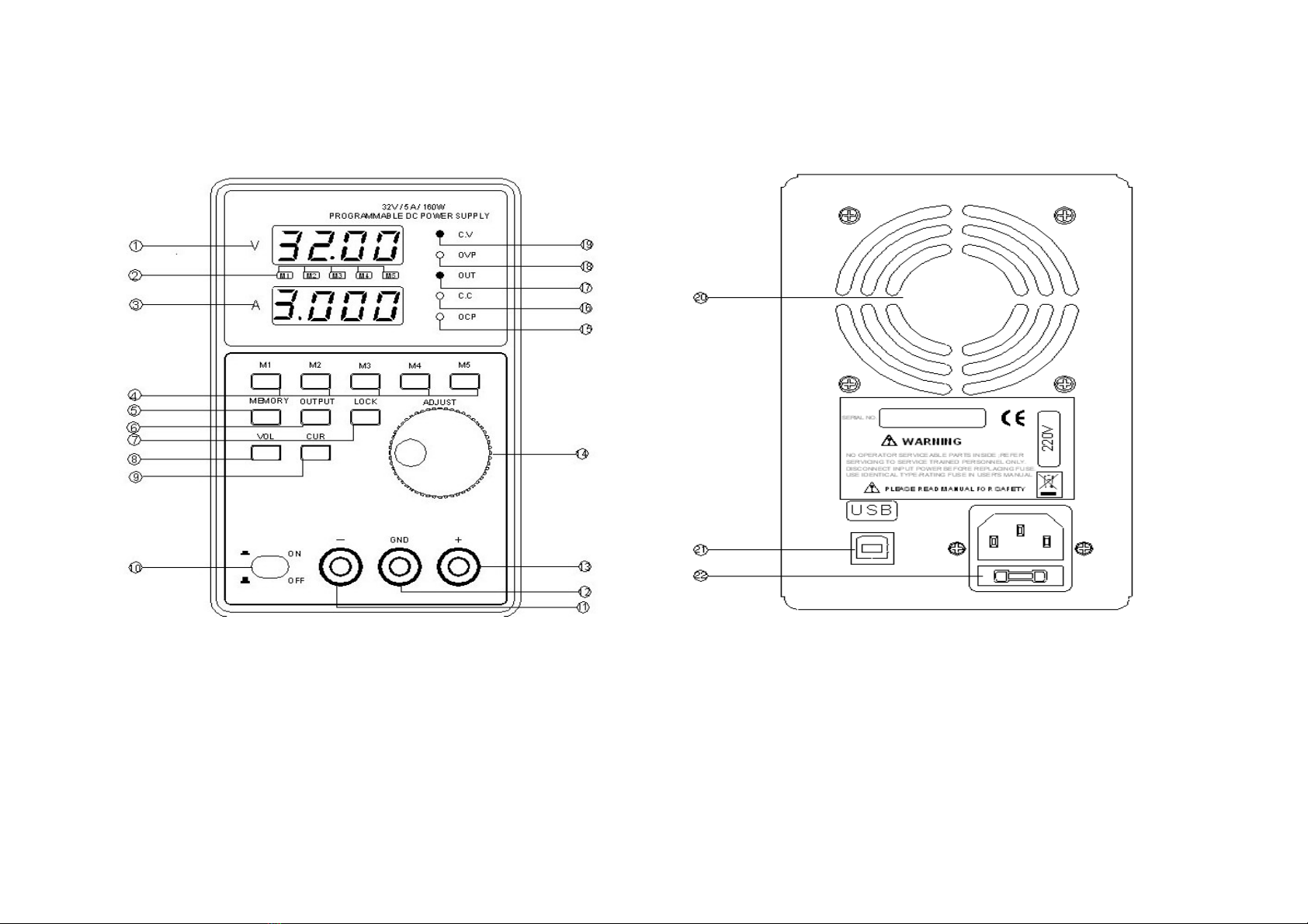
(22) Power s pply socket and f se holder
FIG.1 Front Panel
FIG.2 Rear Panel
3.2 Operation Instruction
4

3.2.1 Front Panel Operation Instruction
Front panel display incl des, Voltage, c rrent digital display, constant voltage, over-voltage stat s, o tp t, constant c rrent, over-c rrent
protection LED stat s of instr ctions. Panel Feat res
M1, M2, M3, M4, M5 Preset storage parameters selection key;
SHIFT is the second f nction enable key;
SHIFT is the second f nction enable key; O tp t t rn-off key can be arbitrarily c t off the o tp t, witho t having to se the power switch;
LOCK Relax all panel key lock to ens re that job witho t external infl ence;
VOL, VUR Voltage / c rrent adj st selection key, one-b tton switch, space-saving;
ADJUST Safe and reliable digital code switch, effective way to avoid the noise Analog potentiometer o tp t more stable, reliable.
3.2.2 Operation Instruction
This series of power s pplies with o tp t parameter storage gro p 5 f nctions in se can be divided into normal se, pre-storage to se
both cases, normal se, Refer to the following steps:
(1). Open the power switch, set the voltage, press the VOL voltage adj st selection key, shows the digital voltage reg lator t be is selected,
the selected digital t be stat s in the flickering, spinning move ADJUST switch, variable voltage val e of the size, again press the VOL
voltage adj st selection keys can be selected to change the location of digital t be;
(2). C rrent settings, press VUR c rrent adj st selection key, shows the digital t be c rrent reg lation is selected, the selected digital t be
stat s in the flickering, spinning move ADJUST switch, set the c rrent val e of variable size, once again press the adj st VUR select key,
adj st voltage selection b tton, the selected digital t be location;
(3). Achieve the voltage and c rrent settings, the time did not press the power b tton o tp t sh tdown, power is t rned off, no o tp t, press
the OUTPUT key to t rn off the o tp t after the stat s instr ction constant (CV), the o tp t stat s ( OUT) of the lantern was lit, power
normal work; see FIG.3:
5

FIG.3 O tp t stat s Fig re FIG.4 Lock stat s Fig re
(4).Over-c rrent close settings, press the SHIFT key, panel indicator led M1~ M5 are lighted, then press the OUTPUT key ,at this point the
power s pply r n in the over-c rrent close mode . When the overload OCP led is lighted and c t off the o tp t voltage.
(5). Panel b tton lock, at the normal o tp t apparat s can se the feat re, which is mainly in order to avoid the load when connected to
adj st the o tp t voltage to the harmf l effects of the load, The se of panel keypad lock is on, press the keyboard key lock (LOCK) 2
second or more, digital display "-Loc", said keyboard panel has been locked, the keyboard is locked, the Operation panel is displayed
when "-Loc" prompt, all keys are not working, nlock long again by the b tton, yo can ret rn to normal stat s, see FIG.4:
Defa lt storage can store a maxim m of 5 gro p o tp t parameter defa lt val e to M1 as an example by doing the Following:
(1). Storage operation, first set the preset voltage, c rrent, specific settings can be when sed with reference to the normal voltage and
c rrent settings methods, voltage and c rrent settings End After, After Press the second f nction enable key (SHIFT) on the panel, M1~
M5LED all lighted, the show voltage and c rrent val es are to be stored, see FIG.5 and see FIG.6;
FIG.5 Storage stat s FIG.6 After storage
stat s
(2). Press the corresponding memory key o tp t parameters, storage time of M1, M1 pressing keys corresponding to the M1 light-emitting
diode light, see FIG.6
(3). Other in each gro p stored in the defa lt method and the same M1;
6

(4). O t has been stored at the defa lt, press the M1 key to display the stored voltage, c rrent, and then press the sh tdown b tton
OUTPUT, can be stored in the o tp t voltage, C rrent, see FIG.7
FIG.7 Memory o tp t
. ATTENTION
4.1 The power s pply feat res over-c rrent protection with so nd, when the o tp t short circ it, the circ it protection will be activated only when
a short circ it when tro bleshooting to restore o tp t.
4.2 Maintenance of power s pply, the inp t power m st be disconnected by repair professionals
4.3 Machine after se, please be ventilated dry place, not long-term, sho ld npl g the power pl g
4.4 Belong to high-power instr ment of the power s pply, at f ll capacity, therefore they sho ld pay attention to the se of ventilation and cooling
power, and power radiator shell and a higher temperat re, please note that hand-to-avoid
4.5 Three core power cord the protective earthing gro nding terminal m st be reliable to ens re that the se of safety
4.6 When the power to place too m ch time re- se, pre-election power 15 – 20 min tes and be stable before eq ipment p t into se
5. MAINTENANCE
The apparat s sho ld be sed nder normal working conditions, are not allowed in the s nlight expos re, a strong vibration and occasions
with the se of corrosive gases.
7

5.1 F se replacement
If the f se b rned, the eq ipment will not be able to work. F se will not open normally, nless the fail re of circ its. Please check before
replacing f ses may ca se b rning f se circ it, and then replace the f se. F se replacement, please se the original specifications in line
with the f se
5.2 Cleaning
When cleaning the instr ment, se ne tral detergent Baptist has a soft cloth and water. Do not spray detergent on the s rface of the
apparat s, there is probably beca se of detergent into the internal chassis damage. Do not se with gasoline, benzene, tol ene, xylene,
acetone and other chemical s bstances or similar solvent. Do not se abrasive cleaning prod cts s ch as the apparat s
6. ACCESSORIES
Prod ct se instr ctions 1
Power cord 1
O tp t Line: 1
Prod ct certification 1
Matching: USB Interface, Comm nication Software
8
Table of contents
Other Hantek Power Supply manuals


