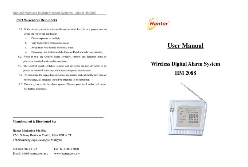
Hanter HM2078 User manual

7. General Reminders
Manufactured & Distributed by:
Hanter Marketing Sdn Bhd (717180-X)
12-3, Subang Business Centre, Jalan USJ 9/ 5T
47620 Subang Jaya, Selangor, Malaysia
Tel: 03 8023 4122 Fax: 03 8023 3028
Email: info@hanter.com.my www.hanter.com.my
User Manual
Wireless Intelligent Alarm System
HM2078
Hanter® Wireless Intelligent Alarm Systems - Model HM2078
7.1 If the alarm system is temporarily not in used, keep it in a proper area to avoid
the following conditions:
a. Direct exposure to sunlight
b. Very high or low temperature areas
c. Away from very humid and dusty areas
d. Disconnect the batteries of the Control Panel and other accessories.
7.2 When in use, the Control Panel, switches, sensors and detectors must be placed
or installed under stable conditions.
7.3 The Control Panel, switches, sensors and detectors are not advisable to be
placed or installed at the area with heavy magnetic interference.
7.4 To maximize the signal transmission, accuracy, and extend the life span of the
batteries, all antennas should be extended to the maximum.
7.5 Do not try to repair the alarm system. It will affect the validity of your warranty.
Consult your local authorized dealer.

Item Issues Possible Cause Solution
12 Unable to activate Long
Distance Remote
Control the Control
Panel via Telephone
Key in wrong Password Key in password again.
Password keyed in too fast Key in password slowly.
13 Additional detector
unable to match the
coding with Control
Panel
The frequency of the detector
is different from Control Panel
Make sure both detector and
Control Panel is same frequency
The coding chips of detector is
not compatible with Control
Panel
Make sure the coding chips of
detector is compatible.
14 Control Panel disarm
automatically
Control Panel accidentally saved
signal that can cause interference
Erase it and reset
The disarm button of Keychain
Remote Control has been
depressed.
Release the depressed disarm
button
15 Control Panel
occasionally trigger false
alarm
Motion Sensor located at the
area near to pets activities.
Re-adjust the motion sensor
location.
Motion Sensor located at the
area near to window that is
heavy in air circulation.
Re-adjust the motion sensor
location
16 Unable disarm by
Keychain Remote
Control or need to
shorten the distance to
disarm
The Control Panel is in the
process of auto-dialing
Wait till it finishes auto-dial then
you may disarm
Keychain Remote Control
battery is low energy
Change the battery
P. 15
Contents
1. System Overview
2. System Workflow
3. Functions and Features
4. Units Descriptions
5. System Installation, Settings
and Operations
6. Trouble Shooting
7. General Reminders
Acknowledgement:
Thank you for choosing our Home/Commercial Wireless Intelligent Alarm System.
To achieve optimum performance of the system, kindly read the manual.
P. 2
Hanter® Wireless Intelligent Alarm Systems - Model HM2078 Hanter® Wireless IntelligentAlarm Systems - Model HM2078

2. System Workflow
Remote controlling
------HM2078
Item Issues Possible Cause Solution
6 Alarm is triggered but the
alarm LED light is not on
Telephone line to Control Panel
may not be connected properly
Ensure the telephone line to
Control Panel is well
connected
The preset auto-dial number is not
programmed
Program the preset auto-dial
numbers
7 Control Panel can
auto-dial to preset mobile
phone numbers, but the
success calls rate is
inconsistent
The telephone line connected to
Control Panel is over loaded with
too much extension lines
Change to a non extension
telephone line.
The reception signal of the mobile
phone set is not stable.
Change it to fixed telephone
line or new mobile phone set.
8 Control Panel can
auto-dial to preset mobile
phone numbers, but the
success calls rate is
inconsistent
The telephone line connected to
Control Panel is over loaded with
too much extension lines
Change to a non extension
telephone line.
The reception signal of the mobile
phone set is not stable.
Change it to fixed telephone
line or new mobile phone set.
9 Control Panel can
auto-dial preset telephone
number but cannot
activate the siren
Activated the SilentAlarm feature.
(For Model 2088 series onward)
Deactivate the Silent Alarm
feature.
The siren jack not plug-in properly Plug the siren jack properly.
10 Alarming LED light
always on
Control Panel not disarmed
properly
Disarm again.
11 No voice message when
receive telephone call.
The telephone line connected to
Control Panel is over loaded
Use a non-extension
telephone line
P. 14
1. System Overview
The newly developed alarm series, Homes/Commercial Digital Wireless Intelligent
Alarm System Model HM2078 has a Micro-Processor Chip and Wireless RF Control
Technology to ensure the reliabilities, easy installation and operation of the system.
The system consists of a Control Panel that can be installed inside any hidden area of
the office or home, and the monitoring sensors such as Wireless Infrared Motion
Sensor, Wireless Door/Window Magnetic Switch, Wireless Smoke Detector and
Wireless Gas Leak Detector etc. are mounted on the spots that require monitoring.
When the system is armed, any of the sensors/switches/detectors detects a signal will
wirelessly transmit signal to the Control Panel. It will then trigger the siren and
immediately autodial the preset phone numbers and transmits the pre-recorded alarm
voice message to the phone owner. When the alarm signal received, the owner can
take the appropriate actions or report to the police accordingly. All processes will
only take a few tens of seconds.
The additional feature is in case of an emergency at home for the aged persons or
children, the Emergency Help Button can be pressed to activate the autodialing
pre-set telephone to ask for help. The Alarm System will guard your home when you
are away or resting.
P. 3
Hanter® Wireless Intelligent Alarm Systems - Model HM2078 Hanter® Wireless Intelligent Alarm Systems - Model HM2078

2. System Workflow
Long Distance Remote Controlling
Transmission Notification
Emergency Arm/ Disarm Alarm
Help
Pager
Mobile
p
hone
Telephone
Motion Sensor
Smoke Detector
Gas Leak
Detector
Siren
Keychain
Remote Control
Glass Break
Detector
Emergency
Help Button
Control Panel
(HM2078)
Door / window
Switch
3. Functions and Features
3.1 Functions
3.1.1 Arming & disarming by Keychain Remote Control
3.1.2 Long distance remote control by any telephone
3.1.3 Alarm siren buzzing to warn for illegal intrusion or possible intrusion
3.1.4 Alarm reporting on illegal entries by PIR Motion Sensor and Magnetic Door /
window Switches
3.1.5 Smoke & fire alarm
3.1.6 Toxic gas leaking alarm
3.1.7 Auto dialing to preset phone numbers for alarm notification
3.2 Features
3.2.1 Easy installation and simple operation
3.2.2 Tampers proof system on telephone line being cut
3.2.3 Priority calling when alarm triggered
3.2.4 Data input will be retained when power failure
3.2.5 Accessories expandable up to a maximum 99 points and paired with fixed code
P. 4
Other Sensors
& Detectors
6. Trouble Shooting
Item Issues Possible Cause Solution
1 Telephone line is in working
condition, but unable to
make call to preset telephone
numbers when alarm is
triggered.
Telephone line to Control Panel
may not be connected properly
Ensure the telephone line to
Control Panel is well connected
Pre-set auto-dial numbers is not
properly programmed.
Program the preset auto-dial
numbers in accordance to the
user manual.
2 Control Panel trigger siren
immediately while enter
arming status, but no
auto-dial was made.
Telephone line to Control Panel
may not be connected properly.
(Activated the anti-cut function)
Ensure the telephone line to
Control Panel is well connected
3 Control Panel is in working
condition, but the detector
has no response
The batteries energy of detector is
low.
Change batteries
Interference of external signals Test the Control Panel and
detector in close range
The battery is not well connected Reinstall the battery or clean
the battery contact point
4 During the disarming status,
siren triggered and auto-dial
the preset telephone numbers
One of the detectors might coded
with Emergency Mode coding
Reset the coding of the detector
according to the type of
detector
Control Panel saved signal that can
cause interference
Delete the saved signal of the
Control Panel and reset the
coding of detectors
5 No response from Control
Panel when power is on
The power supply is not well
connected or not in working
condition,
Reconnect the power supply
and make sure it plug-in to right
port or change the new adapter.
P. 13
Hanter® Wireless Intelligent Alarm Systems - Model HM2078 Hanter® Wireless IntelligentAlarm Systems - Model HM2078

------HM2068
4. Unit Descriptions
4.1 Standard Accessories:
4.1.1 Control Panel
Control Panel is the device to receive signal from sensors, switches and detectors.
Once a signal is being received, it will immediately trigger the alarm via the
siren and call the preset telephone line simultaneously for alarm notification.
a.Panel Board illustration
b. LED indicator light on Control Panel Board (from left to right)
● Arm: Away Arm – the LED is lighted
Home Arm – the LED light will flash
● Alarm: The LED light is on when alarm is triggered
● Low Voltage: The LED light is on, when voltage is low, need to change
the back-up battery
● Power: The light is on, when power on
c. Back-Up Batteries
Slide off the cover at the back of the Control Panel. Place the battery into the
battery compartment, then close the cover plate. Do not make any short
connection of the battery terminals under any circumstances. The battery can
provide about 36 hours of power to the Control Panel when the power down.
4.1.2 Keychain Remote Control
The Keychain Remote Control can be used to operate the Control Panel.
P. 5
5.3.6 Notification (when away from premise)
When the alarm is triggered, the user (pre-set number) will receive a call with the
pre recorded voice message. The option/ next course of action are:
a. Press the “#” key of your phone to stop the siren.
b. Ignored it, the siren will continue and the Control Panel will auto dial the next
pre-set numbers according to priority.
c. The process of auto-dialing will continue until someone acknowledges it with
“#” key.
Reminder: Should you be away for long period of time and cannot be reached, it is
advisable to set numbers based on your other priority of pre-set number.
5.3.7 IdentifyingAlarm Message by Incoming Call
a. Double “Beep” every 2 seconds means Smoke alarm
b. Single “Beep” every 2 seconds means Gas Leakage alarm
c. No sound (except for voice message announcement) indicates that the alarm is
triggered by Door Switch, Motion Sensor or Emergency Help Button to
confirm password.
5.3.8 Long Distance Remote Control
Step 1: Dial the Telephone number connected with the Control Panel.
Step 2: After 8 ringing tones, a five beeping sound will be heard
Step 3: Enter the Password. Another five beeping sound will be heard to confirm
password.
Step 4: Press “0” to stop siren, Press “1” to start siren, Press “4” for Disarm/
Home Arm or Press “5” forAway Arm.
Step 5: Press “#” to exit from program.
Reminder: It will not work if someone picks up the telephone immediately. If you key
in wrong password (3 times), the line will be disconnected automatically.
P. 12
Hanter® Wireless IntelligentAlarm Systems - Model HM2078Hanter® Wireless Intelligent Alarm Systems - Model HM2078
5“Beep” Enter3times
invalid password
Press “2”
Press “3”
Dial
Telephone
8 rin
g
in
g
Enter
Password
Line disconnected, Exit
5
“
Beep
”
Exit
Sto
p
Siren
Start Siren
Home
Arm
Awa
y
A
r
m
Press “0”
Press “1”
Press “#”
Press“4”
Press“5”

Functions are as following:
4.1.3 Indoor Wired Siren
When alarm system is in alarm mode, the siren will emit a loud sound of 110db. It
can be installed on any location with enclosed adhesive tape or screws and connect it
to siren port of Control Panel.
Note: The duration of the alarm sound from Siren is approximately 12 minutes to
ensure this duration of siren, you must program 6 sets of pre-set telephone numbers.
4.1.4 Wireless Magnetic Door/Window Switch
It consists of 2-piece unit. You can locate the switch unit and magnet bar onto two
frames of the door or window. When the door or window frames are separated, i.e. the
switch unit and the magnet bar are separated, the switch unit will send the signal to
the Control Panel to trigger the alarm siren and then auto dial the pre-set phone
numbers.
4.1.5 Wireless Motion Sensor (PIR)
The wireless Motion Sensor adopts wireless digital and microprocessor technology
with low energy consumption design. The core technology of the infrared detector,
the operational amplifier chip, employs specially designed mask (three sets of built-in
operational amplifier, capable of processing digital and analog signals
simultaneously), which makes it a highly intelligent detector with wireless
transmission of digital signals combined with low energy consumption.
4.2 Optional Accessories
4.2.1 Wireless Smoke Detector
The Wireless Smoke Detector is widely used in professional security & protection
alarm system. It will send RF signal to the Control Panel when it detects smoke. It is
recommended to locate this unit at a less or non-smoke area.
4.2.2 Wireless Gas Leak Detector
The Wireless Gas Leak Detector is widely used in professional security & protection
alarm system. It will send RF signal to the Control Panel when it detects natural gas,
piping coal gas and liquefied petroleum gas etc.
4.2.3 Wireless Emergency Help Button
The Wireless Emergency Help Button is a wireless Remote Control Unit. In the event
of emergency, just press the Emergency Help Button.
P. 6
5.2.3 Voice Message Recording
Step 1: Press “” key of the Keychain Remote Control
Step 2: Press and Hold the Program Key
Step 3: Start recording when alarming LED is light
Step 4: Record 10 second voice message into “Record’ port of the control Panel
(Bottom right) Sample of message: “Help! Help! Help! Alarm is triggered
at No 86, Jalan SS2/33, Petaling Jaya, please help!”
Step 5: Release the Program key
Note: The message can be re-recorded anytime by following the above steps. Any
languages can be used to suit your practicality, as long as the voice projection
are loud and clear.
5.3 Operations
5.3.1 AwayArm:
Press of the Keychain Remote Control, a “beep” sound will acknowledge
successful of fully arming.
a. Smoke and Gas Leak Detector will be on arming mode instantly.
b. Magnetic Door/Window Switch and Motion Sensor need approximately 30
second to enter arming mode. This is to allow the user to have enough time to
leave the monitored or detected area.
c. The Arm LED will light after 30 seconds.
5.3.2 Home Arm
Press of the Keychain Remote Control, a “beep, beep” sound will
acknowledge successful of partial arming. In the partial arming, the Control
Panel will not receive any signal from Magnetic Door/Window Switch and
Motion Sensor. However it will receive signal from the Smoke and Gas Leak
Detector which are still in arming status.
3
5.3.3 Disarm
Press “” key of Keychain Remote Control to enter disarming status, a “beep,
beep” sound will acknowledge successful disarming and the Control Panel will
not receive any signal from Magnetic Door/Window Switch, sensors and
detectors, except signal from Emergency Help Button.
5.3.4 Emergency Help
Press ;U Key of the Keychain Remote Control, the Control Panel will
automatically trigger the siren and immediately autodial to the pre-set
telephone numbers.
Note:
When the alarm is triggered, the siren cannot be stopped immediately by
pressing “” key of the Keychain Remote Control. It is because our intelligent
alarm system will stop all functions and give priority to call the pre set
telephone numbers. The siren can be disarmed after 5 – 10 seconds.
5.3.5 Anti-cut
During armed status, if the telephone line is cut, the Control Panel will
automatically trigger the siren.
Note: This feature will not be practical if your telephone is unstable.
P. 11
- Away Arm
- HomeArm (for Smoke &
Gas Leak Detector only)
- Disarm
;U - Emergency Help
Hanter® Wireless Intelligent Alarm Systems - Model HM2078Hanter® Wireless Intelligent Alarm Systems - Model HM2078

4.2.4 Wireless Glass Break Detector
The Glass Break Detector delivers effective coverage in the presence of plate,
tampered, and laminated glass, with easy sensitivity adjustment. The optimal
performance is dependent on the secured and vibration-free mountings. The
Glass Break Detector can be used in most protected areas, including glass
display panel and rooms with blinds, curtains, or multiple windows, as long as
careful coverage tests are conducted.
5. System installation, Settings and Operations
5.1 System Installation
5.1.1 Control Panel
The Control Panel can be placed or install on desk or on the wall (preferably a hidden
spot but easily accessible)
Step 1: Connect the AC adapter. Insert the adapter jack to the “9V 300mA” port
of the Control Panel. Then plug in the AC adapter into an electrical
source
Step 2: Connect an incoming Telephone line to “Line in” port
Step 3: Connect desktop telephone set to “Telephone” port
Step 4: Insert the Siren jack into the “Siren” port.
Reminder:
In order to ensure the alarm system operate properly, all the above cables must be
well connected.
5.1.2 Wireless Magnetic Door/Window Switch
The Wireless Magnetic Door/Window Switch is equipped with a magnet bar
(movement of the magnet triggers an internal sensor in the switch). We
recommend locating the switch unit on the wall at the frame of the door or
window, with the magnet bar on the moving part of the door or window.
Step 1: Open the switch’s cover by screwdriver
Step 2: Install the switch to the desired location, using the two screws or
adhesive tape
Step 3: Ensure the antenna is vertical (pointing up or down).
P. 7
Step 4: Lift up the handset of Telephone unit
Step 5: Press 0128881234*1# on the keypad of telephone unit
Step 6: The control Panel will emit 3 Beeping sound to confirm successfully
programming
Step 7: Repeat the same steps for the balances 2nd, 3rd, 4th, 5th & 6th set of telephone
numbers.
b. To Program Telephone Number on extension line
Just by adding “0” or “9” (depend on telephone system setting) in front of each
telephone number.
Example: To set 0128881234 as 1st set of Telephone Number on telephone system
that need press 9
Step 1: Press the “” key of the Keychain Remote Control
Step 2: Press Program Key on the Control Panel
Step 3: Alarming LED will light
Step 4: Lift up the handset of Telephone unit
Step 5: Press 90128881234*1# on the keypad of Telephone unit
Step 6: The control Panel will emit 3 Beeping sound to confirm successfully
programming .
Step 7: Repeat the same steps for the balances 2nd, 3rd, 4th, 5th & 6th set of telephone
numbers.
c. To delete the Stored Telephone Number
Example: To delete 0128881234 as 1st set of Telephone Number.
Step 1: Press the “” key of the Keychain Remote Control
Step 2: Press Program Key on the Control Panel
Step 3: Alarming LED will light
Step 4: Lift up the handset of Telephone unit
Step 5: Press *1# on the keypad of Telephone unit
Step 6: The control Panel will emit 3 Beeping sound to confirm successfully
programming.
Note: When there is an error during entry of telephone number, press “#” to exit
and reset.
5.2.2 Password setting
The default password is “1234”, you may change this password according to the
following steps.
Step 1: Press “” key of the Keychain Remote Control
Step 2: Lift up the handset of Telephone unit
Step 3: Press Program Key on the Control Panel
Step 4: Alarming LED will light
Step 5: Key in your “new password” (total 4 digitals) and follow by “*0#”
on the keypad of telephone unit
Step 6: The control Panel will emit 3 Beeping sound to confirm successfully
programming. .
Note: The password can be reset anytime.
P. 10
Hanter® Wireless IntelligentAlarm Systems - Model HM2078Hanter® Wireless Intelligent Alarm Systems - Model HM2078
Line in Telephone

Press “#” to exit
remote control settin
g
------HM2078
Step 4: Attach the magnet bar using the screws or adhesive tape to the moving
part of the door or window. The gap between the switch and magnet bar
should not be wider than 1.5cm when the door is closed.
Step 5: Opening and closing of the door/window will be confirmed by the
switch’s LED.
Reminder:
If the switch or magnetic bar is fix directly on a metal surface, one is advisable to
pre-attach an insulator (plastic piece) in order not to affect the signal transmission
strength of the units.
5.1.3 Wireless Motion Sensor (PIR)
Step 1: Pry off the back plate with a small screwdriver, and install the provided
battery into the back of PIR detector.
Step 2: Mount the bracket with screws provided at any place you think has the
best coverage by the PIR sensor. Recommended height is about 2.1
meters above the floor.
Step 3: Mount the PIR sensor onto the bracket. The maximum distance coverage
area is up to 12 meters, and it has a detection angle of: 120 degree
horizontally, 60 degree vertically.
Reminder:
Do not place the detector close to any heating/cooling vents or near any other
object that often changes temperature.
The PIR detector should not be placed near any item that generates a strong
electromagnetic signal. (transmitters, electronic regulators etc.). Avoid locations
that have intense air circulation.
5.1.4 Wireless Smoke Detector
Step 1: Install the detector to the desired location.
Step 2: Drill two holes on the wall or ceiling per the whole sizes of the mounting.
Bracket.
Step 3: Fix the mounting bracket on the wall or ceiling with the screws.
Step 4: Twist and lock the detector with the mounting bracket.
Step 5: Do not try to open the unit by yourself. You should only pry off the back
plate and install the battery.
Step 6: Press the test button to confirm that the installation is successful.
5.1.5 Wireless Gas Leak Detector
a. Install the detector per the density of gas.
•For the Natural gas and piping coal gases lighter than air, install it close to the
ceiling (lower 0.3~1.2 meters).
•For the liquefied petroleum gases (LPG) which is heavier than air, install it close to
the floor (higher than 0.3 to 1.2 meters and inside the range of gas source with
direct 1.5 meters).
P. 8
b. The detector should not be located near any areas that emit gas (cooking area).
c. The detector should not be located close to any obstacles (curtain or cabinet etc.)
d. The detector should not be located in the bathroom or any area with too much
vapor.
5.1.6 Coding/ Pairing
The accessories have been coded with the Control Panel and it is ready to be used
directly. The Coding/pairing function is only applicable for additional or new
Keychain Remote control, Magnetic Door/Window Switches, Motion Sensors and
other accessories.
a. Keychain Remote Control
Step 1: Open the cover of the existing unit
Step 2: Open the cover of the new unit
Step 3: Solder the new remote control based on the codes from the existing
remote control
b. Wireless Magnetic Door/Window Switch
Step 1: Open the cover of the existing unit
Step 2: Open the cover of the new unit
Step 3: Make the coding at new unit according to the code from existing unit
c.
Sensor or other detectors
Step 1: Open the cover of the existing unit
Step 2: Open the cover of the new unit
Step 3: Ensure the codes are the same as the existing one, by adjusting the code
to the new one
Reminder:
Should you face any difficulties, please refer to your local supplier.
5.2 System Settings (all functions settings must be under Disarming Status)
5.2.1 To Program Telephone Numbers (maximum 6 sets of numbers)
Press the “” key of the Keychain Remote Control to enter disarming status, then
press Program Key on the Control Panel. When the arming LED light appear, pick
up the telephone handset and input the designated telephone numbers follow by
input *1#, repeat same process for the 2nd set pre-set number and end with *2#.
The rest are the same except for signing off with *3#, *4#, *5# and *6#
respectively after each entry. *1# is memory No 1, *2# is memory No 2 and so on.
Note: With the completing program the 6 set of numbers will maximize the duration
of Alarm Buzzing to approximately 12 minutes.
a. To Program Telephone Number
Example: To set 0128881234 as 1st set of Telephone Number
Step 1: Press the “” key of the Keychain Remote Control
Step 2: Press Program Key on the Control Panel
Step 3: Alarming LED will light
P. 9
Hanter® Wireless Intelligent Alarm Systems - Model HM2078Hanter® Wireless Intelligent Alarm Systems - Model HM2078
Table of contents
Other Hanter Security System manuals
Popular Security System manuals by other brands
Dolphin
Dolphin BC5083-120 Installation and maintenance guide
ProCurve
ProCurve J8462A quick start guide
Assa Abloy
Assa Abloy effeff EXITalarm Mounting and operating instructions

Politec
Politec ALES Series installation manual

ADEMCO
ADEMCO VISTA-50P quick start

ROBBERSTOPPER
ROBBERSTOPPER PEPPERALARM operating instructions
