IPM IP02 Series User manual

810201,810202,810203,810204
IP02 SERIES
2:1 RATIO TRANSFER PUMP
OPERATIONING MANUAL
WITH
PARTS IDENTIFICATION
IPM, INC.
Manufactured by International Pump Manufacturing, Inc.

2
IP02 series
2:1 RATIO TRANSFER PUMP
OPERATIONS MANUAL and
PARTS IDENTIFICATION DRAWINGS
This manual contains IMPORTANT WARNINGS and INSTRUCTIONS. Read and retain for future reference.
INTERNATIONAL PUMP MANUFACTURING, INC.
3107 142nd Avenue E Suite 106,
Sumner, WA 98390
U.S.A.
TEL: (253) 863 2222
FAX: (253) 863 2223
Website :
www.ipmpumps.com
For Technical Service Call Your Local Distributor
Copyright 2016 by: International Pump Mfg, Inc.
WARNING: The equipment described herein must only be operated or
serviced by properly trained individuals thoroughly familiar with the
operating instructions, mechanics and limitations of the equipment.
Notice: All statements, information and data given herein are believed to be accurate and reliable but are presented without guarantee,
warranty or responsibility of any kind expressed or implied. Statements or suggestions concerning possible use of IPM equipment are
made without representation or warranty that any such use is free of patent infringement, and are not recommendations to infringe any
patent. The user should not assume that all safety measures are indicated or that other measures may not be required.

3
TABLE OF CONTENTS
1.0 SAFETY WARNINGS
4
2.0 INSTALLATION 8
2.1 Installation procedures 9
3.0 OPERATION 10
3.1 Start up and adjustment of transfer pump 10
3.2 Shut down procedure 10
4.0 MAINTENANCE AND REPAIR 11
4.1 Air motor section disassembly 11
4.2 Air motor section assembly 13
4.3 Fluid section disassembly 14
4.4 Securing the fluid section to the air motor section 16
5.0 PARTS IDENTIFICATION 17
5.1 Parts drawing for air motor section of 810201,810203
17
5.2 Parts drawing for fluid section of 810201 18
5.3 Parts drawing for fluid section of 810203 19
5.4 Parts drawing for air motor section of 810202,810204
20
5.5 Parts drawing for fluid section of 810202 21
5.6 Parts drawing for fluid section of 810204 22
6.0 REPAIR KITS 23
7.0 TROUBLESHOOTING 24
8.0 TECHNICAL SPECIFICATIONS 25
9.0 WARRANTYAND DISCLAIMER 27

4
1.0 SAFETY WARNINGS
Please read and observe all warnings contained in this operations manual before making
any attempt to operate the equipment.
Misuse of equipment
Misuse of equipment can cause serious bodily injury. Use the equipment only for its
intended purpose and do not attempt to modify it in any way. Care should be taken to
prevent over pressurization of the pump, hose lines and accessories connected to it. Use
only IPM designated parts for re-building or repairing this equipment. Use the pump only
with compatible fluids. Improper use of this equipment could result in fluid being sprayed
on the skin or in the eyes of user, serious bodily injury, property damage, fire or explosion.
D
aily maintenance inspection should be made on pumps and equipment and all worn or
damaged parts should be re-placed immediately. Do not use pumps, components or
hose lines as leverage to move equipment to avoid damage and injury.
Do not alter this equipment as doing so could cause it to function incorrectly and/or cause
serious injury. Altering this equipment in any way will also void any and all warranty
guarantees from the manufacturer.
Material & fluid compatibility
Always ensure the chemical compatibility of the fluids and solvents used in the fluid
section of these pumps, hoses other components. Check the chemical manufacturer’s
data sheets and specification charts before using fluids or solvents in this pump to ensure
compatibility with pumps, inner hose lining and outer hose covering.
Warning
To reduce the risk of static sparking or splashing fluid in the eyes or on the skin,
follow the Pressure Relief Procedure before flushing.
For your safety, read the Fire or Explosion Hazard before flushing and follow all the
listed recommendations.

5
Pressurized hoses
Because the hoses are pressurized they can present a danger should the fluid escape due
to damage, worn parts or general miss-use. Escaping fluid can splash or spray operator,
causing serious bodily injury and/or damage to equipment and property. Ensure that the
hoses do not leak or rupture due to wear, misuse or damage.
Before each use, ensure that the fluid couplings are tight and all clips/pins/plugs are
secured. Inspect the entire length of hose for wear, cuts, abrasions, bulging cover and/or
loose connections. These conditions may cause the hose to fail and result in splashing or
spraying of chemicals on the skin or in the eyes of operator and cause serious injury
and/or property damage.
Pressure specification
The maximum working pressure of this equipment for fluids and air is 180 psi (12.5bar).
Ensure all equipment and accessories used with this pump are rated to withstand the
maximum working pressure of this pump. Never exceed the maximum working pressure of
the pump, hose lines or any other components attached to the pump itself.
Procedure for pressure relief
In order to avoid the risk of serious injury to operators from splashing/spraying chemicals,
the following safety procedures should be used. This procedure should be used when
shutting down the pump, performing general maintenance, repairing a pump or other
components of the system, replacing components or when pumping operation is ceased.
1. Close the air valve to the pump.
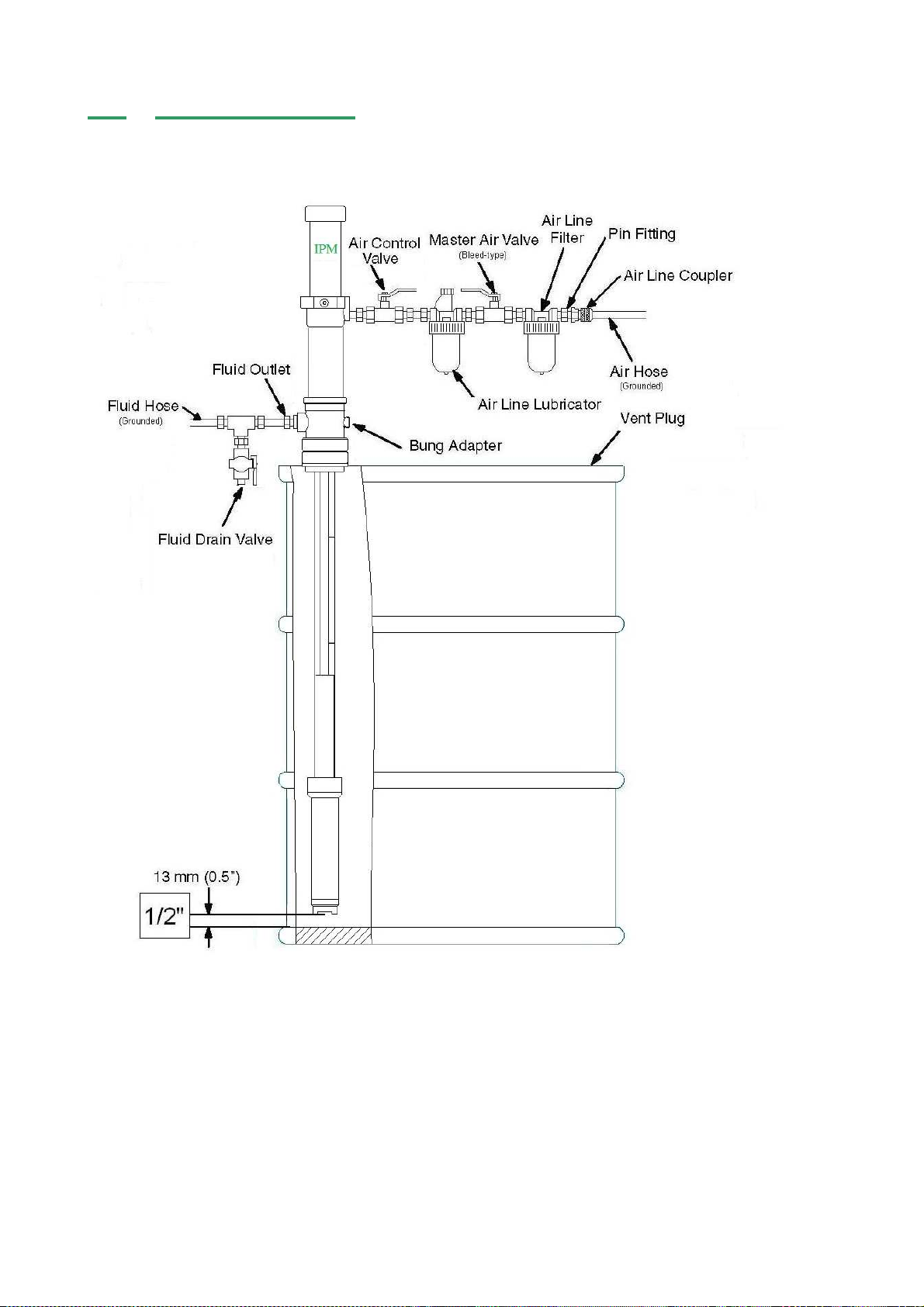
2. Use the air bleed down valve (see INSTALLATION, page 8) to relieve the air
pressure in the system.
3. Relieve the fluid pressure by holding a grounded metal pail in contact with the metal
part of the fluid dispense valve and slowly opening the valve.
4. With a container ready to catch the fluid, open the drain valve (see INSTALLATION,
page 8).
5. It is a good practice to leave the drain valve open until it is time to dispense fluid
again.
If you are unsure that the fluid pressure has been relieved due to a blockage in a
component or a hose, carefully relieve the pressure by carefully loosening the hose end
coupling to allow the fluid pressure to escape slowly. After the pressure has been relieved,
the fitting can then be removed and any blockages removed.
Flush the pump before initiating operation
1. The pump is tested with lightweight DOP oil, which is left in to protect the pump
parts. If the fluid you are pumping may become contaminated by oil, flush oil from
pump with a compatible solvent before use. Follow the flushing instructions below.
2. When pumping fluids that set up or solidify, flush the system with a compatible
solvent as often as necessary to remove build-up of solidified chemicals in the
pump or hoses.

6
3. If the pump is being used to supply a circulating system, allow the solvent to
circulate through the entire system for at least 30 minutes every 48 hours or more
often if necessary to prevent settling and solidification of chemicals.
4. Lubricate the throat packing frequently, when you are pumping a non-lubricating
fluid or shutting down for more than one day
Shut down & care of pump
For Overnight shut down, follow the Pressure Relief Procedure. Always stop the pump
at bottom of the stroke to prevent the fluid from drying on the exposed displacement rod
and damaging the throat packing.
Hazards from fire or explosion
Hazards exist where sparks can ignite vapors or fumes from combustible chemicals or
other hazardous conditions exist such as explosive dust, etc. These sparks can be created
from plugging in or unplugging an electrical supply cord or from the static electricity
generated by the flow of fluid through the pump and hose.
Every part of the equipment must be properly grounded to prevent static electricity from
generating a spark and causing the pump or system to become hazardous. These sparks
can cause a fire, explosion, property and equipment damage and serious bodily injury.
Ensure that the pump and all components and accessories are properly grounded and that
electrical supply cords are not plugged in or unplugged when these hazards exist.
Should any evidence of static electricity (sparks or small shocks while in contact with the
equipment) exist, discontinue pump operation immediately. Investigate the source of the
static electricity and correct the grounding problem. Do not use the system until the
grounding problem is repaired.
Pump and component grounding procedures
Always use the following procedures for grounding the pump. Loosen the lock screw to
allow insertion of one end of a minimum sized 12 gauge wire into the bore hole of the
grounding lug. Insert 12 gauge wire and tighten the lock screw securely. The other end of
the ground wire must be secured to a true earth ground.

7
1. Air compressor: Follow the grounding procedures as recommended
by the compressor manufacturer.
2. Air hoses: Always use grounded air hoses.
3. Fluid container used to Grounding must be done according to local electrical
supply the system: codes.
4. Pump: Follow the procedures referred to in FigureA (page 6).
5. Fluid Hoses: Always use grounded fluid hoses.
6. Dispensing Valve: The valve must be metal to conduct through the fluid
hose to the pump which must be properly grounded.
7. Dispensing Point: Grounding must be done according to local electrical
codes.
8. Solvent Containers Grounding must be done according to local electrical
codes. use only metal: conductive pails that are properly grounded.
9. Grounding while Maintain conductivity by firmly securing the metal part
dispensing, cleaning of the dispensing valve to the side of a grounded metal
or relieving pressure: container.
Hose grounding
It is very important that the hoses used for both air and fluid dispensing be a grounding
type and that ground continuity is maintained at all times during operation. Regular checks
of the hose ground resistance (with a resistance meter using a suitable range) and a
comparison to the manufacturer’s specifications will ensure that the ground is within
specifications. If it is not within specified limits it should be replaced immediately.
Solvent cleaning
While cleaning the system with solvent, secure the metal part of the dispensing valve in
contact with a grounded metal pail to minimize the possibility of splashing/spraying of
chemicals on the skin, in the eyes and around static sparks. Use low fluid pressure for
additional safety.
Hazards from moving parts
Use the Pressure Relief Procedure (page 5) to prevent the pump from starting un-
intentionally or unexpectedly. Be aware of moving parts that present a pinching hazard to
fingers or other body parts. Stay clear of these moving parts at all times when starting or
operating the pump.
Safety standards
Safety standards have been established by the United States Government under the
Occupational Safety and Health Act. These standards should be consulted as they apply to
the hazards and type of equipment being used.

8
2.0 INSTALLATION
Figure B depicts only a typical installation providing a guide for your reference but many
other installation methods can be used based on your specific application. Some parts
shown are not included but are sold separately. Feel free to call your Local Distributor
for assistance.

9
2.1 Installation procedures
Install the necessary accessories in sequence using Figure B (page 8) as a guide. An air
control valve (IPM part #601805) for controlling air flow is required. To minimize the risk of
serious injury such as splashing/spraying chemicals on the skin, in the eyes or injury from
moving parts, install the following accessories in your system.
1. Bleed-off master air valve
This valve will relieve the air trapped in the system after pump operation is ceased.
Air that is trapped between this valve and the pump can cause the pump to
reciprocate
un-intentionally or un-expectantly and may cause injury to the operator.
2.
Fluid Drain Valve
The fluid drain valve is installed to relieve fluid pressure in the pump, hose or at the
dispensing valve when pump operation is ceased. The relief of pressure by the
dispensing valve, which at times is inadequate if there is a clog or other restriction
in the hose or dispensing valve can be achieved by using this fluid drain valve.
Always use a metal valve for grounding purposes.
Lubrication
Connect an air lubricator to help achieve maximum pump longevity. The in-line lubricator
provides proper lubrication to the air motor during operation. Next, install a bleed-off
master air valve on the system. This valve is required on your system to relieve trapped air
as explained above.
Air filters help to remove dirt and foreign particles from the supply air. Water moisture will
also be trapped within this filter. Be sure to release the trapped water daily as a good
maintenance practice. Connect a grounded air supply hose for main air supply.
For the fluid section, connect one fluid drain valve directly after the outlet of the pump. Be
sure to connect it pointing downwards for safety. Connect a grounded fluid hose to the fluid
outlet 3/4” NPT (female).
Ensure that installation is fully completed before proceeding with start up
operations.
Ensure grounding of the pump and accessories is completed before beginning
pump operation. Observe all OSHA and other safety regulations.

10
3.0 OPERATION
3.1 Start up and adjustment of transfer pump
1. Ensure that the air control valve is closed then open the bleed-type master air valve.
Connect the quick disconnect coupler to the male fitting.
2. For safety, open the dispensing valve slowly, then drain fluid into a grounded metal
container. Ensure metal-to-metal contact is maintained between the container and
the valve at all times.
3. Adjust the air control valve slowly for just enough pressure to start running the
pump. This is to prime all air within the system. After all the air has been expelled
from the lines, close the dispensing valve. During the priming of the pump, the
pump operates when the dispensing valve is opened and stops when the valve is
closed.
4. Turn the air regulator slowly until sufficient flow from the dispensing valve is
achieved. Remember to always run the pump at the lowest possible speed
necessary to achieve what is desired. Never exceed the maximum working
pressure of any component in the system.
5. The pump should not be left to run dry of the fluid being worked upon. When
running empty, the operating speed will rise rapidly, increasing the chance of
damage to the pump and/or components. During operation should the pump be
found to run too fast, stop it immediately and ensure the fluid supply is not too low
or the drum is empty. If air has gone into the system, repeat the priming procedure.
Ensure that all air has been expelled from the lines before beginning operation
again. Flush the pump or leave it filled with a compatible solvent when not in use.
6. Always follow the Pressure Relief Procedure should the pump be put away for any
period of time or during system shut off at the end of the day.
3.2 Shut down procedure
1. Relieve the air pressure with the air regulator.
2. Open the air needle valve.
3. Bleed off residual pressure in the system with the bleed-off master air valve.
4. Open the drain valve to relieve fluid pressure in the system. Use a container to
collect the fluid drained off. Be especially careful as the fluid may still be under
pressure. Hold the metal fluid drain valve against the side of the grounded
container while relieving the pressure.
Note: For long periods of shut-down, flush the pump thoroughly with an
appropriate cleaning fluid to prevent solidified chemical build-up.

11
4.0 MAINTENANCE AND REPAIR
4.1 Air motor section disassembly
1. Follow the Procedure for Pressure Relief (page 5). It is very important to
relieve all air and fluid line pressure as well as pump pressure before
proceeding to the next step or injury can occur.
2. Remove inlet and outlet hoses. Place the pump in a vise or other holding
device. If you know that you just need to work on the air motor, the pump can
simply be left in the drum it is operating in.
3. Clamp on the housing with the outlet hole against one of the jaws of the
vice. When clamping the housing- either the air motor assembly or the
lower tube and/or foot valve can be removed.
Use a strap wrench to remove the air motor assembly.
The pump assembly can be removed from the air motor by disengaging the Piston Rod.

12
Remove the air cylinder either by hand or by using a strap wrench.
Air motor assembly and piston rod with the air cylinder removed.
Place a pair of channel-lock pliers on the knurled area of the exhaust valve plate and a
crescent wrench on the flats to remove the air piston assembly. Examine the spring in the
air motor cap to ensure that it is not damaged or loose. Examine the gasket in the air
motor cap and replace as needed. This gasket seals the cylinder cap to the air cylinder.
Also inspect the lower return spring to ensure it is secured correctly into the air motor base
assembly.

13
4.2 Air motor section assembly
Assemble the air motor assembly in reverse order from above procedure. Ensure all
parts shown in illustration below are included and in operable shape. The air exhaust
valve plate and socket head screws require the use of threadlocker on the threads to
ensure they do not vibrate loose. It is also important to check the rubber stop in the
air exhaust valve plate to ensure it is secure. Tighten the screws to 10-14 inch
pounds.
1. Assemble the air piston assembly (use thread sealant), with washer onto piston rod.
Hand-tighten only.
2. Place O-ring inside the machined groove in the air motor base. Place gasket in the top
of the air motor base with spring centered inside the gasket, resting on the air motor
base. Slide the piston rod and air valve assembly in to the air motor base.

14
3. Insert the conical spring into the machined groove in the air cylinder cap followed by
the square cut gasket. Clamp the air motor base into a vice, using a strap wrench to
re-assemble the air cylinder and air cylinder cap to the air motor base. Hand-tighten
only the air cylinder cap so as not to damage the gasket.
4. Place the connecting ring around the connecting rod housing and hand-tighten.
4.3 Fluid section disassembly
1. Remove the foot valve while holding the cylinder with a strap wrench.
2. With the upper air motor assembly already removed, you should be able to simply
push from the upper ball end the complete assembly out the bottom of the lower
section.
3. Use two wrenches and dismantle the upper pump section. Note the orientation of the
Teflon cups. One faces up, followed by a wear ring in the center and the second cup
faces down followed by a lower support washer. Use threadlocker when re-installing.
Breakdown of upper portion of the lower connecting rod assembly.

15
Internal foot valve disassembled. Clean, inspect or replace if necessary these
components before re-assembly. Use threadlocker when re-installing.
After the lower piston rod is inspected and proper parts replaced/cleaned as needed,
inspect the lower body assembly and make sure that they are also clean and free
from any scratches. Grease and push this assembly back up from the bottom into
the pump’s cylinder just far enough to re-attach the foot valve.
Lower foot valve parts. On the stubby version of the IP02 pump there are ¾”
female pipe threads under the foot valve- on the drum length there are not. Should
you need to extend into your container farther it is recommended to install a cylinder
extension tube to keep the foot valve at the lowest possible point.
Be sure to inspect, clean and replace any of the above items if needed. You will
need to re-assemble the foot valve assembly in reverse from the way that you
removed it.
Breakdown of internal foot valve.

16
4.4 Securing the fluid section to the air motor section
The piston rod is actually inside the air motor assembly- which has been removed in the
above illustration so you can see more detail.
Notice how the upper connecting rod is being inserted at an angle. This is to ensure that
the ball on the end correctly engages the keyway slot in the photo on the left.
You will need to “hook” the ball in to the slot by moving the rod at an angle, then press it
towards the center of the notch.
Note: the lower section will need to have the piston rod extended and the air motor
will need to be in the down position in order for you to have enough length to hook
these two components together.
Connect the air motor section to the outlet housing as shown above.
You should now be ready to re-install the pump into your container. Attach the fluid hose
first and tighten before attaching the air line and turning the air supply back on.

17
5.0 PARTS IDENTIFICATION
5.1 Parts drawing for air motor section
Pump # 810201、
、、
、810203
*Part number 500142 (threads) and part number 500138 require the Loctite 243
to help ensure they do not come undone.
**Part number 700027 (threads) require the use the Loctite 243 to help ensure
they do not come undone.

18
5.2 Parts drawing for fluid section
Pump # 810201

19
5.3 Parts drawing for fluid section
Pump # 810203

20
5.4 Parts drawing for air motor section
Pump # 810202、
、、
、810204
*Part number 500142 (threads) and part number 500138 require the Loctite 243
to help ensure they do not come undone.
**Part number 700027 (threads) require the use the Loctite 243 to help ensure
they do not come undone.
Other manuals for IP02 Series
5
Table of contents
Other IPM Water Pump manuals
Popular Water Pump manuals by other brands

Grundfos
Grundfos CMV Series Installation and operating instructions

GORMAN-RUPP
GORMAN-RUPP S Series Installation and operation

Ingersoll-Rand
Ingersoll-Rand ARO 66625 C Series Operator's manual

Sandpiper
Sandpiper S15 Non-Metallic Service & operating manual

Armstrong
Armstrong FUSED DISCONNECTS Installation and operating instructions

Debem
Debem CUBIC Series Instructions for use and maintenance