Harbinger HA80 User manual

HA80 User Manual
4 Channel PA System
www.harbingerproaudio.com

HA80
Congratulations on your purchase of the Harbinger HA80 PA Mixer and Speaker System. Built within rugged, vinyl-covered wood
enclosures, they are the ideal choice for musicians looking for a PA that sounds great, night after night.
This manual will help you setup your new system. By following our guidelines and suggestions, your new Harbinger will provide many
years of great sound and reliable service.
Inside you’ll find:
• 80 Watt Mixer/Amplier
• Two Full-range Two-way Speakers for Rich Sound
• 4 Channels with Individual Balanced Mic/Unbalanced Line Inputs
• Built-in Digital Delay Effect & 3-Band Master EQ
• Volume, Tone, and Effect Levels on Every Channel for Complete Sound Control
• AUX Input for CD and MP3 Players
• Stereo Output to Recorders, Tape Decks, Computers and more
• Exclusive “Sure-Protect” Rubber Corners on Mixer and Speakers for Long-Lasting Protection
• Built-in Stand Mounts will t Standard Mounting Poles
• Two 25’ Speaker Cables included
1
Welcome
FCC Statements
1. Caution: Changes or modifications to this unit not expressly approved by the party responsible for compliance could void the user’s
authority to operate the equipment.
2. Note: This equipment has been tested and found to comply with the limits for a Class B digital device, pursuant to Part 15 of the FCC
Rules. These limits are designed to provide reasonable protection against harmful interference in a residential installation. This equip-
ment generates, uses, and can radiate radio frequency energy and, if not installed and used in accordance with the instructions, may
cause harmful interference to radio communications. However, there is no guarantee that interference will not occur in a particular
installation. If this equipment does cause harmful interference to radio or television reception, which can be determined by turning
the equipment off and on, the user is encouraged to try to correct the interference by one or more of the following measures:
• Reorient or relocate the receiving antenna.
• Increase the separation between the equipment and receiver.
• Connect the equipment into an outlet on a circuit different from that to which the receiver is connected.
• Consult the dealer or an experienced radio/TV technician for help.
User Manual
2
Important Safety Instructions
DANGER
Exposure to extremely high noise levels may cause
permanent hearing loss. Individuals vary considerably
to noise-induced hearing loss but most will lose some
hearing if exposed to intense noise for a sufficient
period of time.
The U.S. Government’s Occupational Safety and Health
Administration (OSHA) has specied the following
permissible noise level exposures:
According to OSHA, any exposure in the above permissible
limits could result in some hearing loss. Ear plugs or
protectors in the ear canal or over the ears must be worn
when operating this amplification system in order to prevent
a permanent hearing loss. If exposure in excess of the limits
as put forth above, to insure against potentially harmful
exposure to high sound pressure levels, it is recommended
that all persons exposed to equipment capable of inducing
high sound pressure levels, such as this amplification
system, be protected by hearing protectors while this unit is
in operation.
THIS SYMBOL IS INTENDED TO ALERT THE USER TO THE PRESENCE
OF NON-INSULATED “DANGEROUS VOLTAGE” WITHIN THE
PRODUCT’S ENCLOSURE THAT MAY BE OF SUFFICIENT MAGNITUDE
TO CONSTITUTE A RISK OF ELECTRIC SHOCK TO PERSONS.
THIS SYMBOL IS INTENDED TO ALERT THE USER TO THE PRESENCE
OF IMPORTANT OPERATING AND MAINTENANCE (SERVICING)
INSTRUCTIONS IN THE LITERATURE ACCOMPANYING THE UNIT.
APPARATUS SHALL NOT BE EXPOSED TO DRIPPING OR SPLASHING
AND THAT NO OBJECTS FILLED WITH LIQUIDS, SUCH AS VASES,
SHALL BE PLACED ON THE APPARATUS.
IMPORTANT SAFETY INSTRUCTIONS
1. Read all safety and operating instructions before using
this product.
2. All safety and operating instructions should be kept for
future reference.
3. Read and understand all warnings listed on the
operating instructions.
4. Follow all operating instructions to operate this product.
5. This product should not be used near water, i.e. a bathtub,
sink, swimming pool, wet basement, etc.
6. Use only a dry cloth to clean this product.
7. Do not block any ventilation openings. The product should
not be placed flat against a wall or placed in a built-in
enclosure that will impede the flow of cooling air.
8. Do not install this product near any heat sources, such
as radiators, heat registers, stoves or any other apparatus
(including heat producing ampliers) that produces heat.
9. Do not defeat the safety purpose of the polarized or
grounding-type plug. A polarized plug has two blades with
one wider than the other. A grounding-type plug has two
blades and a third grounding prong. The wide blade or the
third prong are provided for your safety. If the provided
plug does not fit into your outlet, consult an electrician for
replacement of the obsolete outlet.
10. Protect the power cord being walked on or pinched,
particularly at plugs, convenience receptacles and the
point where they exit from the apparatus. Do not break the
ground pin of the power supply cord.
11. Only use attachments specied by the manufacturer.
12. Use only with the cart, stand, tripod, bracket,
or table specified by the manufacturer or
sold with the apparatus. When a cart is
used, use caution when moving cart/
apparatus combination to avoid injury
from tip-over.
13. Unplug this apparatus during lightning storms or when
unused for long periods of time.
14. Care should be taken so that objects do not fall and liquids
are not spilled into the unit through the ventilation ports or
any other openings.
15. Refer all servicing to a qualied service professional.
Servicing is required when the apparatus does not oper-
ate normally or has been damaged in any way, including
damage to the power cord or plug, damage due to liquids
spilled or objects dropped inside the unit, dropping the
unit, or anything else that interrupts normal use of the unit.
16. WARNING: To reduce the risk of re or electric shock, do
not expose this apparatus to rain or moisture.
17. When a mains plug is used as the disconnect device, the
disconnect device shall remain readily operable.
DURATION PER DAY (HOURS) 8 6 4 3 2 1
SOUND LEVEL (dB) 90 93 95 97 100 103

HA80
1. Volume Control - This controls the volume for each channel and sends the signal to the master mix bus. Typical operation
is between 4 and 8, depending upon the device(s) on the channel. Please remember that this acts like a preamp, so if you are
using a device that has a volume output control (i.e. an MP3 player or CD player) you will need to do some level matching by
adjusting the level controls on each unit.
2. Tone Control - This adjusts the overall tone for the output of the channel. It is set at 5 kHz. Since it is a cut or boost control
(+/- 15 dB), it will add or diminish the presence of the sound’s content around that frequency.
3. Effect Control - This is a send control to the Effect, sending the signal from each channel to the delay effect. The output
of the delay is blended back in with the mixer’s overall output using the master effect knob (7).
4. 3 Pin Low Impedance Microphone Input - Phantom power (1.5 volts) for condenser microphones is consistently available.
Input has an impedance of 1k Ohm. The connector is wired as: Pin 1 = shield; Pin 2 = positive (hot); Pin 3 = negative (cold)
5. 1/4” Line/High Impedance Input - This input can be used as an input for either a high-impedance microphone or line level
device, like a guitar, keyboard or sampler. It is a 2-conductor input with an impedance of 10k Ohms. Both the high and low
impedance inputs may be used simultaneously.
6. Master Volume - This controls the overall volume level of the entire amplifier. Typical operation is between 4 and 8.
7. Master Effect - This controls the level of delay effect added back to the overall mix.
8. Aux Volume - This controls the level coming in from the Aux In RCA plugs on the unit’s back panel.
9. Master Low - This controls the overall amount of bass frequencies (100 Hz), allowing +/- 15 dB of boost or cut.
10. Master Mid - This controls the overall amount of middle frequencies (1.5kHz), allowing +/- 15 dB of boost or cut.
11. Master High - This controls the overall amount of high frequencies (10kHz), allowing +/- 15 dB of boost or cut.
12. Power - This switches the unit on or off. When the unit is powered up, a red LED will illuminate.
Front Panel
123
4 5
678
910 11 12
3
User Manual
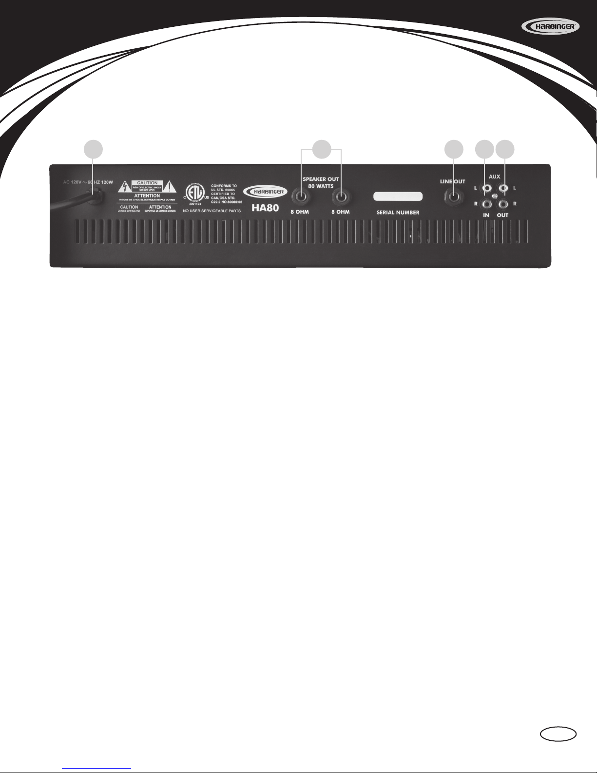
1. AC Cable - Standard cable for use with standard voltages from AC wall outlets. It is grounded and should never have the
ground pin removed for any reason.
2. Speaker Out - 1/4”, 2-conductor speaker outputs. Each one is rated for an 8 Ohm minimum impedance. Total minimum load
for the amplier is 4 Ohms. You may connect one 4 Ohm, one 8 Ohm, or two 8 Ohm speaker cabinets. Do not go below the rated
minimum impedance.
3. Line Out - 1/4”, 2-conductor line level output. The impedance is 1k Ohm @ -10 dBv. It is used to connect the HA80 to either
an additional power amplier or an external recording device. This line level signal comes out after the master EQ section and
before the power amp.
4. Aux In - RCA jacks for playing an MP3 Player, CD player or other line level source through the system. The impedance is 10k
Ohms @ -10 dBv. Aux volume on front panel (8) controls the level of this input. Stereo input is summed internally for mono playback
through the system.
5. Aux Out - RCA jacks for hooking up a stereo recording device to record directly from the mixer. The signal is taken from the
pre-master section, so it does not include the master tone section, the delay effect, or the Aux In signal. The impedance is
1k Ohm @ -10 dBv.
1
Back Panel
2 3 4 5
4

HA80
Model HA80 4 Channel Powered Mixer
Power Output 80 Watts 4 Ohms
55 Watts 8 Ohms
Inputs
CH 1 - 4 Mic XLR Balanced. Line 1/4” Unbalanced
Mono
AUX IN
Line Level RCA Stereo IN, summed
internally for mono playback through
system.
Maximum Gain (Volume Max.,
Tones at)
+70 dB Mic Input (Ch 1 - 4) to Speaker Out
+50 dB Line input (CH 1 - 4) to Speaker Out
+40 dB Tape In to Speaker Out
+40 dB Mic Input (Ch 1 - 4) to Line Out
+20 dB Line input (CH 1 - 4) to Line Out
+10 dB Tape In to Line Out
+40 dB Mic Input (Ch 1 - 4) to Tape Out
+20 dB Line input (CH 1 - 4) to Tape Out
Input Channel Equalization ± 15 dB @ 5 kHz Tone
Master Equalization
± 15 dB @ 10 kHz High
± 15 dB @ 1.5 kHz Mid
± 15 dB @ 100 Hz Low
Phantom Power +15v Mic XLR Balanced inputs (Ch 1 - 4)
Power Requirements
USA/Canada 120VAC/60Hz, 120 Watts nominal
Europe 230VAC/50Hz, 120 Watts nominal
UK 230VAC/50Hz, 120 Watts nominal
Australia 240VAC/50Hz, 120 Watts nominal
Dimensions & Weight (Powered
Mixer only)
mm/kg 130 (Height) x 480 (Width) x 310 (Depth),
8.1 kg
Inches/Pounds 5.1 (Height) x 18.9 (Width) x 12.2 (Depth),
17.9 lbs
Speaker Information
Power Capacity 60 Watts each RMS
120 Watts each Program Power (peak music power)
Frequency Response 75Hz - 18kHz
Sensitivity 96 dB each 1 Watt - 1 Meter
Nominal Impedance 8 Ohms
Dimensions & Weight Per Cabinet
mm/kg 475 (Height) x 350 (Width) x 270 (Depth),
9.8 kg
Inches/Pounds 18.7 (Height) x 13.8 (Width) x 10.6
(Depth), 21.6 lbs
Specifications
5
User Manual
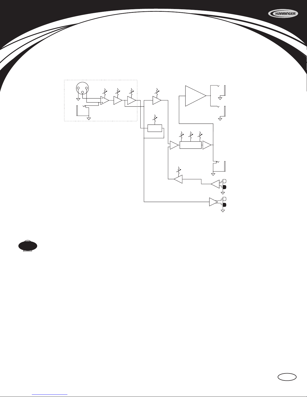
CH 1 - 4
MIC
LINE
1
2
3
Volume Tone Effect
Master
Volume
Effect
Volume
Effect
Effect Bus
Main Bus
In Out
Power Amp
Speake
r
Out
Speake
r
Out
Low Mid High
Master EQ
In Out
Sum
Aux
Volume Line
Out
Aux
In
Aux
Out
Sum
Harbinger Limited Warranty
Harbinger provides to the original purchaser a two (2) year limited warranty on materials and workmanship on all Harbinger cabinets and loudspeaker components from the
date of purchase.
If your covered product is defective, ship the defective component together with proof of purchase, freight prepaid and insured, to an Authorized Harbinger repair center or directly to Harbinger
Support Headquarters. If you are uncertain which component is defective, or to obtain instructions for removing a component, please contact Harbinger Support Headquarters for assistance at
support@HarbingerProAudio.com, or visit www.HarbingerProAudio.com.
A Return Authorization Number must be obtained from our Customer Service Department prior to shipping the product. To locate a repair center near you and to obtain a Return Authorization
Number, contact [email protected] or visit www.HarbingerProAudio.com.
This warranty does not cover service or parts to repair damage caused by neglect, abuse, normal wear and tear and cosmetic appearance to the cabinetry not directly attributed to defects in
materials or workmanship. Also excluded from coverage are damages caused directly or indirectly due to any service, repair(s), or modications of the cabinet, which has not been authorized
or approved by Harbinger. This two (2) year warranty does not cover service or parts to repair damage caused by accident, disaster, misuse, abuse, burnt voice-coils, over-powering, negligence,
inadequate packing or inadequate shipping procedures. The sole and exclusive remedy of the foregoing limited warranty shall be limited to the repair or replacement of any defective or non-
conforming component. All warranties including, but not limited to, the express warranty and the implied warranties of merchantability and fitness for a particular purpose are limited to the two
(2) year warranty period. Some states do not allow limitation on how long an implied warranty lasts, so the above limitation may not apply to you. There are no express warranties beyond those
stated here. In the event that applicable law does not allow the limitation of the duration of the implied warranties to the warranty period, then the duration of the implied warranties shall be
limited to as long as is provided by applicable law. No warranties apply after that period.
So we may serve you better, please register on-line at www.HarbingerProAudio.com
California Prop 65 Warning
This product may contain a chemical(s) known to the state of California to cause cancer or birth defects or other reproductive harm.
Retailer and manufacturer shall not be liable for damages based upon inconvenience, loss of use of product, loss of time, interrupted operation or commercial loss or any other incidental or con-
sequential damages including but not limited to lost profits, downtime, goodwill, damage to or replacement of equipment and property, and any costs of recovering, reprogramming, or reproduc-
ing any program or data stored in equipment that is used with Harbinger products. This guarantee gives you specic legal rights. You may have other legal rights, which vary from state to state.
Harbinger, P.O. Box 5111, Thousand Oaks, CA 91359-5111
All trademarks and registered trademarks mentioned herein are recognized as the property of their respective holders.
Made in China 0807-8187.01
HA80 Block Diagram & Warranty
2
6

www.harbingerproaudio.com
Table of contents
Other Harbinger Speakers manuals

Harbinger
Harbinger MUV SERIES User manual

Harbinger
Harbinger HP112 User manual

Harbinger
Harbinger V2300 Series User manual

Harbinger
Harbinger HA60 User manual

Harbinger
Harbinger V1012 User manual

Harbinger
Harbinger V2212 User manual

Harbinger
Harbinger MLS800 User manual

Harbinger
Harbinger MUV SERIES User manual

Harbinger
Harbinger VaRi V2115 User manual

Harbinger
Harbinger APS12 User manual


