Hardi Commander Twin Force Plus User manual

1
GB 01 06
Illustrations, technical information and data in this book are to the best of our belief correct at the time of printing. As
it is HARDI INTERNATI NAL A/S policy permanently to improve our products, we reserve the right to make
changes in design, features, accessories, specifications and maintenance instructions at any time and without
notice. HARDI INTERNATI NAL A/S is without any obligation in relation to implements purchased before or after
such changes.
HARDI INTERNATI NAL A/S cannot undertake any responsibility for possible omissions or inaccuracies in this
publication, although everything possible has been done to make it complete and correct.
As this instruction book covers more models and features or equipment, which are available in certain countries
only, please pay attention to paragraphs dealing with precisely your model.
Published and printed by HARDI INTERNATI NAL A/S
We congratulate you for choosing a HARDI plant protection product. The reliability and
efficiency of this product depend upon your care. The first step is to carefully read and
pay attention to this instruction book. It contains essential information for the efficient
use and long life of this quality product.
As the instruction book covers all OMMANDER plus models with HAY boom or HAZ
boom, please pay attention to the paragraphs dealing with precisely your model.
This book is to be read in conjunction with the Spray Technique book.
More information about the OMMANDER plus can be found on the products own web-
site at: http//www.commander-plus.com
COMMANDER
TWIN FORCE
Instruction book
670747-GB-2000/01

2

3
TT
TT
Taa
aa
abb
bb
ble ofle of
le ofle of
le of Contents Contents
Contents Contents
Contents
Declaration of Conformity ........................................................ 4
Operator safety ........................................................................ 5
COMMANDER plus .................................................................. 6
Sprayer use ............................................................................. 8
Unloa ing the sprayer from the truck ....................................... 8
Before putting the sprayer into operation ................................. 8
Connecting the sprayer ............................................................ 9
Drawbars ..................................................................... 9
Fixe rawbar ...............................................................10
STEERING rawbar ..................................................... 10
SELF TRACK for COMMANDER 2200/2800 ................ 10
TRAIL CONTROL ......................................................... 10
Transmission shaft ................................................................... 11
Operator safety ............................................................ 11
Installation of transmission shaft ...................................11
Track gauge ............................................................................. 13
Altering the track gauge ................................................13
A justment ranges - track wi th ....................................14
Permitte rim positions ................................................. 15
Hy raulic systems .................................................................... 16
Tractor Operate Hy raulics ......................................... 16
Direct Acting Hy raulic system ..................................... 16
Loa Sensing ............................................................... 16
Control boxes an power supply ............................................... 17
Brakes ......................................................................................18
Emergency an parking brake (if fitte ) ........................ 18
Hy raulic activate brakes (if fitte ) .............................. 18
Air activate brakes (if fitte ) ........................................ 18
Single-line brakes (if fitte ) ........................................... 19
Dual-line brakes (if fitte ) .............................................. 19
Counter weight (TRACKER mo els only) ................................. 20
Transport ................................................................................. 21
Roa worthiness ........................................................... 21
Rear lights (if fitte ) ...................................................... 21
Transport brackets, height setting ................................ 21
Transport lock .............................................................. 22
Driving Technique ..................................................................... 23
STEER TRACK an SELF TRACK ............................. 23
STEER TRACK ........................................................... 23
SELF TRACK .............................................................. 24
TRAIL CONTROL ........................................................ 24
Equipment - Stan ar an A itional ....................................... 25
La er ......................................................................... 25
Platform ....................................................................... 25
Tank level in icator ...................................................... 25
Large storage Locker (if fitte ) ..................................... 25
Small storage Locker (if fitte ) ..................................... 25
Front Locker (if fitte ) .................................................. 25
Boom an Work lights (if fitte ) ................................... 26
Crop protection Kit (if fitte ) ........................................ 27
Mu guar s (if fitte ) .................................................... 28
Disconnecting the sprayer ....................................................... 29
Operating the boom ................................................................. 30
The HAY boom ............................................................. 30
The HAZ boom ............................................................. 30
Air slot angling ............................................................. 30
Electrical fan spee a justment (if fitte ) ...................... 31
Boom suspension sensitivity ........................................ 31
Operating the liqui system ...................................................... 32
MANIFOLD SYSTEM ............................................................... 32
Use of MANIFOLD valve system ................................. 32
Electrical operate MANIFOLD valves (if fitte ) ............ 33
Quick reference ............................................................ 33
Filling of water .............................................................. 33
Filling of rinsing tank (if fitte ) ....................................... 35
Filling of clean water tank ............................................. 36
A justment of EVC operating unit ................................ 36
A justment of pressure equalisation ............................. 36
Operating the control unit while spraying ...................... 37
Remote pressure gauge (if fitte ) ................................. 37
Filters ....................................................................................... 37
Self-cleaning filter .........................................................37
Choice of correct restrictor ........................................... 37
Filling of chemicals ................................................................... 38
Filling of Liqui chemicals .............................................38
Filling of Pow er chemicals .......................................... 39
Use of rinsing tank an rinsing nozzles (if fitte ) ..................... 40
Technical Resi ue .................................................................... 41
Draining a resi ue ........................................................ 41
Using the rain valve ................................................................ 41
Using the suction quick coupler ................................................ 41
Operation of the rain valves .................................................... 41
Safety precautions ................................................................... 42
Personal protection .......................................................42
Air technique ............................................................................ 43
Air spee / Air volume ...................................................43
Blower a justment ........................................................ 43
Angling of air an liqui ................................................ 43
A justing the air assistance .......................................... 43
Setting of air spee , rules of thumb .............................. 44
Angling of air an liqui , rules of thumb ........................ 44
Water sensitive paper ................................................... 45
Maintenance - rules of thumb ................................................... 49
Cleaning the sprayer ................................................................ 49
Cleaning the tank ......................................................... 49
Cleaning an maintenance of filters ..............................50
Lubrication ............................................................................... 51
Lubricating points ......................................................... 51
Service an Maintenance intervals ........................................... 56
10 hours service ........................................................... 56
50 hours service ........................................................... 56
100 hours service ......................................................... 56
250 hours service ......................................................... 56
500 hours service ......................................................... 56
1000 hours service or yearly, whichever comes first ..... 57
Occasional maintenance .............................................. 57
Off-season storage ................................................................... 76
Off-season storage program ......................................... 76
Preparing the sprayer for use after storage ................... 76
Fault-fin ing ............................................................................. 77
Operational problems ............................................................... 77
TRACKER amping system ......................................... 77
Liqui system ............................................................... 78
EVC Operating unit ...................................................... 79
Hy raulic system (Tractor Operate Hy raulics) ........... 79
Hy raulic system (Direct Acting Hy raulic System) ....... 80
Hy raulic fan transmission ........................................... 81
Emergency operation of the sprayer ......................................... 82
The boom ..................................................................... 82
Steering rawbar (if fitte ) ............................................ 82
Technical specifications ............................................................ 83
Overall imensions ....................................................... 83
Weight ..........................................................................83
Pump capacity ............................................................. 85
Filters an nozzles ....................................................... 86
Temperature an pressure ranges................................. 86
Brakes ..........................................................................86
Materials an recycling ................................................ 86
Disposal of the sprayer ................................................ 86
Conversion factors, SI to Imperial units ........................ 86
Electrical connections 86
Rear lights .................................................................... 86
Electrical connections for EVC operating unit ............... 87
Electrical chart (EVC) .................................................. 87
Installation instruction for boom an work light ............. 88
Electrical specifications for Boom an Work light ......... 89
Boom hy raulic charts .............................................................. 90
Subject in ex ............................................................................xx

4 GB 02 01
EC Declaration
Dec Dec
Dec Dec
Declarlar
larlar
laraa
aa
ation oftion of
tion oftion of
tion of Conf Conf
Conf Conf
Conformityormity
ormityormity
ormity
Manufacturer, Importer,
HARDI INTERNATI NAL A/S
Helgeshøj Allé 38
DK 2630 Taastrup
DENMARK
declare that the following product;
_________________________________________________________________________________________
A. was manufactured in conformity with the provisions in the C UNCIL DIRECTIVE of 14 June 1989 on mutual
approximation of the laws of the Member States on the safety of machines (89/392/EEC as amended by directives
91/368/EEC and 93/368/EEC) with special reference to Annex 1 of the Directive on essential safety and health
requirements in relation to the construction and manufacture of machines.
B. was manufactured in conformity with the current standards implementing harmonised standards in accordance
with Article 5 (2) and other relevant standards.
Taastrup, January 2000
_____________________________________________
Erik Holst
Managing Director
HARDI INTERNATI NAL A/S
Adhere extra shipping package labels in the Product Identification Certificate.

5 GB 03 01
Safety notes
OperOper
OperOper
Operaa
aa
ator saftor saf
tor saftor saf
tor safetyety
etyety
ety
Watch for this symbol .
It means WARNING, CAUTI N,
N TE. Your safety is involved so be
alert!
Note the following recommended precautions and safe
operating practices.
Read and understand this instruction book
before using the equipment. It is equally
important that other operators of this equip-
ment read and understand this book.
Local law may demand that the operator be
certified to use spray equipment. Adhere to
the law.
Pressure test with clean water prior to filling
with chemicals.
Wear protective clothing.
Rinse and wash equipment after use and
before servicing.
Depressurize equipment after use and before
servicing.
Never service or repair the equipment whilst it
is operating.
Disconnect electrical power before servicing.
Always replace all safety devices or shields
immediately after servicing.
If an arc welder is used on the equipment or
anything connected to the equipment, discon-
nect power leads before welding. Remove all
inflammable or explosive material from the
area.
Do not eat, drink or smoke whilst spraying or
working with contaminated equipment.
Wash and change clothes after spraying.
Wash tools if they have become contaminated.
In case of poisoning, immediately seek medi-
cal advice. Remember to identify chemicals
used.
Keep children away from the equipment.
Do not attempt to enter the tank.
Do not go under any part of the sprayer unless
it is secured. The boom is secure when
placed in the transport brackets.
If any portion of this instruction book remains unclear
after reading it, contact your HARDI dealer for further
explanation before using the equipment.

6GB 04 06
Description
COMMANDER plusCOMMANDER plus
COMMANDER plusCOMMANDER plus
COMMANDER plus
The C MMANDER plus is divided into three zones: a Clean zone, a Working zone and an Application zone, refer-
ring to the level of possible pesticide contamination.
CLEAN ZONE WORKING ZONE APPLICATION ZONE
Please note that some of the features are optional equipment
Locker for protective gear
Clean water tank
Tap for hand washing
Support leg
Pump
P.T. . shaft
Tank level indicator
MANIF LD valves
Couplers for fast filling
Working platform with
ladder
Hydraulic and electric
components
Boom and Work lights
HARDI FILLER
Lockers for pesticide
containers and equip-
ment
PARALIFT boom lift system
Boom
Nozzles
Mudguards
Suspension
Crop Protection Kit
T271-0010x
7
GB 04 06
Description
DescriptionDescription
DescriptionDescription
Description
Frame
Strong and compact frame with several options of
drawbars and wheel sizes. The frame has a strong
chemical and weather resistant electrostatic lacquer
coat. Screws, nuts, etc. have been DELTA-MAGNI
treated to be resistant to corrosion.
Tank
UV-resistant Polyethylene in a suitable design with no
sharp corners for easy agitation, emptying and cleaning.
Nominal contents 2200, 2800, 3200 or 4200 l.
Pump
Diaphragm pump with 6 diaphragms, model 363 or 463,
depending on boom width, with easily accessible valves
and diaphragms. Standard = 540 r.p.m. (6 splines)
ptional = 1000 r.p.m. (21 splines).
MANIFOLD SYSTEM
All functions of the spray circuits are operated via the
centrally situated MANIF LD valves with colour coded
plates and pictorial symbols for easy operation.
Operating unit
The system is based on EVC - Electrical Valve Control.
The on/off is linked to the section valves, which is
resulting in a very quick response to on/off.
The operating unit is constructed of modules and is
electrically controlled via a remote control box.
The built-in HARDI-MATIC ensures a constant volume
per hectare of the liquid (l/ha) at varying forward speed
within the same gear when the number of P.T. . revolu-
tions are between 300-600 r.p.m. (pump 540 r.p.m) or
650-1100 r.p.m. (pump 1000 r.p.m.).
Filters
With the self-cleaning filter the impurities that exist in the
spray liquid will bypass the filter and be recirculated back
to the tank via the return flow. Also suction filter and
nozzle filters are standard. In-line pressure filters can be
fitted as option.
Boom
All booms are suspended in a strong, stable parallelo-
gram boom lift.
The HAY/HAZ booms are trapeze/pendulum suspended
and fully hydraulically operated, including boom slanting
control and air slot angling. HAZ models have Direct
Acting Hydraulics (D.A.H.) and individual boom tilt
function as well.
The TWIN blowers are driven by a built-in hydrostatic
transmission powered via the tractor P.T. . Blower
speed can be adjusted stepwise from the tractor cabin.
The HAY/HAZ booms are available in 18, 20, 21, 24, 27
and 28 m working width.
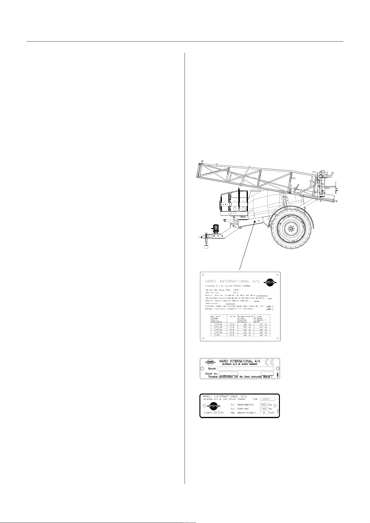
Identifi ation plates
An identification plate fitted on the frame indicates
producer name, model, own weight, max. weight, max.
pressure of the hydraulic system, and max. pressure of
the spray liquid system. Frame, boom centre frame, and
inner/outer sections also have identification plates
indicating boom type and part number of spare parts. If
ordering spare parts, inform your dealer of these, so the
right model and version are described.
T271-0010x
T279-0005
T279-0002
T279-0006
(Certain countries only)

8GB 04 06
Description
SprSpr
SprSpr
Spraa
aa
ayy
yy
yer useer use
er useer use
er use
The HARDI C MMANDER sprayer is for the application
of crop protection chemicals and liquid fertilisers.
The equipment must only be used for this purpose. It is
not allowable to use the sprayer for other purposes.
If no local law demands that the operator must be
certified to use the spray equipment, it is strongly recom-
mended to be trained in correct plant protection and in
safe handling of plant protection chemicals to avoid
unnecessary risk for persons and the environment when
doing the spray job.
Unloading the sprUnloading the spr
Unloading the sprUnloading the spr
Unloading the spraa
aa
ayy
yy
yer frer fr
er frer fr
er from the trom the tr
om the trom the tr
om the trucuc
ucuc
uc
For the unloading of the sprayer a crane or a fork lift is
needed. When loading with a crane please observe the
lifting points as shown on the illustration, and make sure
that the straps or belts used for lifting are strong enough.
BefBef
BefBef
Beforor
oror
ore putting the spre putting the spr
e putting the spre putting the spr
e putting the spraa
aa
ayy
yy
yer intoer into
er intoer into
er into
operoper
operoper
operaa
aa
ationtion
tiontion
tion
Although the sprayer has been applied with a strong and
protective surface treatment on steel parts, bolts etc. in
the factories, it is recommended to apply a film of
anticorrosion oil (e.g. CASTR L RUSTILL or SHELL
ENSIS FLUID) on all metal parts in order to avoid
chemicals and fertilisers discolouring the enamel.
If this is done before the sprayer is put into operation for
the first time, it will always be easy to clean the sprayer
and keep the enamel shiny for many years.
This treatment should be carried out every time the
protection film is washed off.
T021-0003

9
GB 05 02 01
Sprayer setup
Connecting the sprConnecting the spr
Connecting the sprConnecting the spr
Connecting the spraa
aa
ayy
yy
yerer
erer
er
DrDr
DrDr
Draa
aa
awbarwbar
wbarwbar
wbarss
ss
s
Mounted on the chassis in a centre pivot, the drawbar
can be either standard fixed or optionally steered.
Steering can be hydraulically operated or it can be
automatically controlled (TRAIL C NTR L).
Following drawbar extensions are available. The draw-
bar extensions are available - steering or fixed - for both
high and low tractor hitch points. Each drawbar is
available in a long or a short version.
Mounting the drawbar extension
The extension piece is inserted into
the opening of the drawbar,
fastened by two main bolts
through the two holes A and
secured by two linch pins.
Support leg
The support leg is stored in the bracket on the sprayers
right side when the sprayer is attached to the tractor.
To remove the support leg: Lift the leg, remove the linch
pin and pull out the support leg.
The support leg can then
be mounted to the drawbar
extension and secured by
linch pin.
T251-0014x
Swivel type
Zugmaul
Hitch (IS 5692)
REDNAMMOC
ZPL/YPL
DEXIF
RABWARD
GNIREETS
RABWARD
LIART
LORTNOC
FLES
KCART
0082/0022seYseYseYseY
0024/0023seYseYseYoN
Overview - Drawbar systems
035
rabwarD
snoisnexe
REDNAMMOC
0082/0022
REDNAMMOC
0024/0023
WOLdnaHGIH
hcih
WOLdnaHGIH
hcih
33ØepytleviwSoNseY
63ØepytleviwSseYoN
04ØluamguZseYseY
)2965OSI05ØhctiHseYseY
noisrevtrohsadnagnolanielbaliavaerasrabwardllA
Overview - Drawbar extensions
034
A
T251-0012x
T142-0028x
T251-0012x
10 GB 05 02 01
Sprayer setup
FF
FF
Fixix
ixix
ixed dred dr
ed dred dr
ed draa
aa
awbarwbar
wbarwbar
wbar
Make sure the drawbar points straight ahead from its
position on the trailer. If not, the two turn buckles A can
be adjusted till the drawbar is centred.
STEERING drSTEERING dr
STEERING drSTEERING dr
STEERING draa
aa
awbarwbar
wbarwbar
wbar
Transport lo k (if fitted)
The transport lock is a safeguard that will keep the
drawbar in a centred position in case of hydraulic
leakage during transport on public roads.
The transport lock is fixed by linch pins.
If necessary, the transport lock can be adjusted by
turning the turnbuckle.
SELF TRASELF TRA
SELF TRASELF TRA
SELF TRACK fCK f
CK fCK f
CK for COMMANDER 2200/2800or COMMANDER 2200/2800
or COMMANDER 2200/2800or COMMANDER 2200/2800
or COMMANDER 2200/2800
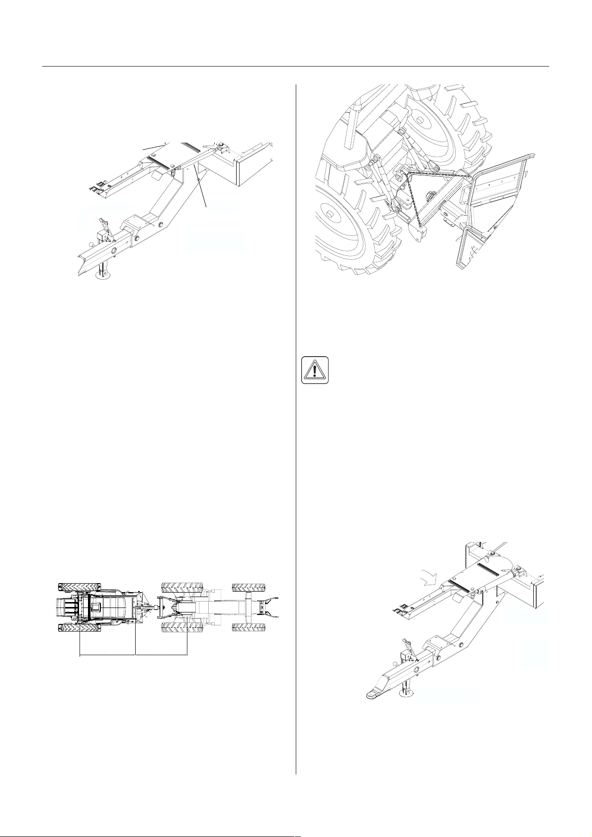
SELF TRACK is connected as follows:
1. Attach the tractor lower links in the two mountings of
the SELF TRACK. Adjust the length of the drawbar if
necessary - to obtain the best tracking, choose the
setting where the distance X is equal to distance Y.
Secure with linch pins.
2. Attach safety chains to top link clevis. The chain will
prevent the transmission shaft from being damaged if
the lift arms are lowered too far. Adjust the chain
length so the chains are tight when the tractor P.T. .
and pump shaft are in a horizontal line.
A
A
T251-0012x
xyT251-0015x
T251-0016x
NOTE! If possible, lock the tractor hydraulic lever when
the lift arms are in the correct position to avoid the
sprayer weight resting on the stabiliser chains.
3. Tighten the lift arm stabiliser chains.
WARNING! Do not stand in the area around the
drawbar during manoeuvring.
TRAIL CONTROLTRAIL CONTROL
TRAIL CONTROLTRAIL CONTROL
TRAIL CONTROL
Please refer to separate instruction book.
ose pacose pac
ose pacose pac
ose packk
kk
kaa
aa
agg
gg
ge suppore suppor
e suppore suppor
e support t
t t
t
To prevent hoses and wiring from being damaged by the
tractor wheels, all hoses, cables and wires are held by
the hose bracket A fitted to the drawbar.
Check that the length of the hoses and cables are
sufficient by tight turns.
T251-0012x
A
11
GB 05 03 01
Sprayer setup
TT
TT
Trr
rr
ransmission shaftansmission shaft
ansmission shaftansmission shaft
ansmission shaft
OperOper
OperOper
Operaa
aa
ator saftor saf
tor saftor saf
tor safetyety
etyety
ety
To avoid accidents and personal injuries, note the
following recommended precautions and safe operation
practices.
1. Always ST P ENGINE before attaching the transmis-
sion shaft to tractor P.T. . - most tractor P.T. . shafts
can be rotated by hand to facilitate spline alignment,
when engine is stopped.
2. When attaching the shaft, make sure that the snap
lock is FULLY ENGAGED - push and pull shaft until it
locks.
WARNING! R TATING TRANSMISSI N
SHAFTS WITH UT PR TECTI N GUARDS
ARE FATAL.
3. Always keep protection guards and chains intact and
make sure that it covers all rotating parts, including
CV-joints at each end of the shaft. Do not use without
protection guard.
4. Do not touch or stand on the transmission shaft when
it is rotating - safety distance: 1.5 meter.
5. Prevent protection guards from rotating by attaching
the chains allowing sufficient slack for turns.
6. Make sure that protection guards around tractor
P.T. . and implement shaft are intact.
7. Always ST P ENGINE and remove the ignition key
before carrying out maintenance or repairs to the
transmission shaft or implement.
InstallaInstalla
InstallaInstalla
Installation oftion of
tion oftion of
tion of tr tr
tr tr
transmission shaftansmission shaft
ansmission shaftansmission shaft
ansmission shaft
First installation of the transmission shaft is done in the
following way:
1. Attach sprayer to tractor and set sprayer height in the
position with shortest distance between the tractor
and sprayer pump P.T. . shafts.
2. Stop engine and remove ignition key.
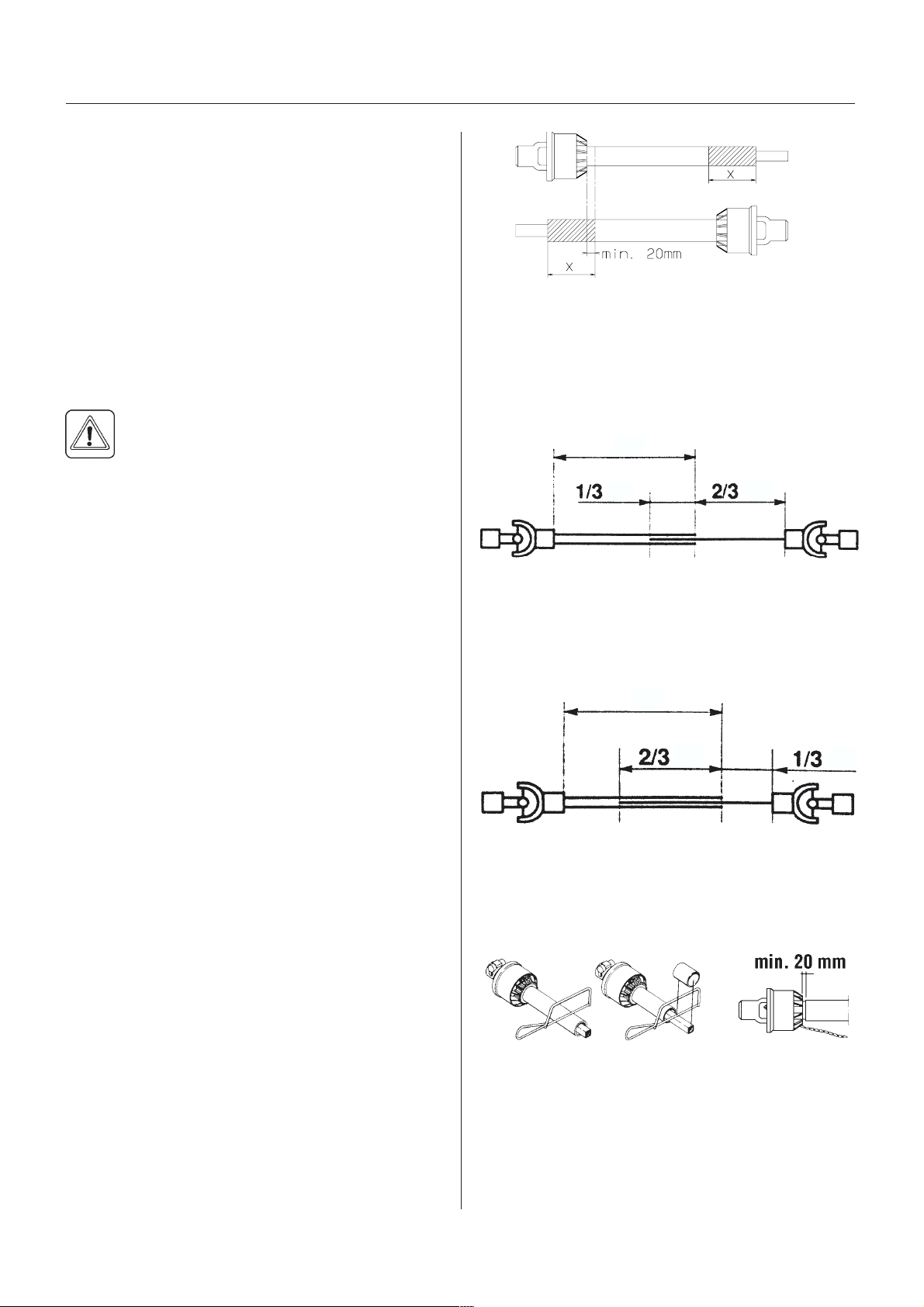
3. If transmission shaft must be shortened, the shaft is
pulled apart.
Fit the two shaft parts at tractor and sprayer pump
and measure how much it is necessary to shorten the
shaft.
Mark the protection guards.
NOTE! The shaft must always have a minimum overlap.
The size of this overlap depends on the pump model:
Pump with 6 splines/540 r.p.m.
The shaft must always have an overlap of minimum 1/3
of the length.
Pump with 21 splines/1000 r.p.m.
The shaft must always have an overlap of minimum 2/3
of the length.
4. The two parts are shortened equally. Use a saw, and
file the profiles afterwards to remove burrs.
5. Grease the tractor P.T. . and pump shafts.
6. Fit the shaft to tractor P.T. . and sprayer pump shaft.
NOTE: Female part marked with a tractor towards
tractor!
T259-0004
T259-0005 T259-0007
T259-0011
T259-0011
12 GB 05 03 01
Sprayer setup
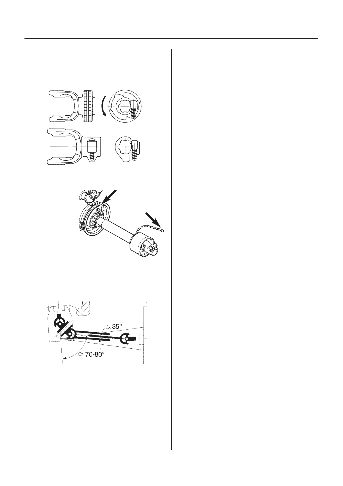
8. Twist the collar and slide the yoke onto the P.T. .
shaft.
Make sure that the lock engages by pushing and
pulling the shaft forwards and backwards.
9. Fit the chains to prevent the protection guards from
rotating with the shaft.
NOTE!To ensure long life of the transmission shaft try to
avoid working- angles greater than 35°. The wide angle
shaft with Constant Velocity Joint works in angles up to
70°- 80° for short periods (during turning etc.).
T259-0003
T259-0008
T259-0002
13
GB 05 04 04
Sprayer setup
T251-0005
TT
TT
Trr
rr
racac
acac
ac g g
g g
gaugaug
augaug
augee
ee
e
Altering the trAltering the tr
Altering the trAltering the tr
Altering the tracac
acac
ack gk g
k gk g
k gaugaug
augaug
augee
ee
e
The track gauge of the C MMANDER can be altered
stepless as follows,
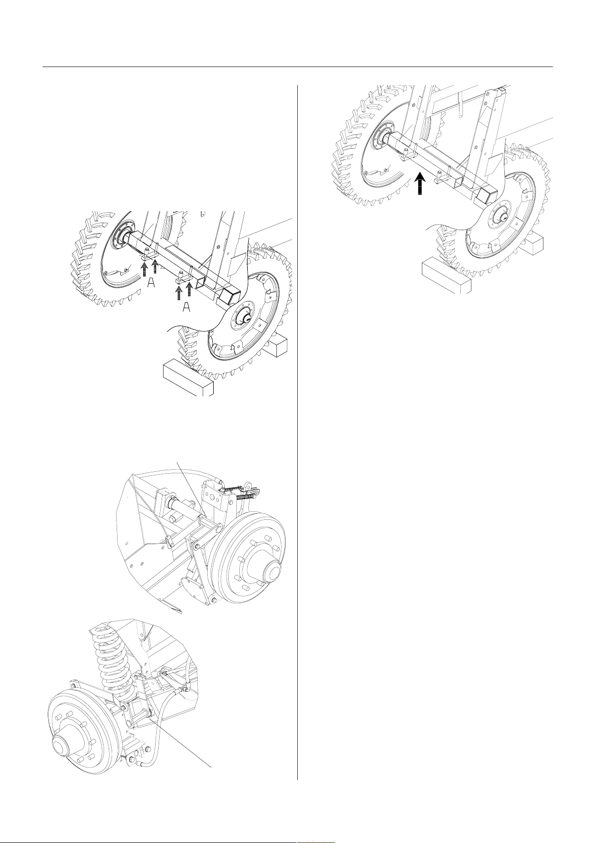
1. Measure the current track gauge (centre RH tyre to
centre LH tyre). Each side must be extended or
retracted half the desired alteration.
2. Attach the sprayer to tractor and engage tractor
parking brake.
3. Place stop wedges in front
of and behind RH wheel.
Jack up LH wheel, support
and secure sprayer body.
4. Loosen clamp bolts
for LH wheel axle.
5. Loosen the nut B on the brake operating arm.
Extend/retract this arm according to the adjustment of
the axle.
T251-0006
T112-0005x
T112-0005x
COMMANDER
without suspension
COMMANDER
with suspension
B
B
6. Extend or retract the axle.
A sack barrow and a
rod will facilitate the
operation.
7. If the rim position must be changed, do this first and
fine adjust by extending or retracting the axles.
Remember to tighten the wheel nuts to the specified
torque:
Rim plate to rim: 280 + 30 Nm (207 + 22 lbft)
Rim plate to hub: 490 Nm (288 lbft)
8. Tighten the clamp bolts to a torque of:
280 Nm (207 lb.ft) for 2200/2800
390 Nm (289 lbft) for 3200/4200.
9. Tighten nut B again.
IMPORTANT! Place the jack under the axle and lift the
wheel to remove load from the clamps before tightening
the clamp bolts to the specified torque.
10. Repeat the procedure on RH wheel.
11. Check the distance from centre tyre to centre of tank
frame is equal at RH and LH.
12. Retighten clamp bolts and wheel bolts to specified
torque after 8 hours of work.

14 GB 05 04 04
Sprayer setup
Adjustment rAdjustment r
Adjustment rAdjustment r
Adjustment rangang
angang
anges - tres - tr
es - tres - tr
es - tracac
acac
ack widthk width
k widthk width
k width
The maximum track width for all models is 2250 mm.
The minimum track width depends on the parameters in the charts beneath and whether the sprayer is equipped
with suspended axle or not. Please refer to the following charts (all figures are in mm).
Min. track width - Sprayers without suspension
&0SOXV 7\UHVL]H
Sprayer with: [ [ [ [ [ [ [
)ODQJHKXE
UDNHKXE
0XGJXDUGV
&0SOXV 7\UHVL]H
Sprayer with: [ [ [ [ [ [ [
)ODQJHKXE
UDNHKXE
0XGJXDUGV
&0SOXV 7\UHVL]H
Sprayer with: [ [ [ [ [ [ [
)ODQJHKXE
UDNHKXE
0XGJXDUGV
&0SOXV 7\UHVL]H
Sprayer with: [ [ [ [ [ [ [
)ODQJHKXE
UDNHKXE
0XGJXDUGV
&0SOXV 7\UHVL]H
Sprayer with: [ [ [ [ [ [ [
)ODQJHKXE
UDNHKXE
0XGJXDUGV
Min. track width - Sprayers with suspension

15
GB 05 04 04
Sprayer setup
T251-0003
T251-0004
PP
PP
Permitted rim positionsermitted rim positions
ermitted rim positionsermitted rim positions
ermitted rim positions
WARNING! When altering track gauge by turning
rims and rim plates the maximum permitted
offset between centre wheel and hub flange must
be observed:
Max offset, hub flange and centre rim:
IMPORTANT! Tyre sizes 18.4 x 38 and 20.8 x 38
are not permitted in any + position, only use the
- positions.
M Min. rim offset Max. rim offset
2200/2800 -45 +55
3200/4200 -33 +33
&0SOXV 7\UHVL]H
Sprayer with: [ [ [ [ [ [ [
)ODQJHKXE
UDNHKXE
0XGJXDUGV
&0SOXV 7\UHVL]H
Sprayer with: [ [ [ [ [ [ [
)ODQJHKXE
UDNHKXE
0XGJXDUGV
&0SOXV 7\UHVL]H
Sprayer with: [ [ [ [ [ [ [
)ODQJHKXE
UDNHKXE
0XGJXDUGV
It is not permitted to fit dual wheels!
IMPORTANT! n TRACKER models a minimum track gauge of 1800 mm is strongly recommended to ensure
stability and to avoid the sprayer tipping over.
NOTE! The wider the track gauge, the better the stability of the sprayer and boom.

16 GB 05 06 06
Sprayer setup
Load Sensing
Please consult your tractor dealer for correct setup and
correct connection.
Certain tractor models are able to use Load Sensing
without connecting an external sensing line (setting 1 in
scheme). But if optimal sensing control pressure cannot
be obtained, an external sensing line needs to be
mounted (setting 2 in scheme).
Requirements - Load Sensing hose:
1/4 Standard hose
Max. rated working pressure = 200 bar.
IMPORTANT! It is of essential importance that connec-
tors on sensing line are kept totally clean. Failure to do
so will cause impurities entering the pump and thereby
cause damages to vital pump parts.
029
ciluardyh/rocarT
mesys evlavegdirraC roalugerwolF
dradnaS
)rotcartwolftnatsnoc nepOnepO
ernecdesolC
)srotcartDJniatrec desolCdesolC
gnisnesdaoL
.1 tuohtiW lanretxe
enilgnisnes
nepOnepO
gnisnesdaoL
.2 htiW lanretxe
enilgnisnes
desolCnepO
Valve open
Valve closed
T112-0004x
Flow regulator
Cartri ge valve
T112-0004x
LS
Connect hose to
LS on the
distribution block
T112-0007x
HyHy
HyHy
Hydrdr
drdr
draulic syaulic sy
aulic syaulic sy
aulic systemsstems
stemsstems
stems
yy
yy
ydrdr
drdr
draulics COMMANDER- Aaulics COMMANDER- A
aulics COMMANDER- Aaulics COMMANDER- A
aulics COMMANDER- AYY
YY
Y
Tra tor Operated Hydrauli s
Connection requirements for C MMANDER-HAY are
one double acting and one single acting spool valve.
Single acting valve: Boom lift, up/down
Double acting valve: Boom folding and unfolding
Ensure the snap couplers are clean before connection!
If hydraulic slanting control is fitted another double acting
spool valve on the tractor is required.
NOTE! The hydraulic system requires a minimum oil
pressure of 130 bar, max. oil pressure of 210 bar and an
oil capacity of approx. 5 litres. After having operated the
boom and the system has been filled with oil, check
tractors hydraulic oil level and top up if necessary.
yy
yy
ydrdr
drdr
draulics COMMANDER- AZaulics COMMANDER- AZ
aulics COMMANDER- AZaulics COMMANDER- AZ
aulics COMMANDER- AZ
Dire t A ting Hydrauli system
The D.A.H. system requires a double acting hydraulic
outlet. The hydraulic hoses are marked with arrows to
indicate direction of oil flow.
The D.A.H. system requires an oil flow between 10 and
90 l/min (19.8 Imp. gal/min.) and a min. pressure of 130
bar (1886 p.s.i.) The system has a built-in flow regulator
that maintains constant speed on hydraulic movements.
The hydraulic distribution block is situated underneath
the platform floor.
The valves on the block are operated by means of
manual override and each valve can be regulated to be
open or closed.
Before operating the hydraulics, the valves on the
sprayers hydraulic distribution block should be adjusted
according to the specific tractor model (please refer to
scheme later in this part).
If you have doubt about which type of hydraulic system
your tractor is equipped with, please ask your tractor
dealer.

17
GB 05 06 06
Sprayer setup
ContrContr
ContrContr
Control bool bo
ol bool bo
ol boxx
xx
xes and powes and pow
es and powes and pow
es and power supplyer supply
er supplyer supply
er supply
Power requirement is 12V DC.
Note Polarity!
For EVC: Brown pos. (+), Blue neg. (-).
For D.A.H.: White pos. (+), Black neg. (-).
The control boxes for EVC-operating unit and D.A.H. are
fitted in the tractor cabin at a convenient place. Tapping
screws can be used for mounting.
The wires must have a cross sectional area of at least
4.0 mm to ensure sufficient power supply. For the EVC-
operating unit the tractor circuit should have an 8 Amp
fuse and for the D.A.H. an 16 Amp fuse.
Control box for Polarity (wire colour) Require Fuse, Amp
Positive + Negative -
EVC operating
unit Brown Blue 8
D.A.H. Hy raulic White Black 16
MANIFOLD valve Brown Blue 8
Use the HARDI Electric distribution box (No. 817925) if
the tractor has a doubtful power supply.
T165-0013

18 GB 05 05 02
Sprayer setup
WARNING! Do not connect the brakes directly to
the tractor hydraulics without the brake valve. The
trailer brake power cannot be controlled, and
braking will therefore be hazardous.
IMPORTANT! Max. oil pressure is 150 bar (2175 p.s.i.)
in the brake line.
Relieve parking brake before driving.
Air activAir activ
Air activAir activ
Air activaa
aa
ated brted br
ted brted br
ted brakak
akak
akes (ifes (if
es (ifes (if
es (if f f
f f
fitted)itted)
itted)itted)
itted)
This system requires a tractor with
compressor and air brake system with
out-let(s) for trailer brakes.
IMPORTANT! The load apportioning
valve must be set at the position
corresponding to the load on the
trailer, for obtaining optimal air pres-
sure to the trailer brakes.
= Relieved = Half full tank
= Empty tank = Full tank
WARNING! Driving with wrong load apportioning
valve setting, will make the brakes under- or over-
apply, which can cause hazardous situations.
NOTE! If the air hose(s) are disconnected with air in the
brake air tank, control pressure
will be dumped and the brakes
will engage fully. If the sprayer
must be moved with air in the
tank and without the air hose(s)
connected to the tractor, the load
apportioning valve must be set
at relieved to disengage the
brakes. Remember to reset the
handle to brake position again
afterwards. When parking the
sprayer, always engage the parking brake, as the air
brakes will only be engaged as long as there is air in the
tank! Cover the couplings with the dust flaps when
hoses are disconnected.
BrBr
BrBr
Braa
aa
a eses
eses
es
EmerEmer
EmerEmer
Emergg
gg
gencenc
encenc
ency and pary and par
y and pary and par
y and parkk
kk
king bring br
ing bring br
ing brakak
akak
ake (ife (if
e (ife (if
e (if f f
f f
fitted)itted)
itted)itted)
itted)
The parking brake lever has two function modes, which
are determined by the small pawl control clip (A).
To change between the
two modes, turn the clip.
Pos. 1: The pawl control
clip must point away from
the pawl.
Pos. 2: The pawl control
clip must rest against the
pawl.
To disengage the parking
brake:
1. Set pawl control clip in pos. 1.
2. Pull the lever a little forward to release the pawl from
the ratchet and then push the lever fully backwards.
To engage the parking brake:
1. Set pawl control clip in pos. 2.
2. Pull the lever firmly forwards until parking brake is fully
engaged.
Emergency brake
1. Set pawl clip in pos. 2.
2. Attach the rope from the hole in top of the handbrake
lever (B) to e.g. the tractor top link attaching point. If
the sprayer is accidentally unhooked during transport
the rope will apply the parking brake before the rope
breaks.
IMPORTANT! To ensure safe engagement and to avoid
damages to the parking brake use rope with an ultimate
stress between 690 N (155 lb.) and 785 N (176 lb.).
yy
yy
ydrdr
drdr
draulic activaulic activ
aulic activaulic activ
aulic activaa
aa
ated brted br
ted brted br
ted brakak
akak
akes (ifes (if
es (ifes (if
es (if f f
f f
fitted)itted)
itted)itted)
itted)
This requires a special trailer brake valve attached to the
tractor hydraulic and brake system. Connect the snap
coupler to the tractor brake outlet. When the tractor
brakes are applied, the trailer brakes will work propor-
tionally to the tractor brakes, and ensure safe and
effective braking.
T021-0001
T021-0008
Tractor Trailer
Hy raulic pump
Oil
reservoir
T021-0009
T021-0010
Position
setting
Loa valve
12
A
B
Forwar Backwar

19
GB 05 05 02
Sprayer setup
SingSing
SingSing
Single-line brle-line br
le-line brle-line br
le-line brakak
akak
akes (ifes (if
es (ifes (if
es (if f f
f f
fitted)itted)
itted)itted)
itted)
Flip the snap coupler protection flap away and connect
the brake system snap coupler to the tractor outlet
(black) and let the compressor fill the sprayers air
reservoir.
Check brake circuit for leaks.
Dual-line brDual-line br
Dual-line brDual-line br
Dual-line brakak
akak
akes (ifes (if
es (ifes (if
es (if f f
f f
fitted)itted)
itted)itted)
itted)
Flip the snap coupler protection flaps away and connect
the two snap couplers for supply and control to the
tractor outlets, and check brake circuits for leaks.
The couplers are colour coded and secured against
incorrect attachment:
Red = Supply line (RH)
Yellow= Control line (LH)
Relieve parking brake before driving

20 GB 05 10
Sprayer setup
Counter wCounter w
Counter wCounter w
Counter weight eight
eight eight
eight (TRA(TRA
(TRA(TRA
(TRACKER models only)CKER models only)
CKER models only)CKER models only)
CKER models only)
To improve stability on TRACKER models, extra weight
can be added by means of liquid-filled tyres.
The standard tyre valve is an universal air-water valve.
The tyres can be filled with liquid to max. 75% of their
total volume. The table below indicates the 75% volume.
Use a mixture of water and CaCl2 to avoid frost damage
as described in table below:
CaCl2 per litre water Protection to
200 g (7.1 oz) -15°C (30.6°F)
300 g (10.6 oz) -25°C (12.6°F)
435 g (15.4 oz) -35°C (-5.4°F)
WARNING! It is very important that the CaCl2 is
added to the water and agitated until it is fully
dissolved. Never pour water on to CaCl2! If you
get CaCl2 in the eyes, flush instantly with cold water for
at least 5 minutes and seek medical advice afterwards.
IMPORTANT! The tyres must be liquid filled to max. 75
% of total tyre volume. Fill only the qty. of liquid neces-
sary to obtain sufficient stability of the sprayer. Do not fill
liquid and CaCl2 mixture in tyres without tubes!
To fill the tyres:
1. Jack up the wheel
and rotate wheel till
the valve is posi-
tioned at 12 oclock.
2. Remove the valve
body and fill liquid
until it reaches the
valve.
3. When surplus liquid
is drained through the
valve stem fit the valve body again.
4. Adjust tyre pressure and lower the wheel. (Please
refer to table for correct tyre pressure).
NOTE! When filling the tyres the valve should be posi-
tioned at 12 oclock and when adjusting the tyre pres-
sure, the valve should be positioned at 6 oclock.
To empty the tyres:
1. Rotate wheel till the
valve is positioned at
6 oclock.
2. Remove the valve
body and let out the
liquid. Retain liquid in
an appropriate
container.
3. To empty the tyre
completely the tyre is
inflated and a thin drain
tube is lead to the
bottom of the tyre. The
air pressure will now
empty the remaining
liquid.
4. Remove the drain tube,
fit the valve and inflate
the tyre to specified
pressure. See the table Tyre pressure.
NOTE! Disposal of CaCl2 has to take place according to
local legislation.
T021-0011
T021-0013
T021-0014
001
eziseryT eryrepdiuqilfoseril.xaM
"44x5.9101
"84x5.9 801
"44x2.11331
"84x2.11 441
"64x4.21871
"83x9.61 582
"83x4.81093
"83x8.02 664
1 litre = 0.264 US Gal. 1 litre = 0.22 Imp. Gal.
eziseryT
59CR
dednemmoceR
nierusserpnoialfni
).i.s.p(rab
muminiM
xednIdaoL
2A/8A
44R59/032
)44x5.9 )256.3541/431
84R59/032
)84x5.9 )256.3 741/631
44R59/072
)44x2.11 )256.3151/041
84R59/072
)84x2.11 )256.3 351/241
64x4.21)256.3851/741
83x9.61 )326.1 251/141
83x4.81)326.1441/741
83x8.02 )812.1 151/451
Recommended tyre pressure:
002
Table of contents
Popular Lifting System manuals by other brands


Wesco
Wesco EVM 206-90 Use and maintenance instructions

ARJO HUNTLEIGH
ARJO HUNTLEIGH Voyager Portable Technical manual

Big Joe
Big Joe PTE 30 Series Operation, maintenance, repair parts list

Bend-Pak
Bend-Pak XPR-10A Service manual

Bigfoot
Bigfoot PLATINUM Series Installation & owner's manual

Bend-Pak
Bend-Pak HD-9SWX Service manual