ARJO HUNTLEIGH Voyager Portable User manual

Voyager Portable
Technical Manual
001.08875 rev. 10 July 2013

Design Policy and Copyright
® and ™ are trademarks belonging to the ArjoHuntleigh group of companies.
© ArjoHuntleigh 2012.
As our policy is one of continuous improvement, we reserve the right to modify designs without
prior notice.
The content of this publication may not be copied either whole or in part without the consent of
ArjoHuntleigh.

TABLE OF CONTENTS
INTRODUCTION.........................................................................................................................4
HOW TO USE THIS MANUAL ........................................................................................................................... 4
EQUIPMENT IDENTIFICATION.......................................................................................................................... 4
RECEIPT OF EQUIPMENT............................................................................................................................... 4
KEY TO SYMBOLS......................................................................................................................................... 4
SWL ........................................................................................................................................................... 4
SAFETY INSTRUCTIONS AND WARNINGS .............................................................................5
DESCRIPTION OF EQUIPMENT................................................................................................7
LIFT UNIT..................................................................................................................................................... 7
WHAT'S INCLUDED........................................................................................................................................ 7
PARTS DESCRIPTION .................................................................................................................................... 7
DIMENSION .................................................................................................................................................. 7
OPERATION...............................................................................................................................8
HOW TO USE THE VOYAGER PORTABLE ......................................................................................................... 8
BATTERY INFORMATION .......................................................................................................10
CHARGER SPECIFICATIONS......................................................................................................................... 10
CHARGING THE BATTERY............................................................................................................................ 11
MAINTENANCE........................................................................................................................11
DAILY CHECK LIST...................................................................................................................................... 11
INSPECTION AND CLEANING ........................................................................................................................ 12
STRAP INSPECTION .................................................................................................................................... 12
HANDLING AND STORAGE ........................................................................................................................... 12
BATTERY REPLACEMENT ............................................................................................................................ 12
ANNUAL INSPECTION ............................................................................................................13
STRAP REPLACEMENT................................................................................................................................. 13
DRUM REPLACEMENT ................................................................................................................................. 15
LIMIT SWITCH REPLACEMENT...................................................................................................................... 16
LIMIT SWITCH ROD REPLACEMENT .............................................................................................................. 17
SSRS BLOCK REPLACEMENT ..................................................................................................................... 18
MICA REPLACEMENT .................................................................................................................................. 22
CIRCUIT BOARD REPLACEMENT .................................................................................................................. 22
TOUCH PAD MEMBRANE REPLACEMENT....................................................................................................... 24
MAINTENANCE INSPECTION CHECKLIST ............................................................................26
TROUBLESHOOTING ..............................................................................................................27
ACCESSORIES ........................................................................................................................29

INTRODUCTION
4
001.08875 rev. 10
INTRODUCTION
How to use this Manual
DO NOT ATTEMPT TO USE THIS
EQUIPMENT WITHOUT UNDER-
STANDING THIS MANUAL.
To ensure safe operation, read carefully the
entire manual, especially the section on
“Safety Instructions and Warnings”, before
installing, operating, or servicing this
equipment.
If anything is not completely understood,
please contact your supplier for more
details. Failure to comply with warnings in
this manual may result in injury.
Keep this manual with the lift and refer to it
as required. Contents of this manual are
subject to change without prior notice to
users.
Throughout this manual, the following symbols
may appear. Pay particular attention to the
information provided under these headings. These
special annotations are easily recognized as
follows:
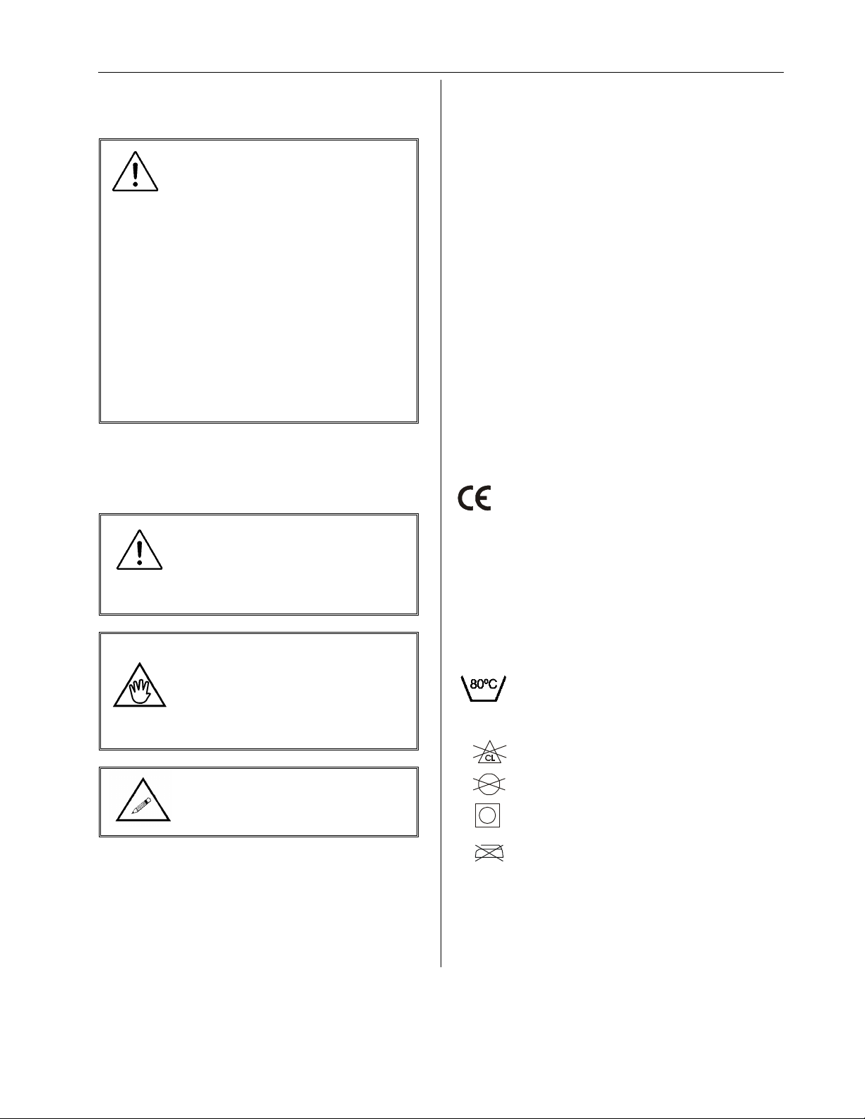
WARNING: this symbol is
intended to alert the user to
hazards or unsafe practices which
could result in serious bodily
harm.
CAUTION: this symbol is intended
to alert the user of the presence of
important operating and
maintenance instructions, which
could prevent product damage or
possible personal injury.
NOTE: this symbol offers helpful
information concerning certain
operating procedures.
Additional copies of this manual can be purchased
by contacting your supplier. Include the User
Manual product number and equipment
identification numbers.
Exploded view and parts list are available upon
request.
Equipment Identification
The unit's identification number (specification,
model, serial number) appears on a silver
nameplate attached to the back of base.
Receipt of Equipment
Upon receipt of the equipment, verify it against the
packing list to ensure it is complete and inspect
the equipment for possible damage due to
shipping. If there is any damage, DO NOT USE
the equipment and notify the carrier immediately
to file a claim. Provide complete information
concerning damage claims or shipping errors to
your supplier. Include all equipment identification
numbers and group part numbers (if any) as
described above along with a full description of
damaged parts.
Key to Symbols
THE FOLLOWING SYMBOLS ARE USED ON
LIFTER’S ATTACHMENT LABELS:
This symbol is required to be displayed on
regulated products for sale in the European
Market. It indicates that the product
complies with applicable European
Directives related to health, safety,
environment and consumer protection.
Safe Working Load represents the
maximum load the lifter is rated for safe
operation.
The following symbols are used on sling
labels and related to washing instructions:
Maximum washing temperature 80°C
(176°F) permanent cycle.
Do not use bleach.
Do not dry clean.
Tumble dry low temperature.
Do not iron.
Please refer to individual sling labels for complete
instructions regarding washing and drying.
SWL

SAFETY INSTRUCTIONS AND WARNINGS
5
001.08875 rev. 10
SAFETY INSTRUCTIONS AND WARNINGS
A.
GENERAL
IMPORTANT – READ THESE INSTRUCTIONS CAREFULLY OR SERIOUS INJURY MAY RESULT.
KEEP THESE INSTRUCTIONS AND THE KEY PROVIDED WITH THE LIFT AT ALL TIMES.
READ OPERATION AND MAINTENANCE INSTRUCTIONS IN THIS MANUAL BEFORE
INSTALLING, OPERATING, OR SERVICING THIS EQUIPMENT.
ArjoHuntleigh ceiling lifts are installed by an authorized contractor or installer
Your lift is for transferring patients only. Do not use the lift for any other purpose.
Always carry out the daily checklist before using the lift.
ArjoHuntleigh ceiling lifts are specifically designed for ArjoHuntleigh ceiling track systems,
slings and accessories. Slings and accessories designed by any other manufacturer are
prohibited and will void ArjoHuntleigh’s warranty. Use only ArjoHuntleigh slings and
accessories to maintain patient’s safety and product utility.
ArjoHuntleigh ceiling lifts are intended to be used for patients within the specified weight limit
indicated for the lift. Do not attempt to lift more than the weight limit indicated.
Before attempting to transfer, the patient must be assessed by a qualified professional.
ArjoHuntleigh ceiling lifts must be used by a caregiver with proper training to work with the
patient to be transferred.
ONLY trained and qualified caregivers should transfer a patient. DO NOT attempt to use the lift
if you have not been properly trained to do so. This patient lift should never be used by a
patient on his/her own.
ALWAYS be prepared before attempting to transfer a patient.
DO NOT use a sling that is not recommended for the lift.
NEVER use a damaged, torn or frayed sling.
Always place the sling around the patient according to the instructions enclosed.
FOLLOW lifting procedures outlined in this manual.
USE all controls and safety features only according to the rules specified in this manual.
Never attempt to force a control or button on the lift.
DO NOT store the charger in a shower, bath or other areas with high humidity.
DO NOT drop the patient lift or battery. Dropping the battery or lift may cause internal damage
that is not easily seen. If the lift is suspected to be damaged, contact an authorized technician
for servicing.
IMPORTANT: Keep all components of the lift clean and dry, and have electrical and mechanical
safety checkpoints done as instructed in the Maintenance section of this manual.
Replace any precautionary or instruction labels that cannot be easily read.
Avoid violent shock during transportation.
B. SHOCK PREVENTION
DO NOT touch or use a lift with bare conductors or a damaged power cord. Electrically live
equipment can electrocute a patient. If the lift or charger has any exposed or damaged wires
contact your local dealer immediately.
DO NOT cut or remove the round grounding prong from any plug. All ARJOHUNTLEIGH lifts
are equipped with three-prong plugs to protect from shock hazard or electrocution. Any two-
prong electrical outlet must be replaced with a properly grounded three-prong outlet according
to the National Electrical Code and local codes. It is the responsibility of the customer to have
the work done by a qualified electrician.
Do not splash or expose electric parts of the device to water or moisture.
Check nameplate for voltage and cycle requirements. These requirements differ by country.

SAFETY INSTRUCTIONS AND WARNINGS
6
001.08875 rev. 10
Do not attempt to use the lift in an area that has a different voltage and cycle requirement.
DO NOT attempt to expose service or repair the lift, battery or charger. If any unit is
malfunctioning, contact your local dealer.
READ the battery and charger instructions thoroughly before using or storing them.
C. FIRE AND EXPLOSION PREVENTION
Batteries may explode, leak and cause personal injury if not disposed of properly.
•Do not place or store the battery under direct sunlight or near a heat source
•Do not dispose of in fire
•Do not short the battery terminals
•Do not incinerate
•Flush with water if electrolyte (Acid) comes in contact with skin or eyes.
Batteries must be recycled, disposed of according to local law regulations. When returning
batteries, insulate their terminals with adhesive tape, etc. Otherwise, the residual electricity in
used batteries may cause fire or explosion.
D.
EQUIPMENT WARNING LABELS
Inspect all precautionary labels on the equipment. Order and replace all labels that cannot be
easily read.

DESCRIPTION OF EQUIPMENT
7
001.08875 rev. 10
DESCRIPTION OF EQUIPMENT
Lift Unit
The lift unit is an aluminium frame based system
driven by a gear reduced high torque motor.
OPERATING FEATURES
•Ultra-light: 5.45 kg (12 lb), battery included.
•Electronic soft-start and soft-stop motor
control.
•Easily accessible controls on both sides of
the unit.
•Manual emergency lowering device (in case
of electrical failure).
•Emergency brake (in case of mechanical
failure). Operates on the same principle as a
car safety belt mechanism.
•Quick-Release feature allows very fast
winding and unwinding of the strap before
and after transfer operation.
•Anti-crush feature stops the lift when there is
no tension on the strap, avoiding any injury
to the patient. This feature also prevents the
strap from getting twisted inside the
machine.
•Current limiter for circuit protection in case of
overload.
•Low battery disconnect system to protect
batteries from been drained.
•Lifting speed: 4 cm/sec. (1.6 in./sec.).
•Strap length up to 2.2 m (88 in). Tested for
907 kg (2000 lb).
•CSA No. 601.1, UL No. 2601-1 and CE
certifications.
•Respects EMI standards.
What's included
ITEM QTY
Voyager lift 1
Battery 1
Charger and Charge Monitor 1
Power cord 1
4 mm Allen key 1
Instruction manual 1
Parts Description
* Charger and adaptor’s appearance may differ depending on unit revision.
Dimension
4 mm Allen Key
Hook
Charger w AC adaptor *
Charge Monitor
Optional
Hand Control
Strap
Control
Buttons
Control
Buttons
Battery
Eject
Button
Carry Handle
Charge Indicator
Battery
Carry Bar
Carry Bar

OPERATION
8
001.08875 rev. 10
OPERATION
How to use the Voyager
Portable
READ "SAFETY INSTRUCTIONS
AND WARNINGS" BEFORE
ATTEMPTING TO USE THE
VOYAGER LIFT.
Always carry out the daily checklist before
each lift use.
Damage to the lift may occur if
not properly handled. Carry the
VOYAGER PORTABLE by its
handle only. Do not carry the lift
with the arm extension
accessory or other accessory
not intended to be used to carry
the lift.
1. Install the patient sling.
2. Take the battery out of the charger and
insert it into the lift. Make sure the silver
contact points go inside the lift.
3. Once the patient sling is installed, unwind
the strap.
There are two ways to unwind the strap:
First, you can press the button while
holding tension on the strap with the other
hand (there must be tension on the strap for
the lift to function).
The other way to do this is
to use the "QUICK-
RELEASE"; Push the knob
(1) and pull the strap out of
the lift (2).
Push knob completely over to
ensure the QUICK-RELEASE will
work properly.
QUICK-RELEASE will not work if
there is tension on the strap.
Make sure the strap has some
slack in it before attempting to
slide the knob over.
DO NOT force the knob. It should slide
easily.
4. Attach the round hook to
the trolley in the track.
To help you reach the trolley, use
the arm extension as follows:
Insert the round hook into the loop of the arm
extension #700.08310 (1), then hook it to the
trolley in the track (2).
(1) (2)
5. Move the lift over to the patient.
Hold the lift with one hand at all
times when near a patient.
6. Lower the lift below the chin before
beginning to attach the sling straps (this is
to avoid the risk of facial contact caused by
movement of the lift).
For a patient in a lying position, lower the lift
near the thorax, and then install the straps.
7. Attach the straps of the sling for the sling to
be used.
8. Lift the patient slightly by pressing the
button.
BEFORE LIFTING THE PATIENT:
1. Make sure that all straps are
attached to the carry bar.
2. Make sure the patient's arms
are safely out of the way.
3. Make sure the sling is not
caught on an obstruction
(wheelchair brake or arm of
chair).
If any of the above occurs – lower the
patient immediately and correct the
problem.

OPERATION
9
001.08875 rev. 10
9. Lift until the patient's buttock
clears the arm supports or the
top of the bath or bed before
moving the patient. Guide the
legs past any obstacle.
10. When the patient is located
above the desired point of
transfer and ready to be
lowered, press the button.
11. Use the handles on the back of the
sling to position the patient when transferring
into a chair. Hold the handles firmly as the
sling lowers and the sling will tilt back to
position the patient.
12. Once the patient is properly seated and the
straps are loose, remove the sling from the
lift.
Hold the lift with one hand at all
times when near a patient.
13. Slide the lift away from the patient.
14. Unhook the lift from the
trolley in the track and use
the "QUICK RELEASE" to
shorten the strap. To do
so, push the knob (1) and
hold the strap while it
winds itself into the lift.
Push the knob completely over
to ensure the "QUICK-
RELEASE" will work properly.
"QUICK-RELEASE" will not work
if there is tension on the strap.
Make sure the strap has some
slack in it before attempting to
slide the knob over.
DO NOT force the knob. It should slide
easily.
When using the "QUICK-
RELEASE" hold the strap in your
hand and release the knob (1)
only when the strap is not going
in motion. This will prevent wear
of the internal components.
15. The sling may be removed from around the
patient.
Emergency Lowering Feature
In the event of an electrical or functional failure,
the Voyager Portable has an emergency
manual-lowering feature.
If the lift malfunctions when a patient is being
transferred, the emergency manual lowering
device provides a safe way of lowering the
patient onto a chair or bed.
To operate the emergency lowering feature:
1. Find the rubber stopper and label on the side
of the lift.
2. Pull the rubber stopper out of the Voyager
Portable casing – DO NOT DISCARD.
3. Move the patient over a bed or chair.
4. Using the Allen key provided with this
manual, turn the key clockwise to lower the
patient into the chair. As the key turns the
motor directly, each key turn will move the
patient slightly.
5. Once the patient is lowered safely into a
chair or bed, take the lift to a certified
technician to be serviced.

OPERATION
10
001.08875 rev. 10
Battery Information
DO NOT DROP BATTERY. A
DROPPED BATTERY MAY HAVE
INTERNAL DAMAGE THAT IS
NOT VISIBLE. IT MAY LOSE ITS
ABILITY TO RECHARGE.
Due to internal damage caused when the
battery is dropped, the battery may
indicate that it is fully charged, when in
fact the battery cannot hold a full charge.
A green light indicated on the charger
may not accurately reflect a full charge on
a damaged battery.
NEVER attempt to use a battery that
appears to be damaged or dented.
DO NOT store battery near a heat source.
Heat will damage the battery.
Always keep metal battery contacts clean.
•24 Vdc, 2.0 Ah interchangeable and
rechargeable battery.
•Provides 10 to 30 transfers per battery
charge (may vary depending on patient
weight and battery condition. See graph
below).
Life cycle (number of charging cycles) of the
battery is largely dependent on the depth of
discharge in each cycle. The more the battery is
drained, the shorter its life’s span. The life of the
battery is also related to such factors as varying
temperatures and rest periods between charge
and discharge.
Graph 1: Number of recharge vs. Depth of
discharge
0
20
40
60
80
100
120
Charge/discharge cycles
100
50%
30%
%
200
400
600
800
1000
1200
0
GRAPH #1 illustrates the relationship between
discharging depth and expected battery life.
If you use only 30% of the battery power
between each charge, you can expect the
battery to fully charge 1050 times.
If you drain the battery until it beeps every time,
you can expect the battery to fully charge only
300 times.
To prolong battery life - Put the
battery into the charger
WHENEVER THE LIFT IS NOT IN
USE.
The battery will not overcharge.
ARJOHUNTLEIGH uses sealed lead-acid
batteries. Contrary to nickel-cadmium,
ARJOHUNTLEIGH batteries do not have any
memory effect. Therefore, batteries should
not be completely drained before recharge.
Graph 2: Number of lifts vs. Lift load
The graph above (GRAPH #2) illustrates the
relationship between the load lifted and the
number of lifts that can be done with one
recharged battery.
Do not drain the battery
excessively. This will
dramatically reduce the battery
life’s span.
If the low battery buzzer sounds, be sure
to recharge the battery as soon as
possible.
Charger Specifications
#700.13500
•Class 2 power cord rated at 2.5 A
(100-240 Vac 50-60 Hz).
•Charger input: 100-240 Vac,
50-60 Hz, 50VA
•Charger output: 27 Vdc 1A.
#700-24201
•Class 2 double insulated
•Charger input: 100-240 Vac,
50-60 Hz
•Charger output: 28.1 Vdc, 1A.
•Used with charge monitor
#700-13501
#700-15567
•Class 2 double insulated
•Charger input: 100-240Vac,
50-60 Hz
•Charger output: 24Vdc, 24VA, 1A
•Used with charge monitor
#700-13501
0
10
20
30
100 200 300 440
weight (lb s.)

MAINTENANCE
11
001.08875 rev. 10
Charging the Battery
Check to make sure the green light on the
charger is illuminated. This indicates that the
charger is on.
•Insert the battery into the charger with the
silver contact points of the battery going into
the charger.
•The charging indicator light will flash yellow
while the battery is charging. If the battery is
fully charged, the charging indicator light will
illuminate solid yellow.
•If the battery is completely depleted, it will
take up to 6 hours to recharge.
•If the battery is low, it will take approximately
2 hours for a full charge.
Whenever possible, leave the
battery in the charger when the
lift is not in use.
At minimum, charge the battery until the
light is solid yellow (not flashing) before
using again. This will extend the life of the
battery.
•When the lift is needed again, pull the
battery out of the charger and, gently slide it
back into the Voyager Portable lift. The silver
contacts should be inside the lift.
•The charger can remain plugged into the
wall indefinitely, convenient for overnight
recharging.
•The battery can be left in the charger for an
extended period of time without damaging
either the charger or battery.
•If the green light does not go on when the
charger is plugged into an electrical outlet,
see “Troubleshooting” section.
MAINTENANCE
ALWAYS CARRY OUT THE DAILY
CHECKLIST BEFORE EACH LIFT
USE.
DO NOT attempt to open the VOYAGER
PORTABLE. Only a certified technician is
authorized to open the VOYAGER PORTABLE.
Alterations made to the VOYAGER PORTABLE
by someone other than a certified technician
may cause serious injury.
VOYAGER PORTABLE and accessories must
be inspected ANNUALLY by a certified
technician in addition to the daily and other
periodic visual checks done by the user specified
in this section.
Preventive maintenance specified in this manual
can prevent accidents and reduce repair costs.
Daily Check List
THE FOLLOWING PROCEDURE MUST BE
FOLLOWED BEFORE EACH USE.
•Has the battery been charged? Charge the
battery whenever the lift is not in use.
•Inspect the battery before placing it in the
Voyager portable. If the battery appears to
have any damage – DO NOT USE IT. Replace
the battery immediately.
•Inspect the lift for any damage. If the lift casing
does not look properly aligned, or there are any
cracks or other damage on the lift, or any parts
are missing - DO NOT USE IT. Contact your
local representative to have the lift serviced.
•Attach the lift to the trolley in the track. Inspect
the visible strap for any signs of wear, frays,
loose threads or other damage. If there is any
evidence of damage- DO NOT USE IT.
Contact your local representative to have the
lift serviced.
•Inspect the sling for tear, frayed straps or loose
stitching. If the sling has any of the above
damage –DO NOT USE IT. Contact your local
representative to have the sling replaced or
repaired.
•Inspect the arm extension and the adjustable
extension strap (if you have these options) for
wear. Check the adjustable extension strap for
frays or loose stitching. Check the arm
extension for damage in the metal hook or
handle. DO NOT USE if there is any damage.
•Inspect the hook at the top of the strap to
ensure it is properly attached and there is no
damage to the hook.
GREEN
LIGHT –
Power is on
Solid yellow light indicates that battery
charging is completed Flashing yellow
light indicates that battery is charging

MAINTENANCE
12
001.08875 rev. 10
Inspection and Cleaning
Clean the VOYAGER body with a dry soft cloth,
or a soft cloth lightly moistened with a mild
detergent solution. Do not use any type of
solvent that may damage the finish.
DO NOT immerse lift in water.
To ensure a better rolling surface for the trolley
wheels, clean the inside of the track every
4 months. To do so, insert a damp cloth in the
opening and slide it from one end of the track to
the other.
Always reinstall the track end
stopper (if they have been
removed) after servicing.
Strap Inspection
This equipment is built with a strap that can
withstand a load of 907 kg (2000 lb)
Nonetheless, if this strap is damaged or shows
signs of wear the acceptable load on the strap
before rupture can drop rapidly and present a
danger for the patient or caregiver.
ArjoHuntleigh recommends thoroughly
inspecting the strap every 2 months as follows:
1. Completely unwind the strap.
2. Look for any signs of wear.
Loose threads in stitched area.
Noticeable discoloration by having
a lighter color strap than the double
Side wear.
Middle wear.
thickness stitched area.
If there are any signs of wear as
indicated here or other visual
defects, strap should be
changed immediately. By
continuing to use the lift without
changing the strap, caregiver
and patient safety is greatly
compromised.
In any case, the manufacturer
recommends changing the strap at least
every two years. By continuing to use the
lift without changing the strap, caregiver
and patient safety is greatly
compromised.
Handling and Storage
Avoid violent shock during transportation.
The lift should not remain stored for long periods
of time without recharging the batteries.
ArjoHuntleigh
recommends
charging of bat
teries at least
every two weeks
even if the lift is
not used. This will prevent
premature aging of batteries.
Battery Replacement
ARJOHUNTLEIGH uses sealed lead-acid
batteries. Contrary to nickel-cadmium,
ARJOHUNTLEIGH batteries do not have any
memory effect. Therefore, batteries should not
be completely drained before recharge.
Replace the battery when it has been dropped or
if there is a noticeable reduction in the number of
transfers that can be performed between
charges. If you notice the Voyager Portable is
“beeping’, see the instructions in
“Troubleshooting” section to ensure it is a
problem with the battery.
To replace a battery, contact your local dealer or
representative.
DO NOT ATTEMPT TO USE A
BATTERY NOT AUTHORIZED BY
ARJOHUNTLEIGH.
ARJOHUNTLEIGH batteries are specially
designed for ARJOHUNTLEIGH charging
systems. Attempting to use an
unauthorized battery may seriously
damage the lift and/or the charger.

MAINTENANCE
13
001.08875 rev. 10
Annual Inspection
The Voyager Portable and its accessories must
be inspected annually by a certified technician.
VOYAGER PORTABLE AND
ACCESSORIES MUST BE
SERVICED EVERY 12 MONTHS AS
A MINIMUM REQUIREMENT.
Do not attempt to do the inspection unless
you are certified to do so.
As part of the annual inspection, an annual
load test with the safe working load must be
performed on the VOYAGER PORTABLE as
required for CE MARK MAINTENANCE.
Strap replacement
1. Stand up the VOYAGER on a solid table.
Remove the hook. Remove the strap guide
by unscrewing the 2 screws.
2. Put the VOYAGER on the back and unscrew
the 2 screws on the carry handle and the
2 screws at the bottom of the device.
3. Flip the VOYAGER and put it on its front.
Unscrew the Quick Release button, the
4 screws on the cab and the 2 screws on the
carry handle.
Gently, remove the rear cab from the
Voyager. Just lift enough the frame from the
front cab to unplug the 2 control switch
connectors from the circuit board. Stand up
the frame on a solid surface. Be careful with
the circuit board under the frame.
4. Temporarily screw the Quick Release knob
and with one hand activate the Quick
Release and with the other pull out the entire
strap from the drum.
Look at the two holes on the frame (battery
side) and align the two bolts of the drum by
turning the drum.

MAINTENANCE
14
001.08875 rev. 10
5. Unscrew the long bolt from the drum.
Activate the Quick Release and pull the
strap just enough to make half turn to the
drum and align the other screw with the first
hole of the frame. Be sure the Quick
Release is in correctly. Unscrew the drum
bolt and remove the strap.
6. Install the strap in the drum (loop outside)
and screw the first bolt through the strap to
the drum.
Make half turn to the drum and screw the
other bolt to the drum.
Insert the other end of strap through the limit
switch hole. With one hand insert the end of
strap and with the other hand one finger
push the limit switch and another finger
guide the strap through the hole.
Pull out the entire strap from the frame. Hold
the end of strap, activate the Quick Release
and let the entire strap roll on the drum.
7. Unscrew the Quick Release button. Gently
put the frame in the front cab just enough to
plug the 2 control switches like step 3. Place
the carry handle in the front cab. Place the
rear cab and screw a few thread of all
6 screws front the rear cab. Tighten the
Quick Release button.
8. Flip the Voyager. Unscrew a few threads of
all the 4 screws from the front cab. Install the
strap guide and screw it. Align the cab and
tight the 4 carry handle screws. Tighten the
2 center screws from the rear cab.
9. Flip the Voyager to the front. Screw the
2 screws at the bottom of the cab. Verify the
eject battery button for working properly.
10. Stand up the Voyager. Pull on the strap and
verify the Quick Release for proper
operation.
11. Tighten both screws one after the other
while checking the Quick Release to make

MAINTENANCE
15
001.08875 rev. 10
sure it is not stuck. If stuck, unscrew a little
until Quick Release is functional.
Drum Replacement
1. Do step 1 to 3 from the strap replacement
instructions.
2. Rewind the entire strap on the drum and fix it
with tape. Temporarily screw the Quick
Release knob. Activate the Quick Release
with one hand and with the other slow the
drum to permit to remove the 4 turns of pre-
load until you place in front of you the spring
screw.
3. Unscrew the spring screw just enough to
loosen the sprint. With a pair of pliers, grab
the spring and locate it on the frame wall as
shown.
4. Remove the circlip on the center shaft of
drum and pull out the shaft through the
frame.
5. Pull out the drum from the frame. Be careful
not to loose any parts.
6. Unscrew the spring screw on the former
drum and fix it to the new one, just a few
threads. Install the new drum. Hold the
washer and spring to the drum with a
screwdriver or home knife and insert the
drum in the frame. You may have to push on
the "Quick Release" button.
7. Reinstall the center shaft trough the frame
and lock with the clip. With a pair of pliers
grab the spring and locate it on the screw to
the frame. Tighten the spring screw.
8. Activate the Quick Release button with one
hand and with the other turn the drum to
permit to put the 4 turns of pre-load until you
place in front of you the strap end and pass
the strap through the limit switch hole.
9. Unscrew the Quick Release button. Gently
put the frame in the front cab just enough to
plug the 2 control switches like step 3.
10. Place the carry handle in the front cab. Place
the rear cab and screw a few threads of all
SPRING

MAINTENANCE
16
001.08875 rev. 10
6 screws in front the rear cab. Tighten the
Quick Release button.
11. Flip the Voyager. Unscrew a few threads of
all the 4 screws from the front cab. Install the
strap guide and screw it. Align the cab and
tight the 4 carry handle screws. Tighten the
2 center screws from the rear cab.
12. Flip the voyager to the front. Screw the
2 screws at the bottom of the cab. Verify the
eject battery button for working properly.
Limit Switch Replacement
1. Stand up the Voyager on a solid table.
Remove the Hook and remove the strap
guide by unscrewing the 2 screws.
2. Put the Voyager on the back and unscrew
the 2 screws on the carry handle and the
2 screws at the bottom of the device.
3. Flip the Voyager and unscrew the Quick
Release button, the 4 screws on the cab and
the 2 screws on the carry handle.
4. Stand up the Voyager. Pull on the strap and
verify the Quick Release for proper
operation.
5. Tighten both screws one after the other
while checking the Quick Release to make
sure it is not stuck. If stuck, unscrew a little
until Quick Release is functional.
6. Gently, remove the rear cab from the
Voyager. Just lift enough the frame from the
front cab to unplug the 2 control switches
connector from the circuit board. Stand up
the frame on a solid surface. Be careful with
the circuit board under the frame
7. Unscrew the 2 screws on the limit switch
with a flat tip screwdriver and the appropriate
key.

MAINTENANCE
17
001.08875 rev. 10
8. Unplug the 2 blue wires from the limit switch.
9. Replace the limit switch by a new one and
plug back the 2 blue wires on both end of the
limit switch.
10. Screw back in the 2 screws on the limit
switch.
11. Gently put the frame in the front cab just
enough to plug back the 2 control switches
to the board. Place the carry handle in the
front cab. Place the rear cab and screw a
few thread of all 6 screws front the rear cab.
Tighten the Quick Release button.
12. Flip the Voyager and unscrew a few threads
of all the 4 screws from the front cab. Install
the strap guide and screw it. Align the cab
and tight the 4 carry handle screws. Tighten
the 2 center screws from the rear cab.
13. Flip the Voyager to the front. Screw the 2
screws at the bottom of the cab. Make sure
the eject battery button is working properly.
14. Stand up the Voyager. Pull on the strap and
verify the Quick Release for proper
operation.
15. Tighten the two screws under the Quick
Release while checking if the Quick Release
is moving freely. If stuck, unscrew a little
until the Quick Release is functional.
Limit Switch Rod Replacement
1. Do steps 1 to 7 from the limit switch
replacement instructions.
2. Remove the spring from the limit switch rod.
3. Drill out the rivet from the other side and
remove the limit switch rod.

MAINTENANCE
18
001.08875 rev. 10
4. Insert the new rod. Insert the rivet in the rod
hole and pop up the rivet.
5. Put the spring back on the limit switch rod.
6. Do steps 11 to 15 of the limit switch
replacement instructions.
SSRS Block Replacement
1. Stand up the Voyager on a solid table.
Remove the hook and remove the strap
guide by unscrewing the 2 screws.
2. Put the Voyager on the back and unscrew
the 2 screws on the carry handle and the
2 screws at the bottom of the device.
3. Flip the Voyager and unscrew the Quick
Release button, the 4 screws on the cab and
the 2 screws on the carry handle.
4. Gently, remove the rear cab from the
Voyager. Just lift enough the frame from the
front cab to unplug the 2 control switch
connectors from the circuit board. Stand up
the frame on a solid surface. Be careful with
the circuit board under the frame.
5. Unscrew the “no 25 Torx screw”. The
electric board does not need to be
unplugged. It only needs to be removed from
the frame so the SSRS block can be reach.

MAINTENANCE
19
001.08875 rev. 10
6. Unplug the blue and white wires plug.
7. Unscrew the two small limit switch bolts and
remove the limit switch’s board.
8. The next step would be to remove the drum.
First, rewind the entire strap on the drum
and fix it with tape. Temporarily screw the
Quick Release knob. Activate the Quick
Release with one hand and with the other
slow the drum to permit to remove the 4
turns of pre-load until you place in front of
you the spring screw.
9. Unscrew the spring screw just enough to
loosen the sprint. With a pair of pliers, grab
the spring and locate it on the frame wall like
showed.
10. Remove the clip on the center shaft of drum
and pull out the shaft through the frame.
11. Pull out the drum from the frame. Be careful
not to loose any parts.
12. Once the drum is removed, the next step is
to pull out the electric motor. First, unplug
the two wires attached to the motor.
SPRING

MAINTENANCE
20
001.08875 rev. 10
13. Unscrew the 3 motor bolts and pull it out
from the frame. When you pull out the motor,
make sure the shaft stay assembled with the
motor. The bearing does not need to stay
with the shaft.
14. Uncouple the spring (1) that holds the CBLM
plate (2) and unclip the SSRS bloc (3) from
the CBLM plate (2). To unclip it, while
holding the CBLM plate, push the block out.
15. Replace the SSRS block and clip the new
block in the slot of the CBLM plate. To clip
the block, make sure to push the plate in the
bottom of the SSRS block slot.
16. Put the bearing, shaft and motor in place.
The bearing has to be placed between the
brass bushing and the shaft with the writing
on the bearing against the frame.
17. Reinstall the drum. Hold the washer and
spring to the drum with a screwdriver or
home knife and insert the drum in the frame.
You may have to push on the "Quick
Release" button.
Other manuals for Voyager Portable
1
Table of contents
Other ARJO HUNTLEIGH Lifting System manuals

ARJO HUNTLEIGH
ARJO HUNTLEIGH Alenti User manual

ARJO HUNTLEIGH
ARJO HUNTLEIGH Maxi Sky 1000 User manual

ARJO HUNTLEIGH
ARJO HUNTLEIGH MAXI MOVE User manual

ARJO HUNTLEIGH
ARJO HUNTLEIGH Maxi Sky 2 User manual

ARJO HUNTLEIGH
ARJO HUNTLEIGH Maxi Twin User manual

ARJO HUNTLEIGH
ARJO HUNTLEIGH EASYTRACK FS User manual

ARJO HUNTLEIGH
ARJO HUNTLEIGH maxi sky 440 User manual

ARJO HUNTLEIGH
ARJO HUNTLEIGH maxi sky 440 User manual

ARJO HUNTLEIGH
ARJO HUNTLEIGH Maxi Sky 2 User manual

ARJO HUNTLEIGH
ARJO HUNTLEIGH Malibu Sovereign Operating instructions