HARDKORR HKPINVAC1000 User manual
V1.0 - 8.2023
HKPINVAC1000 / HKPINVAC2000 / HKPINVAC3000
USER MANUAL
PURE SINE INVERTERS
WITH AC TRANSFER SWITCH

In doing so, you now have the assurance and peace of mind that comes from
purchasing a product that has been manufactured to the highest quality standards.
Our aim is for you to be completely satisfied with your purchase, and therefore your
new Hardkorr product is backed by a comprehensive warranty and an outstanding
after-sales customer service team.
We hope you will enjoy using this product for many years to come.
If you require technical support, or in the unlikely event your purchase appears to be
faulty, please contact our support team for immediate assistance. Contact details for
each country are contained within this user guide.
iWELCOME TO HARDKORR
CONGRATULATIONS ON
PURCHASING THIS HIGH QUALITY
HARDKORR PRODUCT!

For assistance with assembly or installation, parts and service, please visit www.hardkorr.com or
contact customer service through the following:
ii
Toll Free:
1800 533 544
Monday - Friday
9AM - 4PM (AEST)
Language spoken: English
support@hardkorr.com
SAFETY INSTRUCTIONS 1
OVERVIEW 2
SPECIFICATIONS 5
INSTALLATION 7
INSTALLATION - DC 8
INSTALLATION - AC 13
INSTALLATION - REMOTE 15
OPERATION 16
AC OUTPUT 17
ECO MODE 18
SCREEN NAVIGATION 19
FAULT CODES 21
WARRANTY INFORMATION 23
CONTENTS
DISCLAIMER
While caution has been taken to ensure the accuracy of the contents of this guide, Hardkorr assumes
no responsibility for errors or omissions. Please note that specifications and product functionality may
change without notice.

1SAFETY INSTRUCTIONS
• Before installing or using the product, ensure you have read and understood all of the warning and
safety messages supplied with your product.
• Our range of inverters should be installed by licensed professionals only.
• Before installing, cleaning, or inspecting the unit for maintenance, ensure that the inverter is
disconnected.
• Children, those without the proper training or experience, or those under the influence of drugs or
alcohol should not operate this unit.
• Before wiring up the inverter, make sure to inspect your leads to make sure they are free from faults
or frays. The cables used to connect the battery to the inverter need to be of a particular gauge.
Consult the wiring guide found in this manual for more information. Failure to use leads fit for
purpose may cause fire, shock, or damage to the unit.
• Reverse polarity will cause the inverter’s fuses to blow and may damage the inverter. Make sure to
pay close attention when hooking up the inverter, ensuring that the negative and positive terminals
are clean and are connected to the correct corresponding battery terminals.
• It’s common for the inverter to arc when wiring up the final connection. Make sure to keep any
flammable materials away from the installation area.
• Do not store or operate the inverter in a location where it may be subject to water, temperatures
below -20°C or above 40°C, or in areas where it's at risk of contacting chemicals, fumes, or gases.
• The inverter contains sensitive electrical equipment which may be damaged if the unit is subjected to
pressure or impact. Ensure that the inverter is securely mounted to prevent it from falling.
• The inverter should be installed in a way that allows for proper ventilation around the unit. Ensure
that the fans and vents are not obstructed. We recommend having at least 100mm of clearance
around the unit to allow for adequate airflow.
• The inverter should only be used with appliances that are in safe working condition. Make sure to
inspect both the wattage of the appliance and its leads and wires before operating.
• The inverter generates AC 240V power which, in extreme situations, can cause severe injury or
death. Whilst the inverter has been engineered with advanced internal protections, caution should
be used when operating the unit. Metal objects (except for dedicated plugs) should be kept away
from the inverter’s ports.
• The inverter should not be opened or disassembled under any circumstance. Doing so will void the
warranty and may cause damage/injury to those in proximity.
IMPORTANT, RETAIN FOR FUTURE REFERENCE: READ CAREFULLY
2OVERVIEW
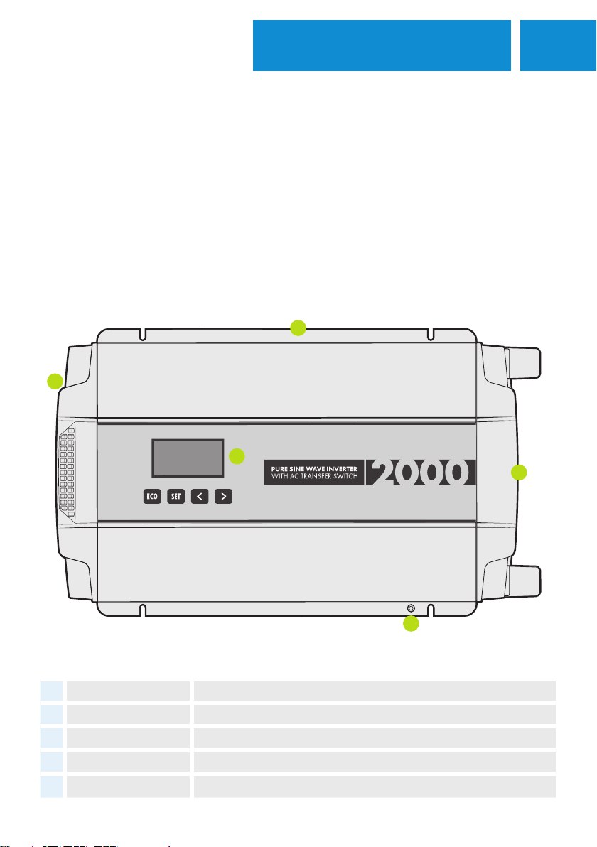
PRODUCT OVERVIEW
3
1
4
5
2
# ITEM DESCRIPTION
1Output side On/off switch, RCD switch, and 240V output access.
2Input side Positive/negative terminals, IEC UPS connection, and inverter remote port.
3Mounting flange Used for mounting inverter to surface.
4Grounding terminal Screw on port used to earth the inverter.
5Inverter display Displays live information of inverter power usage - 2000W & 3000W only.
Our Pure Sine Wave Inverters are designed to convert your 12V power, from your battery system, into safe
and reliable 240V power. This allows you to operate appliances you’d usually run off AC/mains power from
the comfort of your caravan, camper, or touring setup wherever you’ve decided to set up.
The units are equipped with an AC Transfer Switch feature. Particularly useful when you’ve set up at a powered
site at a caravan park or decided to run the generator, the inverter will seamlessly transition from running via
12V to AC input. The feature assists in conserving your batteries by creating a more efficient transfer of power.
PURPOSE
3OVERVIEW
2
7
6
9
10
1
5
8
3
4
INPUT
OUTPUT
1000W only
3000W only
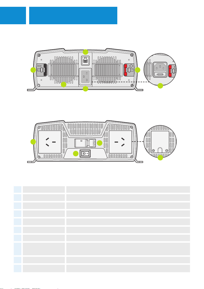
# ITEM DESCRIPTION
1Positive terminal Direct connection for positive lead from battery.
2Negative terminal Direct connection for negative lead from battery or shunt if connected.
3RJ12 port Used for connecting the inverter remote control.
4IEC-C20 socket Connects inverter to 240V AC power - 2000W & 3000W only.
5IEC-C14 socket Connects inverter to 240V AC power - 1000W only.
660mm fan exhaust shroud Removes hot air from inverter case. DO NOT COVER.
7Type I 240V socket Used for connecting appliances to the inverter.
8Hard wire terminal block Allows hard-wired connection for caravans - 3000W inverter only.
Installation is to be performed only by a licensed electrician.
9RCD protection switch Shuts electrical supply off when earth leakage is detected.
10 Inverter on/off switch Turns on/off inverter.
4OVERVIEW
1
6
3
4
5
87
2
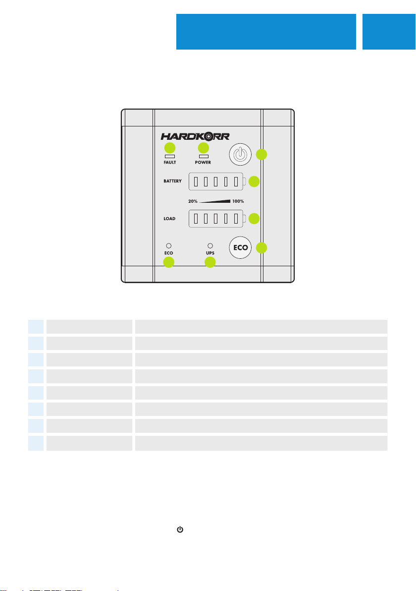
INVERTER REMOTE CONTROL OVERVIEW
OPERATING THE REMOTE
The inverter remote gives you the ability to operate the inverter’s basic features in a more convenient location.
For the remote to work, the power switch on the inverter must be turned on.
To turn the inverter on/off, press and hold the button for 4 seconds. The eco mode function can also be
enabled/disabled simply by pressing the “ECO” button (available only on the 2000W and
3000W models).
# ITEM DESCRIPTION
1Power button Press and hold for three seconds to turn the inverter on/off.
2Power indicator LED The LED will be lit when the inverter is on and will flash when it's off.
3Fault indicator LED The fault indicator will illuminate when the inverter encounters a fault.
4Battery voltage meter Based on the DC input's voltage.
5Load meter Based on the inverter's load capacity.
6ECO mode button Enable/disable the inverter's ECO function - 2000W & 3000W only.
7ECO mode indicator LED Illuminated when the ECO mode function is enabled - 2000W & 3000W only.
8UPS mode indicator LED Illuminated when the inverter is running via AC input.

5
PRODUCT SPECIFICATIONS
SPECIFICATIONS
SPECIFICATIONS HKPINVAC1000 HKPINVAC2000 HKPINVAC3000
BATTERY TYPE COMPATIBILITY 12V SLA, AGM, Gel, Calcium, LiFePO₄
INPUT VOLTAGE 10.5 - 15.5V
OUTPUT POWER 1000W 2000W 3000W
OUTPUT PLUG RATING 10A 10A 15 A
SURGE WATTAGE (2 SECONDS) 2000W 4000W 6000W
OUTPUT VOLTAGE & CURRENT 220-240V AC,
50Hz
220-240V AC,
50Hz
220-240V AC,
50Hz
ADJUSTABLE OUTPUT VOLTAGE LEVEL 220, 225, 230, 235, 240V AC
NO LOAD CURRENT <1.1A <1.3A <1.6A
ECOMODE CURRENT N/A <0.2A <0.2A
EFFICIENCY Full load >89%, Half load >92%
OUTPUT WAVEFORM Pure sine-wave
TOTAL HARMONIC DISTORTION <3%
IP RATING IP22
OPERATING TEMPERATURE -20°C ‒ 40°C
STORAGE TEMPERATURE -30°C ‒ 70°C
STORAGE HUMIDITY 10‒95% Relative Humidity (RH)
DIMENSIONS (MM)
404 (L) x
209 (W) x
78.7 (H)
452.7 (L) x
253 (W) x
94 (H)
505.5 (L) x
278.4 (W) x
103 (H)
WEIGHT 3.1kg 5.1kg 6.7kg

6SPECIFICATIONS
SPECIFICATIONS HKPINVAC1000 HKPINVAC2000 HKPINVAC3000
PROTECTIONS
Over/under-voltage protection,
short circuit/overload protection,
over-temperature protection
OVERVOLTAGE PROTECTION 15.5±0.2V DC
UNDERVOLTAGE PROTECTION 10.5±0.2V DC
SHORTCIRCUIT PROTECTION 1 second shutdown
AC TRANSFER SWITCH FUNCTION HKPINVAC1000 HKPINVAC2000 HKPINVAC3000
OUTPUT POWER 2400W 3600W
ACCEPTABLE VOLTAGE 220-240V AC
AC TRANSFER SWITCH TIME <30ms
REMOTE CONTROL
REMOTE INPUT REMOTE-RS
TERMINAL R J 11
DIMENSIONS (MM) 85 (L) x 86 (W) x 19 (D)
CERTIFICATIONS
• AS/NZS 4763:2011
• IEC/EN 62368-1
• Relay - IEC 61810-1
7INSTALLATION
MOUNTING REQUIREMENTS
The inverter should be mounted in a that fits the following criteria:
• STABLE - The inverter must be mounted on a surface capable of holding its weight, using all four
mounting points with the appropriate fasteners.
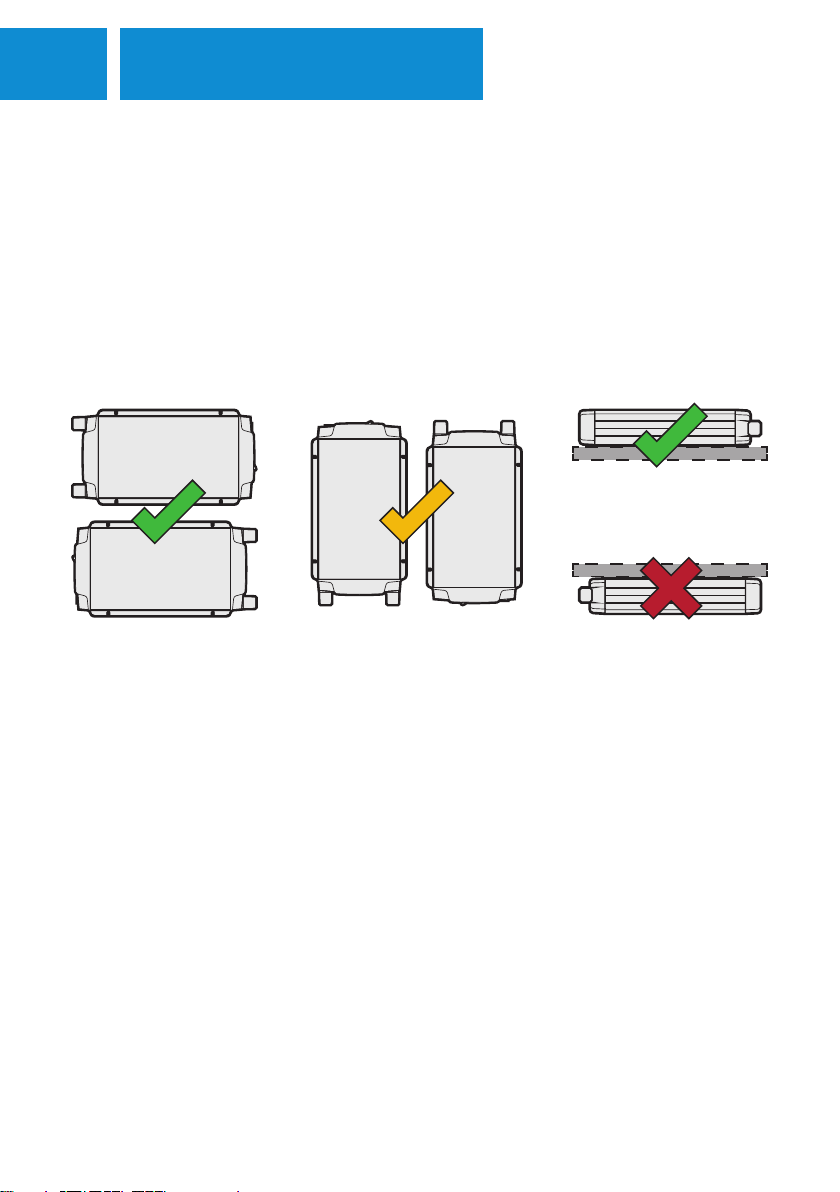
• ORIENTATION - The inverter should ideally be mounted horizontally either on a wall or flat surface with
the base facing downward. You can mount the inverter vertically on a wall, however this orientation is
less ideal due to the possibility of stress on the circuit board. Do not mount the inverter base up on
any surface, as this puts higher stress on the circuit board and risks damaging components.
• DRY - The inverter must be mounted in an area free from water ingress of any kind.
• COOL - For optimal operating conditions, choose a location that stays within the temperature range of
between 0°C and 40°C.
• SAFE - The inverter must be mounted in an area free from fumes and other hazardous substances.
• VENTILATED - Ensure a margin of at least 100mm around the inverter to reduce heat build-up.
• LIMITED DUST - The inverter must be mounted in an area with little to no dust ingress to reduce the
likelihood of dust being drawn in by the fans when in operation.
• ELECTRICALLY SAFE - Ensure the inverter is mounted close to the battery to reduce any significant drop
in voltage. With this in mind, the inverter must not be mounted within 300mm of the battery. A fuse must
be fitted between the inverter and battery on the positive cable, with the fuse fitted close to the battery
end to protect the cable.

8INSTALLATION DC
BATTERY
BATTERY
4
4
0A
0A
FUSE
FUSE
Before installing your inverter, consult your battery’s user guide to make sure they are:
• Operating as a dedicated 12V battery.
• Of either an SLA, AGM, Gel, Calcium, or LiFePO4 chemistry.
• In good working order, free from any fault or damage.
Additionally, the batteries should be equipped with a high enough continuous discharge rate to cater to the
highest draw of the inverter. The guide below details the maximum current draw for each inverter.
The inverters are also able to be powered by systems running with batteries connected in parallel. For some
batteries, the maximum continuous discharge rate will be increased when paralleled with a compatible unit.
Before wiring the inverter to a parallel setup, consult your battery’s user manual to ensure that it matches the
above criteria. Below is a guide outlining how the inverter should be wired to a parallel system.
BATTERY PREPARATION
HKPINVAC1000 HKPINVAC2000 HKPINVAC3000
MAX CURRENT DRAW 94A 187 A 2 81 A
Shunt
Mega-fuse
9INSTALLATION DC
CABLE & FUSE GUIDE
440A0AFUSEFUSE
Positive cable length
Negative cable length
TOTAL CABLE LENGTH = POSITIVE CABLE LENGTH + NEGATIVE CABLE LENGTH
FUSES MUST BE FITTED CLOSEST TO BATTERY POSITIVE TERMINAL
CABLE LENGTH (COMBINED) HKPINVAC1000 HKPINVAC2000 HKPINVAC3000
0 1M 35mm² (2) 70mm² (2/0) 95mm² (3/0)
1 2M 35mm² (2) 70mm² (2/0) 95mm² (3/0)
2 3M 50mm² (1/0) 95mm² (3/0) 120mm² (4/0)
3 4M 70mm² (2/0) 120mm² (4/0) Not recommended
4 5M 95mm² (3/0) Not recommended
OVER 5M Not recommended
FUSE SIZE HKPINVAC1000 HKPINVAC2000 HKPINVAC3000
MEGA FUSE 150A 250A 350A
CABLE GAUGE mm² (AWG)
Mega-fuse
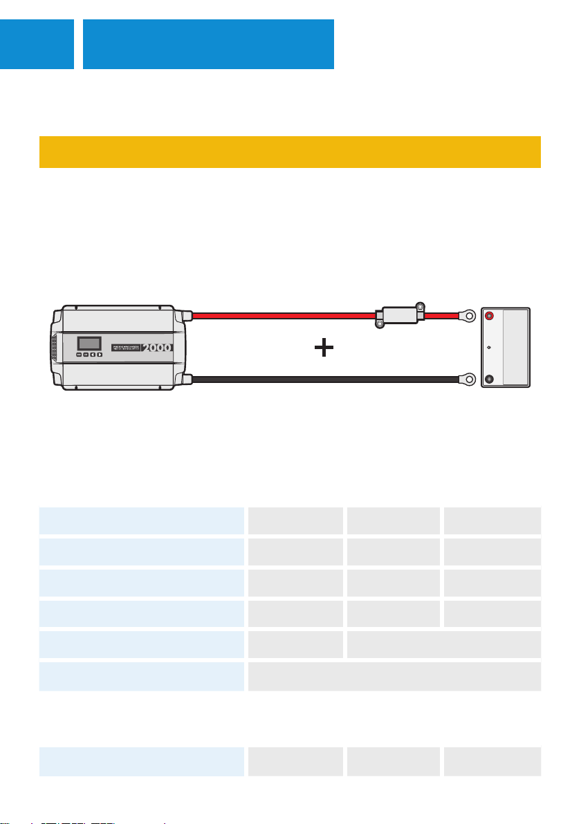
The cable between the inverter and battery must be of a large enough gauge to prevent significant voltage
drop over the length of the cable. Because voltage drop occurs between the battery positive and ground, the
total cable length combined (positive and negative) needs to be considered.
NOTE: The cables should be routed in a way that prevents them from being damaged. Consider cable conduit
or protective tubing to reduce abrasion.
10INSTALLATION DC
INSTALLATION
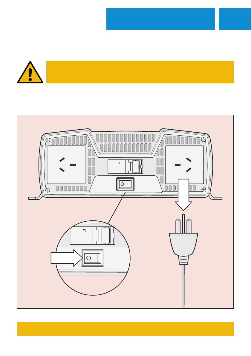
INSTALLATION OF THIS DEVICE MUST BE PERFORMED
BY A LICENCED PROFESSIONAL
Before wiring the inverter into your system, ensure the inverter switch is on the OFF position and nothing is
plugged into the AC outputs.
THIS PROCESS MUST BE COMPLETED BEFORE ANY INSTALLATION

11 INSTALLATION DC
CONNECTING THE BATTERY
CHASSIS GROUNDING
The inverter must be grounded properly before operating. Failure to do so
will increase the risk of damage or injury.
The Inverter’s dedicated grounding point can be found on the mounting
flange of the unit, close to the negative terminal.
Ground the unit using a cable with a minimum of 4mm² copper conductor
by screwing the cable into the inverter’s grounding point. The other end of
the cable should be attached to an appropriate earthing point – this may be
the vehicle frame or the battery’s negative terminal if it has been grounded.
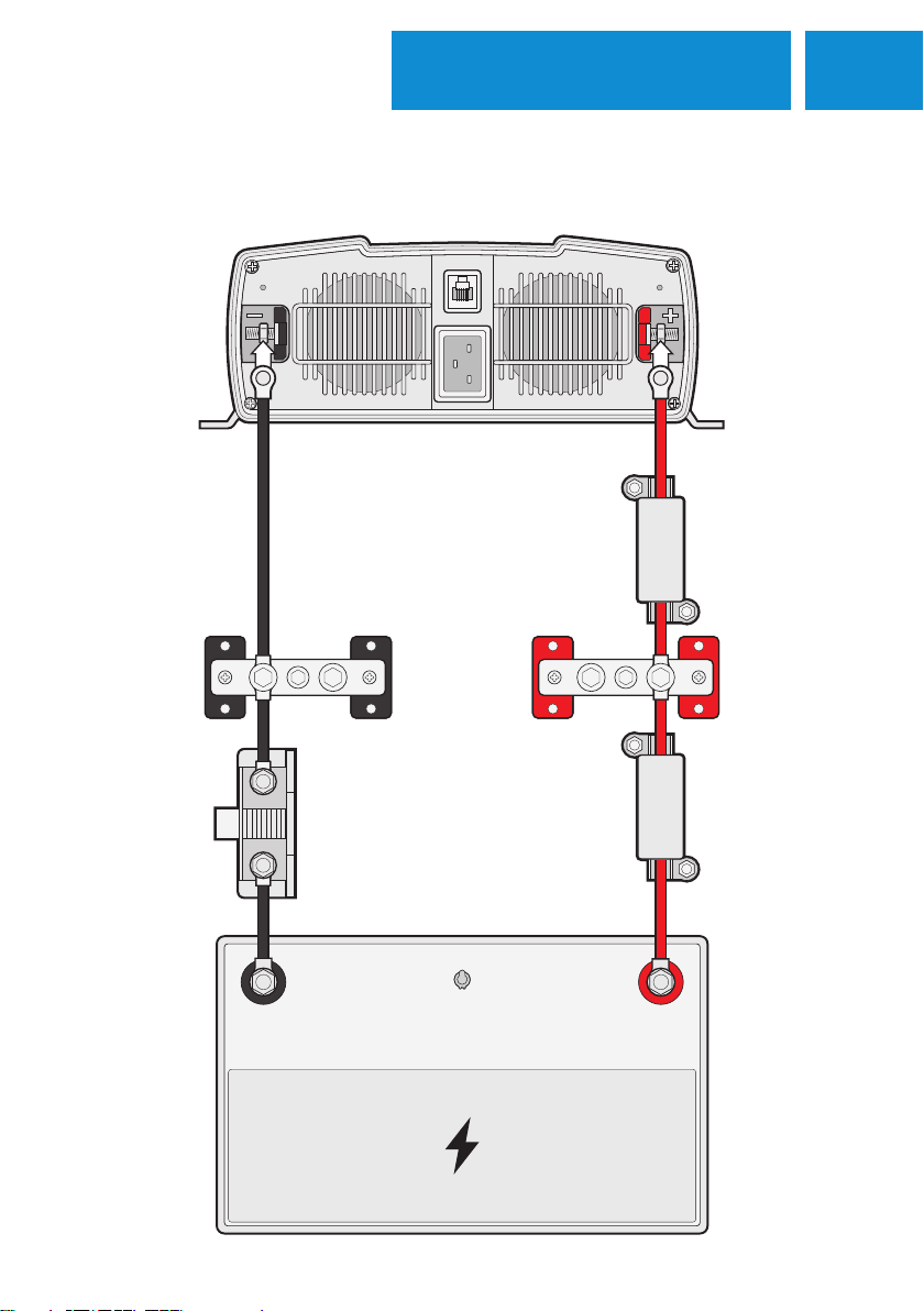
1. Before proceeding, ensure that you have the appropriate-sized cables and fuses outlined earlier in this
manual. Make sure that you’ve also read the power isolation requirements found on page 10.
2. Remove the inverter’s plastic terminal covers by loosening the screws at the top and bottom of the covers.
Thread these covers over the top of the leads you’ll be using to connect to the inverter.
3. Next, remove the nuts and washers from the inverter’s terminals.
4. The positive and negative cables should then be fastened to their respective input terminals. Connect the
positive lead first, by threading the cable eye and washers over the bolt, then fasten it with your nut so it’s
secure. Repeat this process with the negative lead.
5. Now, fasten the inverter terminal covers back onto the inverter.
6. These cables should then be connected to the battery/DC power source. Fasten them first to the positive
terminal, then the negative. Ensure that the positive lead has an appropriately sized fuse placed close to
the battery.
12INSTALLATION DC
BASIC SETUP DIAGRAM
MEGA-FUSE PLACED
TOWARD BATTERY
END OF CABLE
(MANDATORY)
MEGA-FUSE PLACED
TOWARD INVERTER
END OF CABLE
(OPTIONAL)
BUSBARS
FOR WIRING
ACCESSORIES
(OPTIONAL)
BATTERY
MONITOR
SHUNT
(OPTIONAL)
BATTERY
440A0AFUSEFUSE 440A0A
FUSEFUSE
13 INSTALLATION AC
WHAT IS AN AC TRANSFER SWITCH?
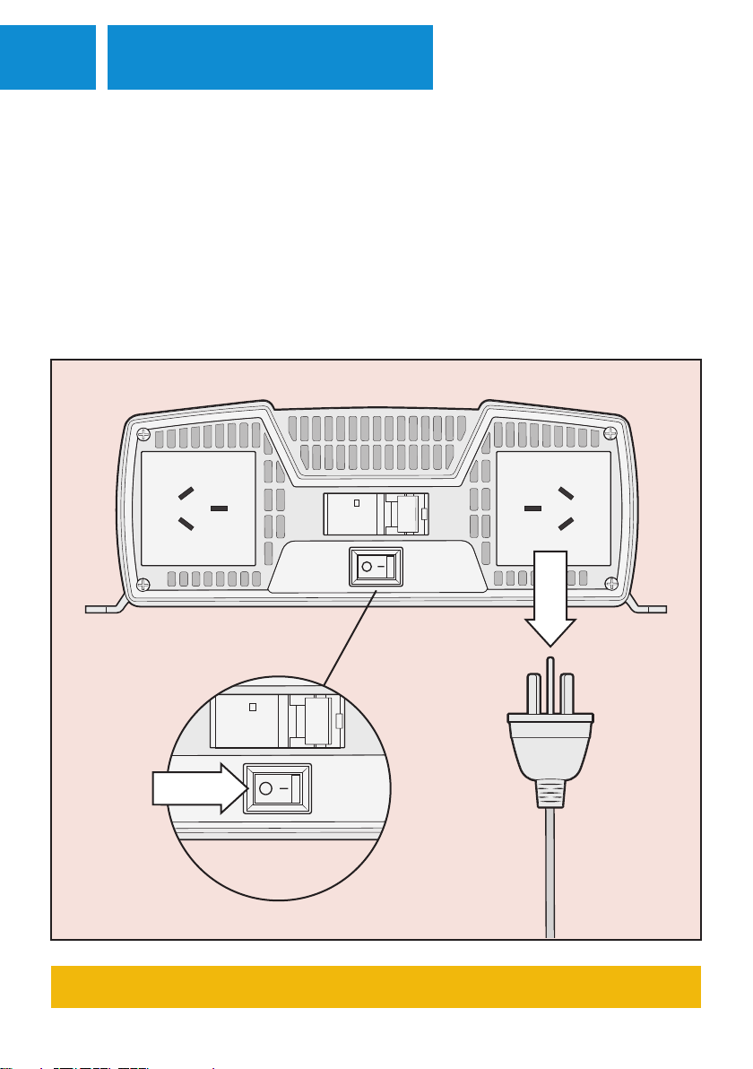
Before wiring the inverter into your system, ensure the inverter switch is on the OFF position and nothing is
plugged into the AC outputs.
THIS PROCESS MUST BE COMPLETED BEFORE ANY INSTALLATION
This function allows the inverter to automatically switch from running via 12V to AC/mains power. Particularly
useful for conserving your batteries, it is used in scenarios when you have decided to run your setup from a
generator or from a powered site at a caravan park. The feature is enabled as soon as it detects an incoming
AC current, switching the inverter from 12V in less than 30 milliseconds.
This section outlines how to wire up the inverter to enable to AC transfer switch function.
14INSTALLATION AC
AC INPUT INSTALLATION
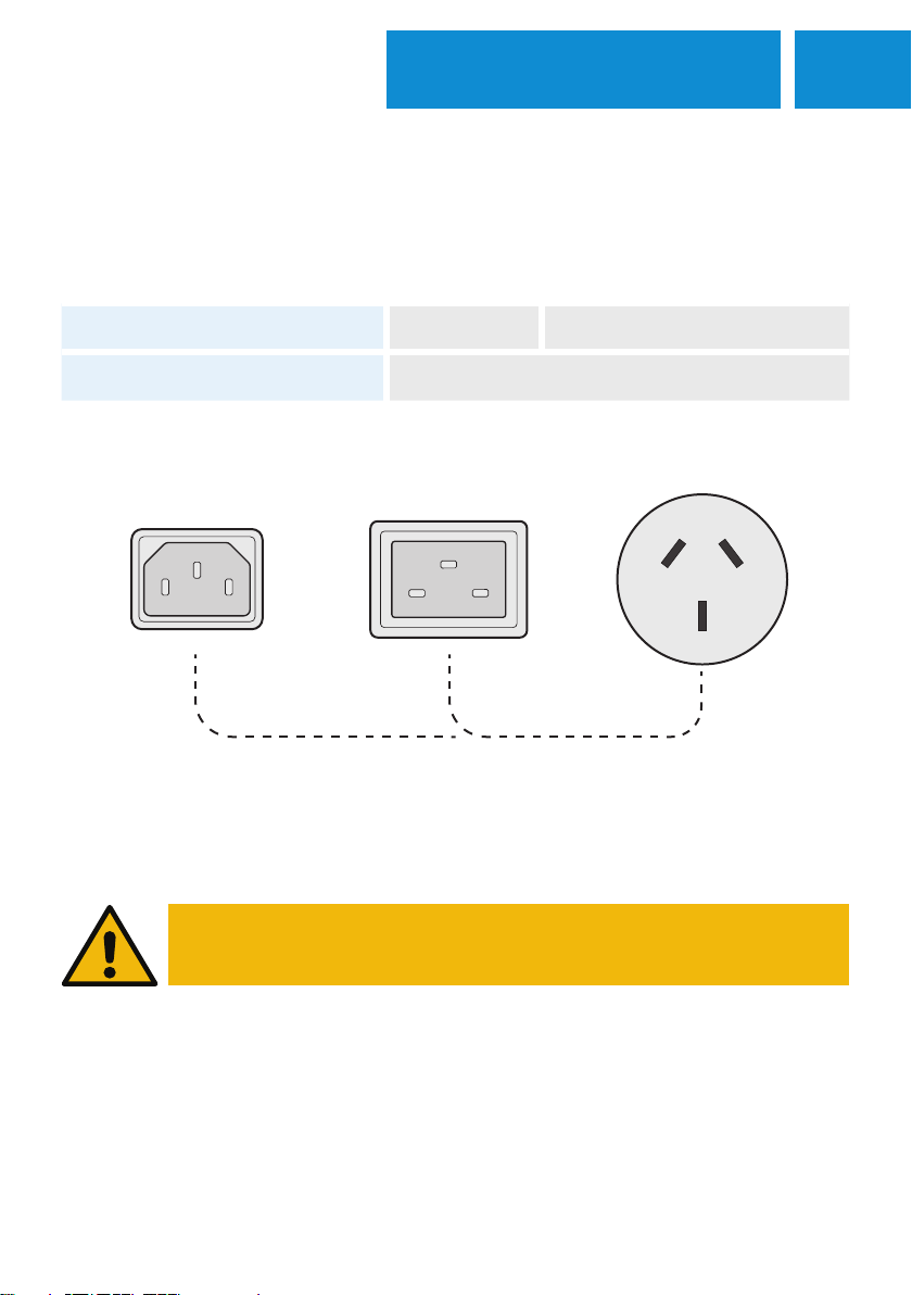
The following cables are required prior to connecting the AC input. Note: These are not included in your kit.
IECC13 IECC19 TYPE I
AC INPUT CABLE HKPINVAC1000 HKPINVAC2000 HKPINVAC3000
INPUT END IEC-C13 IEC-C19
MAINS END TYPE I
SETUPS THAT INCLUDE HARD-WIRED AC PORTS REQUIRE
A LICENCED PROFESSIONAL TO INSTALL THE INVERTER.
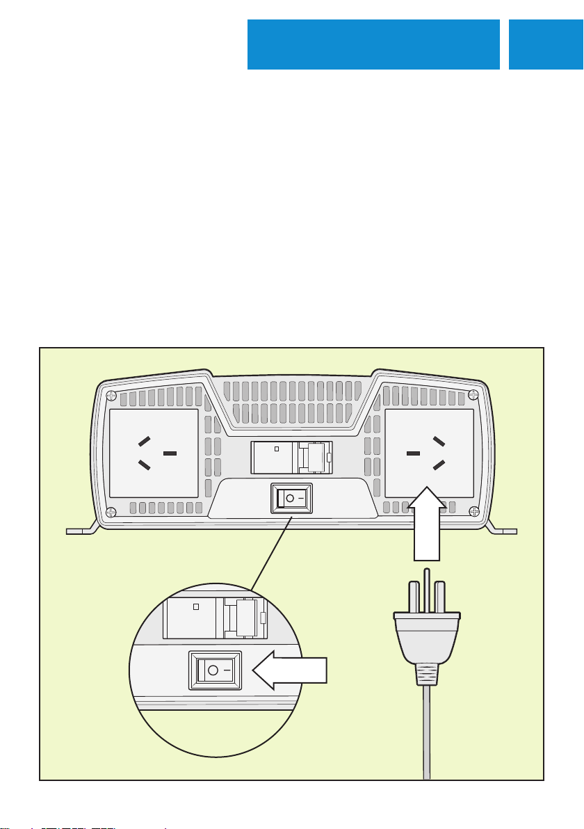
To connect the inverter to AC power simply plug the IEC plug into the inverter’s onboard AC input, then plug
the three-pin plug into an AC socket outlet/power point. The inverter is designed to automatically run off AC
power when available.
15 INSTALLATION REMOTE
REMOTE CONTROL INSTALLATION
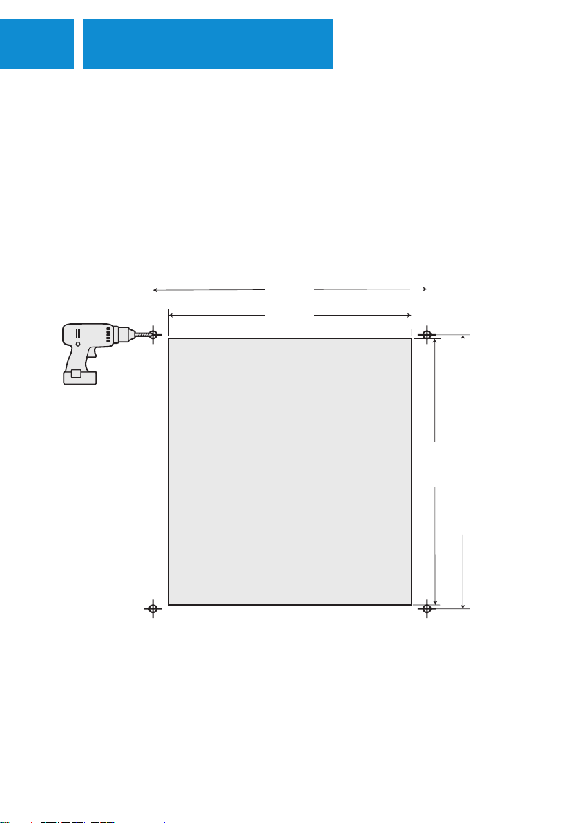
70mm
68mm
70mm
62mm
The remote allows the inverter to be operated from an alternate location. This is ideal in installs where the
inverter may not be easily accessible. The remote is designed to be flush-mounted onto a suitable surface, such
as a canopy wall.
1. Locate a space you would like the inverter remote control to be positioned, preferably an interior space
free from moisture.
2. Consult the below mounting diagram for reference. You can mark the mounting holes and corners of the
cutout with a pin or centre punch.
3. Drill 2mm holes in the marked mounting points (or simply leave the points marked) and cut a hole in the
surface of the mounting location according to the above diagram.
4. Remove the faceplate of the remote by pulling on the small recess along one of the outer edges (varies
depending on model).
5. Place the remote into the hole that you cut and use M3 screws (self-tapping screws if the holes were not
pre-drilled) to fasten the remote in place.
6. Re-attach the remote faceplate and plug the RJ11 connector into the corresponding port on the inverter.
Cutout
16OPERATION
OPERATING THE INVERTER
After wiring up the input side, the inverter is now ready to run your 240V appliances. Before operating the
inverter, make sure that the appliance/s you intend on running have a total/cumulative wattage that is below
the inverter’s rated wattage. Below outlines the process of running your appliances off the inverter.
1. If running the inverter from 12V, make sure the battery has enough charge to be able to run it. If running
from AC input, make sure it has been connected securely.
2. Make sure the RCD switch is in the correct position. Do not operate if it has been tripped - consult
an electrician.
3. Plug the appliance into the unit’s AC output socket.
4. Turn the inverter on, and make sure the mains AC supply is on if you are running the inverter that way.
5. Switch the appliance on.
17 OPERATION
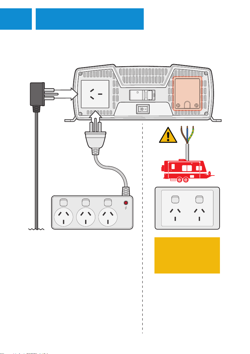
AC OUTPUT OVERVIEW
100W + 200W + 500W = 800W power draw
STANDARD AC INPUT DANGER: ELECTRICAL SHOCK
HAZARD. ONLY LICENCED
ELECTRICIANS ARE PERMITTED
TO CONNECT LOADS TO THE
HARD WIRE TERMINAL BLOCK.
HKPINVAC3000
Each inverter contains standard Type I 240V sockets
for appliances.
You can plug the appliance directly into the inverter,
or use a powerboard to power multiple appliances
at the same time. Please note that you can only plug
multiple devices in with wattages that are below the
respective inverter's capability (example below). The 3000W inverter model
is equipped with a hard wire
terminal block for use within a
caravan or other permanent
fitment situation.
This manual suits for next models
2
Table of contents
Other HARDKORR Inverter manuals


