Terrasmart TerraGlide User manual

This system conforms to UL Standard 2703 Edition One.
© Copyright 2022, Terrasmart, Inc. All rights reserved. | TerraGlide Portrait Installation Manual | Page 1 of 52
Proprietary and confidential. The information contained in this document is the sole property of Terrasmart.
Any reproduction in part or as a whole without written permission of Terrasmart is prohibited
www.terrasmart.com
271167
TerraGlide Portrait Installation Manual
REV 10: November 2022

This system conforms to UL Standard 2703 Edition One.
© Copyright 2022, Terrasmart, Inc. All rights reserved. | TerraGlide Portrait Installation Manual | Page 2 of 52
Proprietary and confidential. The information contained in this document is the sole property of Terrasmart.
Any reproduction in part or as a whole without written permission of Terrasmart is prohibited
www.terrasmart.com
271167
Table of Contents
1General Document Overview......................................................................................................................3
1.1 Introduction ..................................................................................................................................3
1.2 Installer Responsibility Checklist...................................................................................................3
1.3 Notice............................................................................................................................................4
1.4 Safety Symbols and Signal Words.................................................................................................4
1.5 Notes.............................................................................................................................................5
1.6 Common Terms.............................................................................................................................5
2TerraGlide Portrait Details Pre-Installation.................................................................................................6
2.1 Steel Members and Bracket Components Overview ....................................................................6
2.2 TerraGlide Portrait Hardware Components Overview..................................................................7
2.3 TerraGlide Portrait Torque Values..............................................................................................10
2.4 Required Tools for TerraGlide Landscape Installation................................................................11
2.5 Component On-Site Storage Prior to Installation .......................................................................12
3TerraGlide Portrait Mounting System Installation ....................................................................................13
3.1 Installation Warning, Caution and Notice Statements ...............................................................13
3.2 Workflow Overview for TerraGlide Portrait Assembly ...............................................................14
3.3 Specific Installation Steps ...........................................................................................................15
3.4 Bonding and Grounding Requirements ......................................................................................34
3.5 PV Module Bonding Section........................................................................................................37
Appendix 1 Terrasmart, Inc. UL 2703 Approved PV Module Bonding List………………………………………………….45
Appendix 2 Jinko Solar High Loading PV Module Mounting With 6 Connection Points ................................51
Appendix 3 Document Revision History Log..................................................................................................52

This system conforms to UL Standard 2703 Edition One.
© Copyright 2022, Terrasmart, Inc. All rights reserved. | TerraGlide Portrait Installation Manual | Page 3 of 52
Proprietary and confidential. The information contained in this document is the sole property of Terrasmart.
Any reproduction in part or as a whole without written permission of Terrasmart is prohibited
www.terrasmart.com
271167
1General Document Overview
1.1 Introduction
The TerraGlide Portrait Ground Mount Solar Racking System (TGP) is specifically designed in conjunction with Terrasmart
ground screw foundations. Terrasmart custom engineers each racking system based upon site-specific loading
requirements, soil and terrain conditions, and other client specifications.
The TGP racking system is designed to meet or exceed applicable ASCE, IBC, NEC, and UL standards. Modules are to be
installed in a Portrait orientation with a maximum rack size of 2X12. Because each racking system is subjected to different
loads and/or module specifications, structural and mechanical components may vary slightly from one rack to another.
This document outlines the installation of a generic racking system and should be interpreted as such when installing
racking systems designed specifically for a project. Signed and sealed project specific construction plans take precedence
over this manual. For details regarding module compatibility, refer to section 3.5 and Appendix 1. Failure to comply with
installer responsibilities as outlined below, may void the product warranty, cause legal implications, and/or make it
impossible for Terrasmart to replace defective, damaged, or missing parts. Please contact Terrasmart project manager
with any questions, comments, complaints, or suggestions.
1.2 Installer Responsibility Checklist
1. Comply with all applicable local, state, and national building codes and laws, including any that supersede this
manual.
2. Procure all required permits prior to installation and ensure that component design parameters are not ex-
ceeded.
3. Provide appropriate method of direct-to-earth grounding in accordance with the latest edition of the National
Electric Code (NEC), including NEC 250: Grounding and Bonding and NEC 690: Solar Photovoltaic Systems. See
section 3.4 for details.
4. Use only parts supplied by Terrasmart specifically designed for use with the TGP.
5. Ensure PV modules are physically compatible with the dimensions of the TGP prior to installation. PV modules
vary between brands, models, and dates of manufacture; each TGP Rack is custom designed to accommodate
dimensions of the PV module as specified by the client.
6. Inspect the quality of the ground screw installation and that the foundations are within acceptable tolerances,
as defined in the Approved Project Specific Engineering/Construction Plans.
7. Upon delivery of materials, inspect all packages and refuse any that contain damaged parts. Take an inventory
of all delivered parts to ensure that all required parts are in your possession.
8. Follow the steps outlined in this installation manual and notify Terrasmart within 48 hours of delivery of any
missing or defective parts or any other concern with regards to the installation process, including conflicts
between this installation manual and codes, regulations, laws and/or other documentation.
This system conforms to UL Standard 2703 Edition One.
© Copyright 2022, Terrasmart, Inc. All rights reserved. | TerraGlide Portrait Installation Manual | Page 4 of 52
Proprietary and confidential. The information contained in this document is the sole property of Terrasmart.
Any reproduction in part or as a whole without written permission of Terrasmart is prohibited
www.terrasmart.com
271167
1.3 Notice
Changes to certain components are common as Terrasmart continuously strives to improve its products. All products
within the same model classification remain functionally equivalent and compatible with one another, even though there
may be slight differences. Any modifications to the TerraGlide racking system requires Terrasmart’s prior written approval.
Terrasmart reserves the right to make changes to design and specifications applicable to any TGP Mounting System
component at any time without notice. Accordingly, the owner is responsible for verifying that data sheets are current
before placing orders or finalizing system permitting and/or design. Neither Terrasmart nor its affiliates assume any
responsibility for use of information furnished by Terrasmart or its affiliates, nor for any infringements of patents or other
rights of third parties that may result from the use of such information. No license is granted by implication or otherwise
under any patent or patent rights of Terrasmart or its affiliates.
For information regarding Terrasmart and its products, please visit www.Terrasmart.com. For technical support, please
contact Terrasmart project manager.
1.4 Safety Symbols and Signal Words
Indicates a safety hazard or unsafe practice.
Indicates an electrical shock hazard.
DANGER Indicates a hazardous situation that, if not avoided, will result in death or serious injury.
WARNING Indicates a hazardous situation that, if not avoided, could result in death or serious injury.
CAUTION Indicates a hazardous situation that, if not avoided, could result in injury.
NOTICE Indicates information considered important, but not hazard-related.

This system conforms to UL Standard 2703 Edition One.
© Copyright 2022, Terrasmart, Inc. All rights reserved. | TerraGlide Portrait Installation Manual | Page 5 of 52
Proprietary and confidential. The information contained in this document is the sole property of Terrasmart.
Any reproduction in part or as a whole without written permission of Terrasmart is prohibited
www.terrasmart.com
271167
1.5 Notes
System Safety Information:
Owner, owner’s agents, general contractors, maintenance personal and/or anyone in contact with this
racking system should read and understand all instructions and safety information before attempting to
install, operate and/or maintain this system. Failure to comply with instructions and safety information
may result in death, serious injury, or damage to the product.
•Installation and Service is to be performed only by qualified personnel.
•Installation must be completed according to the project site drawings.
•Proper personal protective equipment (PPE) shall be used when working with this system.
oElectrically rated PPE should be worn when working on modules or other electrical system
components.
oCut-resistant gloves should be worn when working on non-electrically-interconnected mod-
ules or components.
oSafety glasses should always be worn when working with this system.
DANGER To avoid death or serious injury due to electric shock:
•Disconnect incoming power sources before servicing.
•More than one disconnect switch may be required to de-energize the equipment.
•Follow lockout –tagout procedures before servicing.
•Avoid working on system in rain or standing water.
Proper Installation and Maintenance:
The TerraGlide Portrait Mounting System must be installed, operated, and maintained as specified in this manual and the
TerraGlide O&M manual. If not, then personal safety and product reliability may be compromised. Inspections of all
components should be performed yearly to ensure there are no loose components, fasteners or corrosion. Any affected
components need to be immediately replaced.
1.6 Common Terms
Colloquial terms and abbreviations
Proper names and explanations
Cable
Wire, Wiring, PV Double Insulated Wire, Seismic Bracing, Gripple Kit
Post, Leg
Vertical Support (not foundation), North Post, South Post
Beam
Cee Purlin
Panel
PV Module
Frame Assembly
Assembled Rafter, Lateral Brace, North Post, and South Post
Rafter, Strut
Proprietary Hat Section
Ground Screw
Ground Screw Foundation
Nuts, Bolts
Fasteners, Hardware
ASTM
American Society for Testing and Materials
ANSI
American National Standards Institute
SAE
Society of Automotive Engineers
DIN
German Institute for Standardization
SEMS
Screw and Integrated or Encapsulated Washer Assemblies
Loose Fit
Nut/Bolt Threaded Together. Allows Connection to Rotate
Snug
Nut/Bolt Finger Tight (or with Tool) Not Fully Torqued
Torqued
Nut/Bolt Fully Torqued Per Specification
Table 1.6.1. List of items that may be found in site design drawings and their corresponding correct definitions or equivalents used in this Installation Guide.

This system conforms to UL Standard 2703 Edition One.
© Copyright 2022, Terrasmart, Inc. All rights reserved. | TerraGlide Portrait Installation Manual | Page 6 of 52
Proprietary and confidential. The information contained in this document is the sole property of Terrasmart.
Any reproduction in part or as a whole without written permission of Terrasmart is prohibited
www.terrasmart.com
271167
2TerraGlide Portrait Details Pre-Installation
2.1 Steel Members and Bracket Components Overview
DESCRIPTION
LOCATION USED
Ground Screw
FOUNDATION
Leg Post
FRAME ASSEMBLY
Internal Diagonal Lateral Brace
Internal Horizontal Lateral Brace (upper and/or lower)
FRAME ASSEMBLY
External Diagonal Lateral Brace
External Upper Horizontal Lateral Brace
FRAME ASSEMBLY
TPF External Lower Horizontal Lateral Brace
TPF External Diagonal Lateral Brace (When Horizonal Brace is required)
FRAME ASSEMBLY
North South Rafter
FRAME ASSEMBLY

This system conforms to UL Standard 2703 Edition One.
© Copyright 2022, Terrasmart, Inc. All rights reserved. | TerraGlide Portrait Installation Manual | Page 7 of 52
Proprietary and confidential. The information contained in this document is the sole property of Terrasmart.
Any reproduction in part or as a whole without written permission of Terrasmart is prohibited
www.terrasmart.com
271167
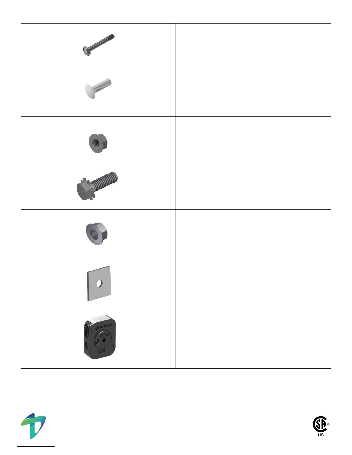
2.2 TerraGlide Portrait Hardware Components Overview
DESCRIPTION
LOCATION USED
M16 x2x25 Hex Bolt
GROUND SCREW SET BOLTS
1/2”-13 x 1-1/2” Carriage Bolt
SLOPE BRACKET FASTENER
FASTENS CEE PURLIN AND RAFTER TO SLOPE BRACKET
1/2”-13 x 4” Serrated Flange Hex Bolt
FRAME ASSEMBLY FASTENER
FASTENS RAFTER TO POSTS
1/2”-13 Serrated Flange Hex Nut
FRAME ASSEMBLY FASTENER
FOR USE WITH
1/2”-13 X 1-1/2” SERRATED FLANGE HEXBOLT AND
1/2” -13 x 4” SERRATED FLANGE HEX BOLT
Cee Purlin
EAST-WEST BEAM
AND
MODULE MOUNTING RAIL
Slope Bracket
FRAME ASSEMBLY TO
CEE PURLIN CONNECTION
This system conforms to UL Standard 2703 Edition One.
© Copyright 2022, Terrasmart, Inc. All rights reserved. | TerraGlide Portrait Installation Manual | Page 8 of 52
Proprietary and confidential. The information contained in this document is the sole property of Terrasmart.
Any reproduction in part or as a whole without written permission of Terrasmart is prohibited
www.terrasmart.com
271167
3/8”-16 x 3” Carriage Bolt
FRAME ASSEMBLY FASTENER
FASTENS LATERAL BRACE INTERNAL TO
LATERAL BRACE EXTERNAL
3/8”-16 x 1-1/2” Carriage Bolt
FRAME ASSEMBLY FASTENER
FASTENS BRACE CLAMPS
3/8”- 16 Serrated Flange Nut
FRAME ASSEMBLY FASTENER
FOR USE WITH
3/8”-16 X 3” HEX BOLT AND
3/8”-16 X 1-1/2" CARRIAGE BOLT
M6-1.00 x 20mm OR M8-1.25 x 20mm SEMS Hex Bolt
UNDERMOUNT MODULE FASTENER
DIAMETER VARIES PER MODULE SPECIFICATION
M6-1.00 OR M8-1.25 Serrated Flange Nut
UNDERMOUNT MODULE FASTENER
DIAMETER VARIES PER MODULE SPECIFICATION
Washer Plate
FRAME ASSEMBLY
FASTENS TO RAFTER AND POSTS
Gripple Dynamic
SEISMIC BRACING LOCK

This system conforms to UL Standard 2703 Edition One.
© Copyright 2022, Terrasmart, Inc. All rights reserved. | TerraGlide Portrait Installation Manual | Page 9 of 52
Proprietary and confidential. The information contained in this document is the sole property of Terrasmart.
Any reproduction in part or as a whole without written permission of Terrasmart is prohibited
www.terrasmart.com
271167
Wire Rope
SEISMIC BRACING CONNECTOR
LENGTH VARIES BY TABLE SIZE
Brace Clamp Half
FRAME ASSEMBLY
5/8”-11 x 6” Serrated Flange Hex Bolt
FRAME ASSEMBLY
* THROUGH BOLT FOR GROUND SCREW
5/8”- 11 Serrated Flange Nut
FRAME ASSEMBLY
* THROUGH BOLT FASTENER
*Note: The through bolt is only needed if the leg install process damages the set bolts or welded nuts on ground screw.
Hole will be drilled and through bolt will be used.
NOTICE
Reference the project construction drawings for a complete part list for each specific project site.
Specific projects may have additional or alternate component requirements.

This system conforms to UL Standard 2703 Edition One.
© Copyright 2022, Terrasmart, Inc. All rights reserved. | TerraGlide Portrait Installation Manual | Page 10 of 52
Proprietary and confidential. The information contained in this document is the sole property of Terrasmart.
Any reproduction in part or as a whole without written permission of Terrasmart is prohibited
www.terrasmart.com
271167
2.3 TerraGlide Portrait Torque Values
Hardware Nominal Diameter
& Thread Pitch
Bolt Location
Material/Grade
Nominal Torque
(ft-lbs)
Torque Range
(ft-lbs)
M6-1.00
Module to Purlin
Stainless Steel
(304/316)
7
6 - 9Note 3
M8- 1.25
11
8 –18.5Note 3
1/2”x 1-1/2” Carriage Bolt
Rafter to Slope
Bracket
Carbon Steel
SAE Grade 5
64
45 - 80
Purlin to Slope
Bracket
1/2”-x 4” Serrated Flange
Hex Bolt
Leg to Rafter
64
45 –80 Note 1
Brace to Rafter
30
20 –80 Note 2
3/8” x 1-1/2” Carriage Bolt
Lateral Brace
Clamp Connections
Carbon Steel
SAE Grade 5
26
23 - 30
3/8” x 3” Carriage Bolt
Internal to External
Brace Connection
Carbon Steel
SAE Grade 5
26
23 - 30
M16-2.00 Set Bolt
Ground Screw bolt
to Leg Connection
Carbon Steel
Class 45H
Bottomed out –bolt head touching ground
screw weld nut.
Table 2.3.1 - Torque values for listed hardware
NOTICE
Due to variations in tools, environmental conditions, and plastic deformation over time; quality
control checks performed after 48 hours may observe a reduction in nominal torque, up to a 30%
reduction is allowable. No torque adjustment is required if within the specified range.
Table 2.3.1; Note 1 - Leg to Rafter Connection; The min/max torque range is 45 –80 ft-lbs. The
nominal torque is 64 ft-lbs as stated in the table above. For torques over > 64 ft-lbs, it is acceptable
to have visual loading deformation of the leg to rafter joint connection.
Table 2.3.1; Note 2 - Brace to Rafter Connection; The min/max torque range is 20 –80 ft-lbs. The
nominal torque is 30 ft-lbs as stated in the table above table. It is acceptable to have visual loading
deformation of the brace to rafter joint connection.
If bolt installation results in continual deformation of the Hat Rafter without achieving full torque,
then it is acceptable to achieve torque by driving the nut until it reaches the end of the threaded
portion of the bolt.
Table 2.3.1; Note 3 –Refer to section 3.5, PV Module Bonding, and Appendix 1, Terrasmart, Inc. UL
2703 Approved PV Module Bonding List, for additional information on specific PV module bonding
method torque values.

This system conforms to UL Standard 2703 Edition One.
© Copyright 2022, Terrasmart, Inc. All rights reserved. | TerraGlide Portrait Installation Manual | Page 11 of 52
Proprietary and confidential. The information contained in this document is the sole property of Terrasmart.
Any reproduction in part or as a whole without written permission of Terrasmart is prohibited
www.terrasmart.com
271167
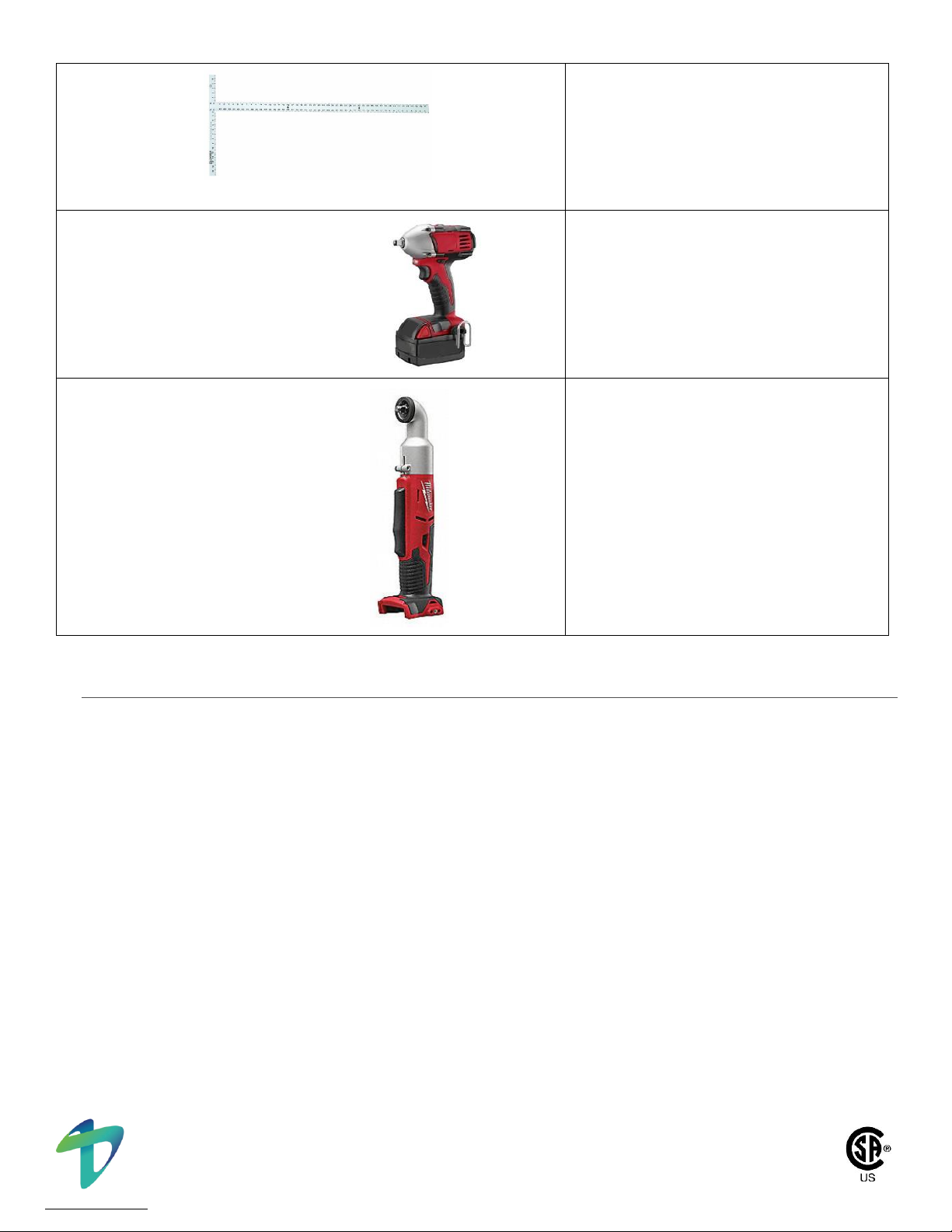
2.4 Required Tools for TerraGlide Landscape Installation
Below is a table of tools required to install the TGP PV module racking system.
TOOL DESCRIPTION
PURPOSE
Torque Wrench
Torque fasteners to specification in
accordance with section 2.3
Sockets
7/16” Socket for Seismic Cable Saddles
9/16” Socket for 3/8” Hardware
3/4” Socket for 1/2” Hardware
10mm Socket for M6 Hardware
13mm Socket for M8 Hardware
*Deep Sockets Recommended for above*
15/16” Shallow Well Socket for M16 Set Bolt
Socket Extension
3” Min Socket Extension. Install Slope
Bracket to Hat Rafter
Digital Level
Verify tilt angle and plumbness of steel
members
String Line
Used for alignment
(Optional)
Cold Galvanizing Compound
(minimum 93% Zinc)
Repair exposed steel after installation
This system conforms to UL Standard 2703 Edition One.
© Copyright 2022, Terrasmart, Inc. All rights reserved. | TerraGlide Portrait Installation Manual | Page 12 of 52
Proprietary and confidential. The information contained in this document is the sole property of Terrasmart.
Any reproduction in part or as a whole without written permission of Terrasmart is prohibited
www.terrasmart.com
271167
Racking Alignment Tool, 48" Square, or Jig
Align module mounting purlins
3/8" and 1/2" Cordless Impact
To snug all hardware/fasteners
3/8” Cordless 90 Degree Impact
To snug module hardware/fasteners
2.5 Component On-Site Storage Prior to Installation
The following items are to be stored indoors or covered to prevent contact with water and snow:
•Fasteners and hardware
•Any packaging that could deteriorate
The material described below may be stored outdoors, so long as the storage area is not at risk of flooding, water
submersion or snow coverage. However, it is required to cover this material and provide proper dunnage so that material
is not in direct contact with ground. Additionally, if the material is stored outside under coverage, the coverage must
provide proper air flow thus not capturing moisture. The material described in this section is as follows:
•Posts
•Purlins
•Rafters
•Brackets
If components are to be stored off site, then indoor storage is recommended.

This system conforms to UL Standard 2703 Edition One.
© Copyright 2022, Terrasmart, Inc. All rights reserved. | TerraGlide Portrait Installation Manual | Page 13 of 52
Proprietary and confidential. The information contained in this document is the sole property of Terrasmart.
Any reproduction in part or as a whole without written permission of Terrasmart is prohibited
www.terrasmart.com
271167
3TerraGlide Portrait Mounting System Installation
3.1 Installation Warning, Caution and Notice Statements
DANGER Wear electrically rated PPE when working on interconnected modules or other electrical
system components.
WARNING Wear appropriate hard hats and safety glasses (ANSI Z87.1-2003) and cut-resistant gloves
during installation of TerraGlide Portrait Mounting System.
CAUTION Installation is to be performed only by qualified personnel.
CAUTION DO NOT use bolts that have been previously tightened or pre-stressed bolts that are
structurally compromised as they may not retain their strength if recycled.
CAUTION Edges of cee purlins may be sharp, wear cut-resistant gloves at all times when handling and
installing these items.
NOTICE
All TGP Mounting System bolting torque specifications as detailed in this manual must be followed.
Usage of the right tool to complete torque is needed. If battery operated devices are used, efforts
need to be made to ensure a calibrated torque wrench is used to complete tightening process.
NOTICE
All bolts shall be marked with an appropriate marker to indicate proper torque was applied.
NOTICE
No holes shall be added to structural components without prior analysis and approval by Terrasmart,
except for holes necessary for UL467 and UL2703 bonding devices.
NOTICE
A process shall be established with regards to tools and methods to achieve specified torque consist-
ently across the site. For example, a recommended process may involve verifying torque setting with
all applicable tools prior to use in installation and re-verifying every month thereafter.
NOTICE
This racking system may be used to ground and/or mount a PV module complying with UL 1703 only
when the specific module has been evaluated for grounding and/or mounting in compliance with the
included instructions.
This system conforms to UL Standard 2703 Edition One.
© Copyright 2022, Terrasmart, Inc. All rights reserved. | TerraGlide Portrait Installation Manual | Page 14 of 52
Proprietary and confidential. The information contained in this document is the sole property of Terrasmart.
Any reproduction in part or as a whole without written permission of Terrasmart is prohibited
www.terrasmart.com
271167
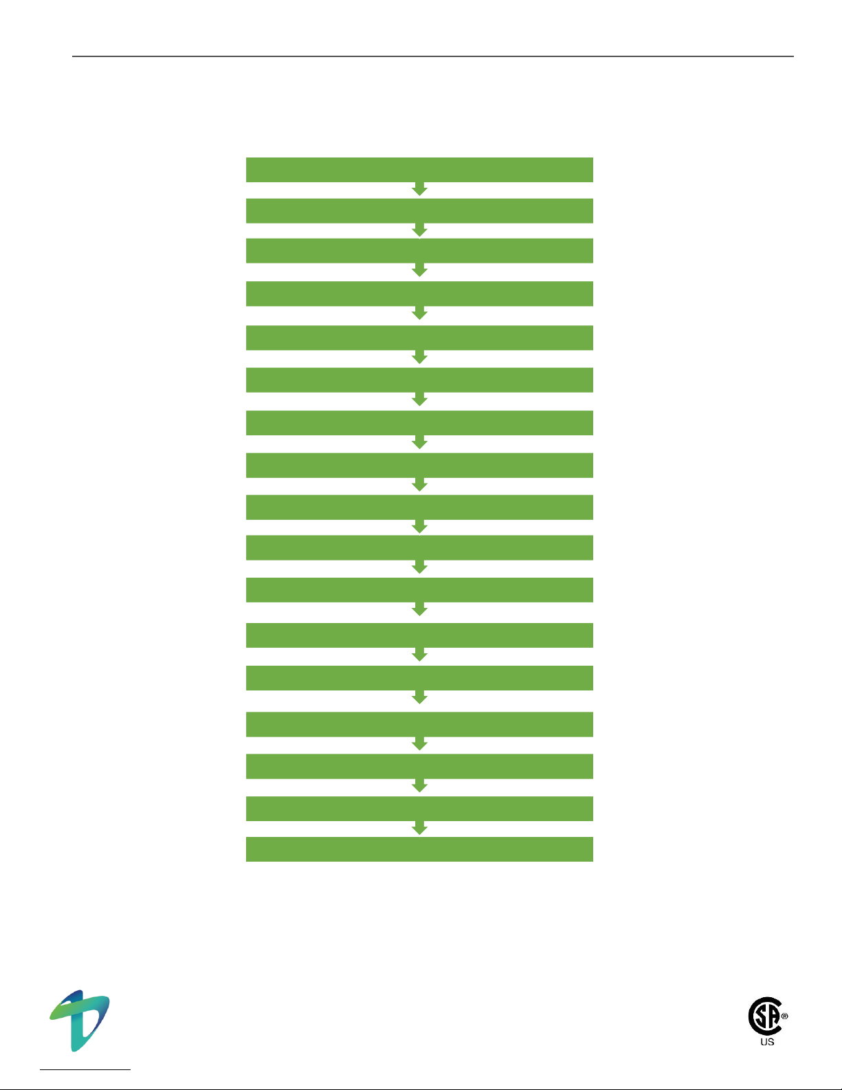
3.2 Workflow Overview for TerraGlide Portrait Assembly
The sequence below provides a suggested workflow guide for assembly of the TerraGlide Portrait Mounting System. This
is one option and other sequences may exist.
Figure 3.2.1 - Suggested workflow for the TerraGlide Portrait Mounting System installation
17. QUALITY CONTROL
16. TORQUE ALL FASTNERS
15. VERIFY TOLERANCES AND ALIGNMENTS
14. INSTALL CROSS BRACES
13. INSTALL PV MODULES
12. ALIGN ADJACENT RACKS
11. ADJUST AND TORQUE SLOPE BRACKETS
10. SQUARE PURLINS
9. FEATHER PURLINS
8. INSTALL CEE PURLINS
7. INSTALL LATERAL BRACES
6. INSTALL RAFTER
5. SET POST HEIGHT
4. DISTRIBUTE NORTH AND SOUTH POSTS
3. PREASSEMBLE/DISTRIBUTE MATERIALS
2. CHECK GROUND SCREWS
1. RECEIVE MATERIALS/STAGING
This system conforms to UL Standard 2703 Edition One.
© Copyright 2022, Terrasmart, Inc. All rights reserved. | TerraGlide Portrait Installation Manual | Page 15 of 52
Proprietary and confidential. The information contained in this document is the sole property of Terrasmart.
Any reproduction in part or as a whole without written permission of Terrasmart is prohibited
www.terrasmart.com
271167
3.3 Specific Installation Steps
The TerraGlide Portrait Mounting System installation should be coordinated with site-specific structural drawings and the
trenching for underground cables.
STEP 1: Receive Materials/Staging
Unload material from trucks and place in designated laydown area. Take inventory of all parts as they are received and
notify Terrasmart immediately if any discrepancies are identified.
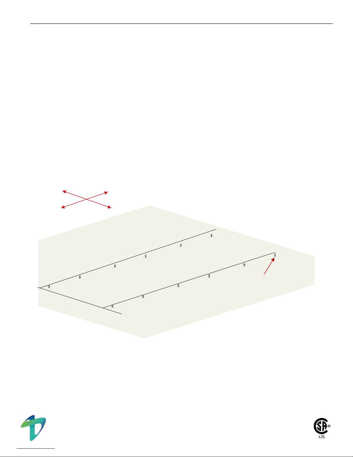
STEP 2: Check Ground Screws
Ground Screws are installed by Terrasmart Construction. Ground Screw location guidance is provided by the TGP
Construction Drawings. Prior to rack installation, check to ensure that Ground Screws are installed within tolerance as
defined in the signed and sealed project specific construction plans and in alignment East to West and North to South as
shown in Figure 3.3.1.
Figure 3.3.1 - Depiction of an Array Row of Ground Screws Installed
N
W
E
S
Installed Ground
Screw
This system conforms to UL Standard 2703 Edition One.
© Copyright 2022, Terrasmart, Inc. All rights reserved. | TerraGlide Portrait Installation Manual | Page 16 of 52
Proprietary and confidential. The information contained in this document is the sole property of Terrasmart.
Any reproduction in part or as a whole without written permission of Terrasmart is prohibited
www.terrasmart.com
271167
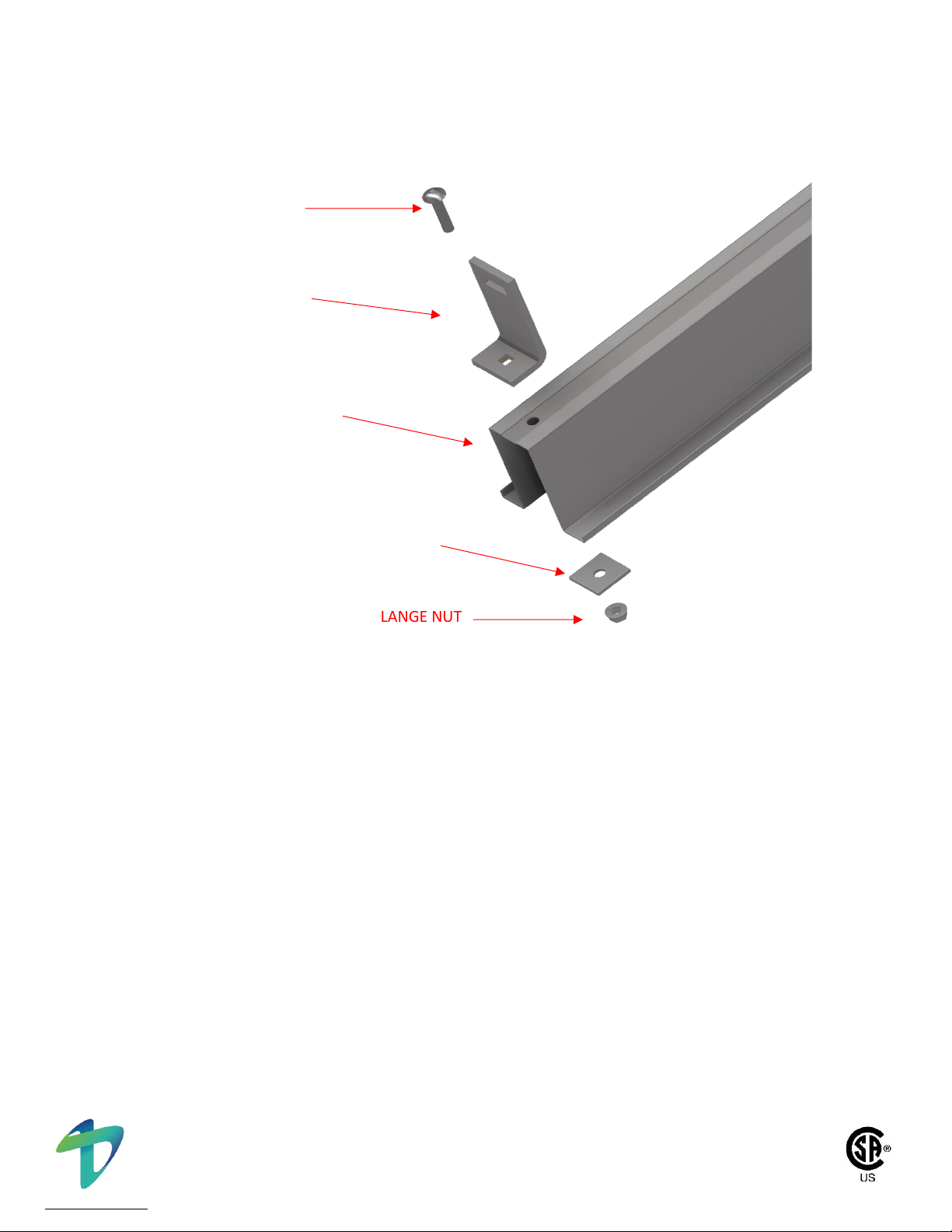
STEP 3: Preassembly/Distribute Materials
Preassembly of Rafter may occur at a centralized station or at each rack. Preassemble Slope Brackets on the rafter as
shown in Figure 3.3.2. Leave bolt loose and distribute materials to the field. Final bolt torque will be performed in Step
11: Adjust and Torque Slope Brackets.
Figure 3.3.2 - Depiction of Slope Bracket to Rafter Assembly
STEP 4: Distribute North and South Posts
Identify the North and South Ground Screw within a rack or Array Row. Place the North Post (typically the longer of the
two posts) next to the North Ground Screw and the South Post (typically the shorter of the two posts) next to the South
Ground Screw.
1/2” - 13 SERRATED FLANGE NUT
1/2”-13 x 1-1/2” CARRIAGE BOLT
Nominal Torque = 64 ft-lbs
Torque Range = 45 - 80 ft-lbs
SLOPE BRACKET
RAFTER
WASHER PLATE

This system conforms to UL Standard 2703 Edition One.
© Copyright 2022, Terrasmart, Inc. All rights reserved. | TerraGlide Portrait Installation Manual | Page 17 of 52
Proprietary and confidential. The information contained in this document is the sole property of Terrasmart.
Any reproduction in part or as a whole without written permission of Terrasmart is prohibited
www.terrasmart.com
271167
STEP 5: Set Post Height
Place both the North and South the post into the corresponding screws and raise the posts to the height shown in the
project specific construction plans. Use the M16 Set Bolt as shown in Figure 3.3.3. To set height. Ensure posts are rotated
such that a bolt passing through both slots at the top of the post would align east-west and the post are within plumbness
tolerance. Temporarily snug set bolt to 50% embedment from weld nut to clamp the post at the desired height. If there is
damage to the leg set bolts, it is acceptable to use a Grade 5 Magni 565 or hot-dipped galvanized 5/8” x 6” Serrated Flange
Hex Head Bolt and serrated flange locknut to secure the ground screw to leg connection.
NOTICE
Be careful not to allow the leg to fully drop into the ground screw. This can result in the leg being
stuck within the ground screw, making it difficult to retrieve. Additional precautions may be taken
through use of through bolt or metal bar that is inserted in the slot at the top of the post.
WARNING The clamp load is sufficient to hold the dead load of the structure and is not intended to
be left permanently. Ensure Set Bolts are bottomed out on weld nut for final installation.
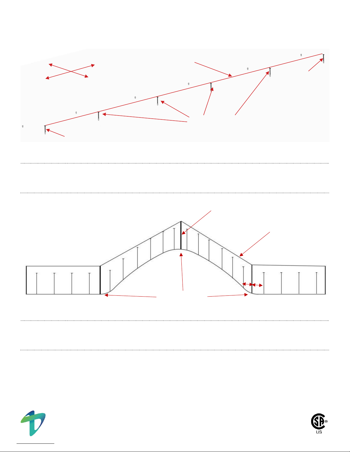
NOTICE
Array Row Installation Consideration: The heights of the posts are infinitely variable within the
tolerances given in the site specific plans, which allows the East-West Array Row to have an
aestheticallty pleasing, smooth, rolling appearance. This is achieved by setting the heights of the
posts with consideration of adjacent racks and slopes. One method is to set the post heights at the
ends of the array row and string line between them as shown in Figure 3.3.4. In long array rows,
intermediate posts may need to be used to prevent a visible sag. At sloping sites, intermediate stakes
may be required at inflection points where the slope changes as shown in Figure 3.3.5. In all instances
a story board should be used.
SET BOLT
NORTH POST ASSEMBLY
GROUND SCREW
SLOTTED TOP OF POST
VERTICAL ADJUSTMENT
GROUND
ANGLE = ± 3 degrees
Figure 3.3.3 - Use Set Bolt to Clamp South Post
ACCEPTABLE
BOLT
CONNECTION
IF DAMAGE TO
THE SET BOLTS
OCCURS
DURING LEG
INSTALLATION
This system conforms to UL Standard 2703 Edition One.
© Copyright 2022, Terrasmart, Inc. All rights reserved. | TerraGlide Portrait Installation Manual | Page 18 of 52
Proprietary and confidential. The information contained in this document is the sole property of Terrasmart.
Any reproduction in part or as a whole without written permission of Terrasmart is prohibited
www.terrasmart.com
271167
Figure 3.3.4 - String Line South Post Assemblies
NOTICE
String Line Technique Consideration: To avoid visible sag in alignment due to gravity on string line, it
is recommended that no more than 4 racks are stringlined at a time.
Figure 3.3.5 - String Lining Between Inflection Points
NOTICE
String Line Technique Consideration: When string lining on undulating surfaces additional feathering
will need to be done at the inflection points. Legs should be moved to that beam ends line up while
leg tolerances are still met.
N
W
E
S
SET HEIGHT
SET HEIGHT
RAISE TO MEET STRING LINE
STRING LINE
INFLECTION POINTS
STRING LINE
STAKE
X
X

This system conforms to UL Standard 2703 Edition One.
© Copyright 2022, Terrasmart, Inc. All rights reserved. | TerraGlide Portrait Installation Manual | Page 19 of 52
Proprietary and confidential. The information contained in this document is the sole property of Terrasmart.
Any reproduction in part or as a whole without written permission of Terrasmart is prohibited
www.terrasmart.com
271167
STEP 6: Install Rafter
Lift Rafter Assembly onto North and South Posts. Insert 1/2”-13 x 4” bolt through the Rafter and top slot of the North and
South Posts as shown in Figure 3.3.6 and tighten fastener finger-tight. Adjust height of the North Post until tilt angle is
within tolerance as shown in Figure 3.3.7. Tighten Set Bolt to clamp the post at the desired height. The Gripple Seismic tab
is to be installed on the interior side of the rack, with cable loop directly below the bolt.
Figure 3.3.6 - Rafter Fastened to North and South Post Assembly
Figure 3.3.7 - Tilt Adjustment of Rafter
GROUND
LEVEL
TILT ANGLE
RAISE/ LOWER
TO ADJUST
TILT ANGLE
SOUTH POST
1/2”-13 X 4” SERRATED FLANGE HEX BOLT
NOMINAL TORQUE = 64 FT-LBS
TORQUE RANGE = 45 –80 FT-LBS
1/2”-13 SERRATED NUT
RAFTER
NORTH POST
GRIPPLE SEISMIC TAB
WASHER PLATE
1/2”-13 X 4” SERRATED FLANGE HEX BOLT
NOMINAL TORQUE = 64 FT-LBS
TORQUE RANGE = 45 –80 FT-LBS
WASHER PLATE
WASHER PLATE
This system conforms to UL Standard 2703 Edition One.
© Copyright 2022, Terrasmart, Inc. All rights reserved. | TerraGlide Portrait Installation Manual | Page 20 of 52
Proprietary and confidential. The information contained in this document is the sole property of Terrasmart.
Any reproduction in part or as a whole without written permission of Terrasmart is prohibited
www.terrasmart.com
271167
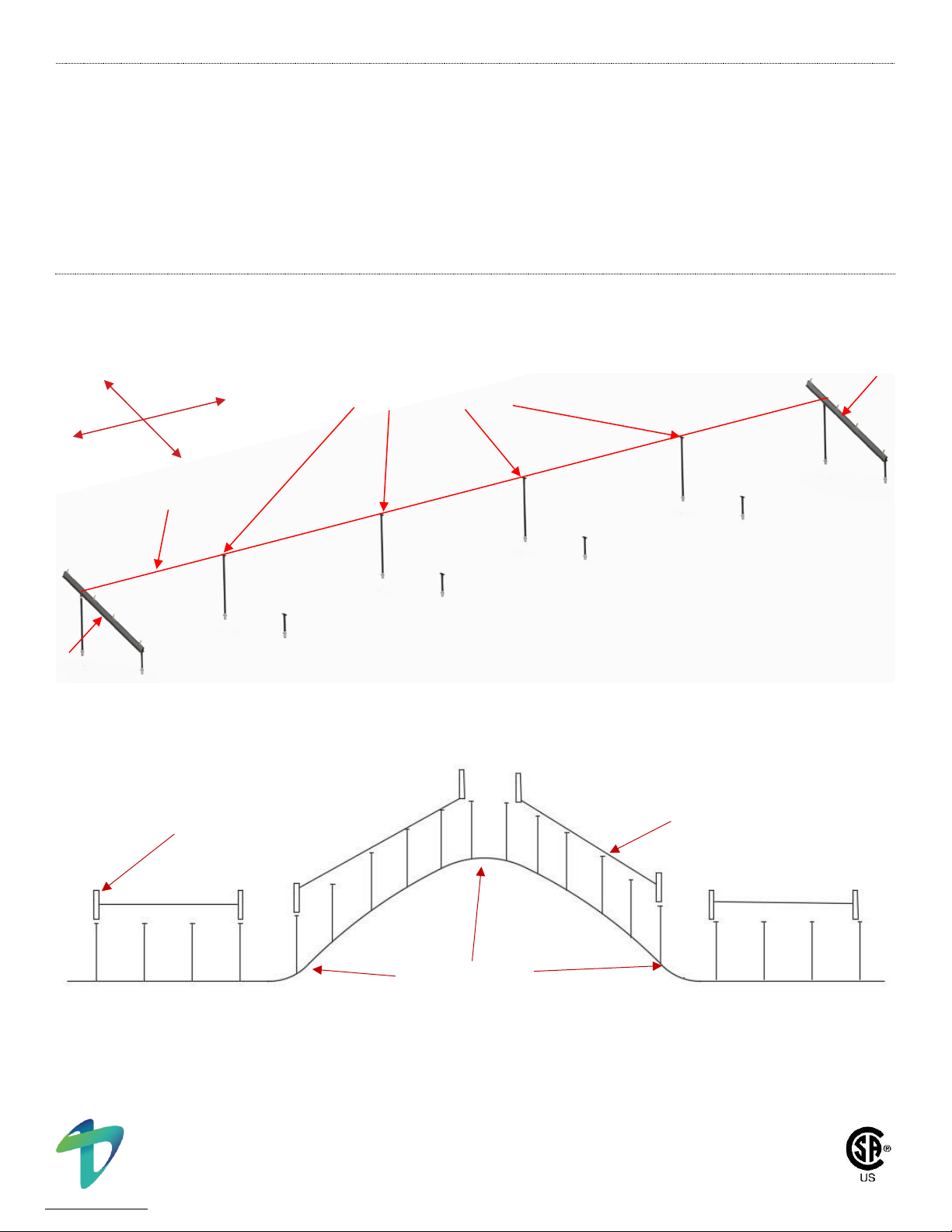
NOTICE
Array Row Installation Consideration: The heights of the posts are infinitely variable within the
tolerances given in the site specific plans, which allows the East-West Array Row to have an
aestheticallty pleasing, smooth, rolling appearance. This is achieved by setting the heights of the
posts with consideration of adjacent racks and slopes. In order to achieve this, feathering of the posts
will be needed. One method is to set the post heights at the ends of the array row and string line
between them as shown in Figure 3.3.8. In long array rows, intermediate posts may need to be used
to prevent a visible sag. At sloping sites, set Rafters and North Posts to the required tilt angle on each
side of the inflection points and stringline between them as shown in Figure 3.3.9. In all instances a
story board should be used.
Figure 3.3.8 - String Line North Post Assemblies
Figure 3.3.9 - Rafters Set at Inflection Points
N
W
S
E
RAFTER
RAFTER
STRING LINE
RAISE TO MEET STRING LINE
INFLECTION POINTS
STRING LINE
RAFTERS
Table of contents
Other Terrasmart Inverter manuals
Popular Inverter manuals by other brands


Mitsubishi Electric
Mitsubishi Electric FR-A8AY E KIT instruction manual

Generac Power Systems
Generac Power Systems 20 kW Synergy owner's manual

INVT
INVT iMars BG10KTR Operation manual

Toshiba
Toshiba VLP Technology Q9 Plus Installation & operation manual

RND power
RND power 320-00133 user manual

IOTA
IOTA IIS3P Series user manual