TURNTABLES OR
AUTOMATIC CHANGERS
The 730 has provision for connecting
two
re
co
rd playing unit
s.
All record
playing units pro
vi
de two or
th
ree cables
(aside from the power cord) for connec-
tion to
th
e
730.
These are t
he
left and right
channel signal cables and the ground
connection. (Some turntables combine
t
he
ground connection
wi
th
one of the
signal
ca
bles.)
The
two signal cables are
usually identified as "left channel" and
"rig
ht
channel" by a color code or tabs, or
the channel identifications are molded into
the
insulators around the pin-type RCA
connectors. Determine which of the
cables
is
left and which rig
ht
and insert
them into
th
e two corresponding
receptacles on
th
e rear panel of
th
e
73
0
marked PHONO 1. Press them in
as
fa
r
as
they wi
ll
go so they a
re
seated snug
ly
.
If
a separate ground wire
1s
pro
v·
de
d,
connect its
lu
g
or
s
tr
ipped end under the
knurled
nu
tmarked GND on the rear panel
of the 730. The phonograph sign
al
connec
ti
ons are now
co
mp
lete.
If
a second
re
cord
pl
aying u
ni
t
1s
lo be
u
se
d connect
it
to
th
e PHONO 2 inputs
in
the
sa
me man
ne
r as
th
e
fi
rs
t
un
it
was
connected
to
PHONO 1.
Note: The 730 is designed
to
operate
with a
hrgh
quality Magnetic car rid
ge.
If
yo
u purchased our 730 and t
rn
b
ie
separately,be sure the turn able is
equipped ith cartri
dge
of this typ
e.
lnser t e AC power cord of your
urntab
le
into the AC rec
ep
tac
le
marked
UNSWITCHED on the rear of
t~
1e
730.Th
is
re
ceptac
le
is "
Ii
e" so long as the 730
itself
is
connected to a live
AC
outl
et
,
regardlessofwhether the 730
is
itself
o erating.
Yo
ur turntab
le
or au
tomaf
c
changers
o
ul
d
be
co
nnec ed to his
receptacle.
FM ANTENNA CONNECTIONS
A "T"-shaped, folded
dip
ole antenna
is
provided with the 730 for
FM
reception.
However,
FM
performance of the 730 will
be
greatly enhanced
if it
is connected
to
an
outdoor antenna system. Many
apartment buildings
in
urban areas
provide a mas
ter
antenna system for
television reception which c
an
often be
used for
FM
purposes.
In
some suburban
and rural areas,
cab
le television systems
exist that
ca
n also beused for FM
reception.
In
fa
c
t,
television antennas on
private houses are often good for
FM
reception.
Two types ofwire, 300 ohm and 75
ohm, are used
as
lead-
in
for
outdoor
an
tenna systems.
Eith
er
type can be
co
nn
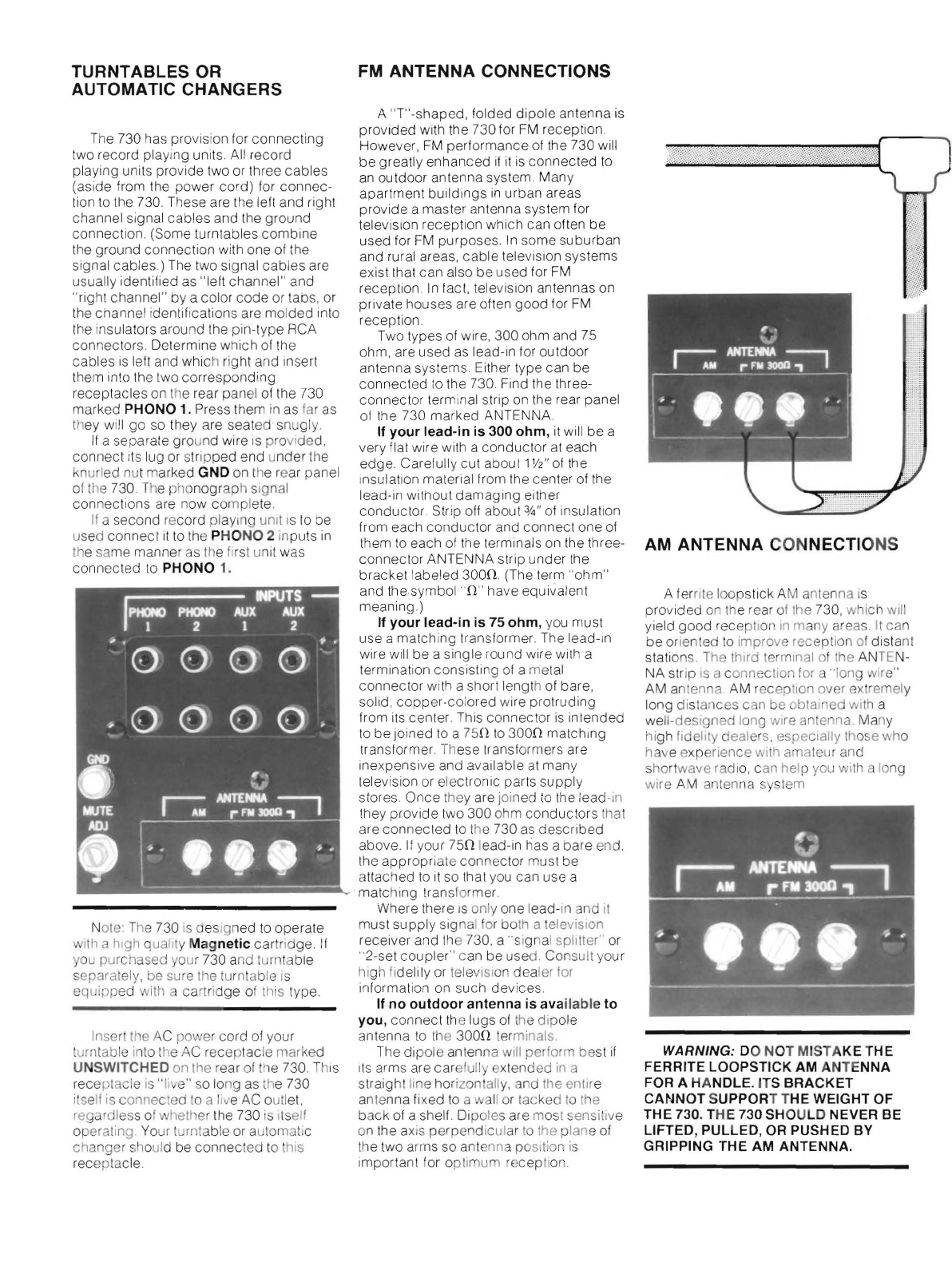
ected to the 730.Find the three-
connector terminal strip
on
the rear panel
of the 730 marked ANTENNA
If your lead-in is 300 ohm,
it
wi
ll
be a
very flat wire with a conductor
at
each
ed
ge
. Carefully cut about 1
½"
of
the
insulation material from the
ce
nter of the
lead-
in
without damaging either
conductor.Strip o
ff
about ¾"
of
insulation
from each
co
nductor
an
d
co
nnectone
of
them
to
each
of
th
e terminalson the three-
connector ANTENNA strip under the
bracket labeled 30
0!1
.(The term "ohm"
and the symbol •
ff
'
ha
ve equivalent
meaning
.)
If your lead-in is 75 ohm, you must
use a matching transformer.
The
lead-in
wire will be a single round wire with a
termination consisting
of
a me
tal
connector with a short length of bare,
solid,copper-colored w
ir
e protruding
from
it
s center. This co
nn
ector
is
inlended
to
be joined to a 75
!1
to
300
!1
matching
transformer These
tr
ansformers are
inexpensi
ve
and available at many
le
levision or electronic parts s
upp
ly
stores Once they are j
oi
ned
lo
the lead-in
they provide two 300 ohm conductors hat
are connected
to
the 730
as
described
above. If your
75
!1 lead-in has a bare
en
d,
the appropriate connec
tor
must be
attached
to
it
so that
you
can use a
·matchi
ng
trans
fo
rmer.
Where there is only one lead-
in
nd it
must supply sig
na
l or bo
th
a television
re
ceiver
an
d
th
e 730, a signal splitter"'
or
··
2-set coupler" c
an
be use
d.
Consult your
high fi
de
l
it
y
or
tel
e
vi
si
on
dealer for
in
fo
rmati
on
on such devices
If no outdoor antenna is available to
you, connect
th
e lugs of the dipole
antenna
to
the 300
!1
t
er
minals
Th
e dipole antenna
wr
ll perform best
if
its
ar
ms are car fully x
ten
ded in a
straight l
rne
horizon
all
y,
and the en
ti
re
an
te
nna
fi
xed
to
aw
II
or
ta
cked to the
ba
ck
of a shell.
Di
poles are most sensitive
on the
ax
is
perpendic
ul
ar
to
the pl
an
e of
th
e two arms so
an
te
nn
a position
is
importa
nt
for optimum r cep
t1
o
n.
AM
ANTENNA CONNECTIONS
A ferrite loops
ti
ck AM antenna
is
provided
on
th
e rear of the 730, which
writ
yield good reception
in
many areas. It
ca
n
be orien ed
to
improve reception of dista
nt
stations. The third
te
rminal of the
AN
TE
N-
NA s
tr
ip
is
connection for
··i
on
ir
e"
AM
anten
na
.
AM
reception over
ex
remely
long distances can be obtai ed with a
well-designed long wire ante, na.
Ma
ny
hi
gh fideli
ty
dealers, especially those
wh
o
have experience with amateur and
sho
rt
wave radi
o,
c
an
help you wi
th
long
wire
AM
antenna sy
st
em
WARNING:
DO NOT MISTAKE THE
FERRITE LOOPSTICK AM ANTENNA
FOR A HANDLE.
IT
S BRACKET
CANNOT SUPPORT THE WEIGHT OF
THE 730. THE 730 SHOULD NEVER
BE
LIFTED, PULLED, OR PUSHED
BY
GRIPPING THE
AM
ANTENNA.