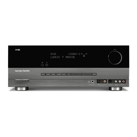
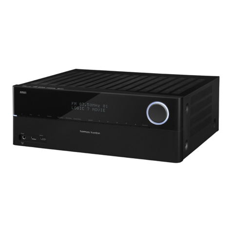
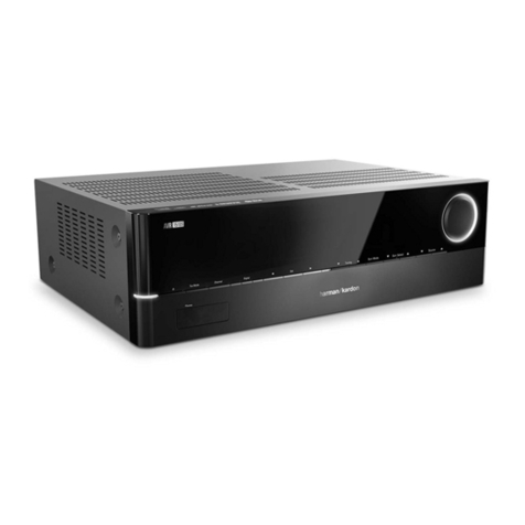
Harman Harman/kardon AVR 161 User manual

Harman Kardon Service Manual
AVR 161/230
5.1 CHANNEL 85 Watt per channel A/V RECEIVER
Released EU2013 Harman Consumer Group, Inc. Rev 1.1,03/2016
8500 Balboa Boulevard
Northridge, California 91329
CONTENTS
EXPLODED VIEW AND PARTS 14
BIAS ADJUSTMENT 15
PARTS LIST 16
SEMICONDUCTOR PINOUTS 50
PCB DRAWINGS 156
BLOCK DIAGRAMS 165
WIRING DIAGRAM 166
SCHEMATIC DIAGRAMS 167
FRONT PANEL CONTROLS 3
REAR PANEL CONNECTORS 5
REMOTE CONTROL FUNCTIONS 7
PROCESSOR RESET 9
TROUBLESHOOTING 10
SPECIFICATIONS 11
PACKAGE DRAWING 12
DISASSEMBLY 13

®
Audio/video receiver
AVR 1710,AVR 171,AVR 171/230C
AVR 1610,AVR 161,AVR 161/230C
Owner’s Manual
Harman Kardon
AVR 161 Service Manual
Page 2 of 178

AVR Front-Panel Controls
Front-Panel Controls
Power
Indicator
Front-Panel
Display
Volume
Knob
Set
Button
IR
Sensor
Power
Button
Left/Right
Buttons
Headphone Jack/
EzSet/EQ
Mic Input
Audio Input
Button
Surround Modes
Select Buttons
Surround Mode
Category Button
Up/Down Buttons/
Tuning Buttons
USB
Port
Tuning Mode Button (AVR
1710/AVR 1610)/
RDS Button (AVR 171/
AVR 161)
Channel Volume
Adjust Button
Source Select
Buttons
4
Harman Kardon
AVR 161 Service Manual
Page 3 of 178

English
AVR Front-Panel Controls
Front-Panel Controls, continued
Power indicator/Power button: The AVR has three different power modes:
Off (Power indicator glows solid amber):The Off mode minimizes energy consumption•
when you’re not using the AVR. When the AVR is off, it will not automatically turn on
or play audio in response to an AirPlay stream from a networked device (AVR 1710/
AVR 171 only). When the AVR is off, pressing the Power button turns it on. To turn
the AVR off when it is on, press the Power button for more than three seconds. The
Front-Panel Display will indicate “Your device is switched off” for two seconds, then
will switch off.
NOTE: You can use the System Setup menu to set the AVR to automatically enter
the off mode after it has been in the Sleep mode for a certain period of time. See
System Settings, on page 34.
Sleep• (Power indicator glows solid amber and front-panel display indicates “Device
sleep”): The Sleep mode powers-down some of the AVR’s circuitry, but allows the
AVR to automatically turn on and play audio in response to an AirPlay or DLNA
DMR stream from a networked device (AVR 1710/AVR 171 only). When the AVR is
in Sleep, pressing the Power button turns it on. To put the AVR into Sleep when it is
on, press the Power button for less than three seconds. The front-panel display will
indicate “Device sleep” while the AVR is in the Sleep mode.
NOTE: The AVR will automatically enter the Sleep mode after 30 minutes of no audio
signal or user control input , unless USB, iPod, Home Network, vTuner, AirPlay, or
DLNA DMR is active. In these cases, the AVR will automatically enter the Sleep mode
after the number of hours set in the Auto Power Off system setting. See System
Settings, on page 34.
On• (Power indicator glows solid white): When the AVR is on it is fully operational.
Headphone jack/EzSet/EQ Mic input: Connect a 1/4” stereo headphone plug to this
jack for private listening. This jack is also used to connect the supplied microphone for
the EzSet/EQ setup procedure described in Configure the AVR For Your Speakers, on
page 22.
Tuning Mode button (AVR 1710/AVR 1610 only): Press this button to toggle the radio
between the manual (one frequency step at a time) and automatic (seeks frequencies
with acceptable signal strength) FM tuning mode. The button also toggles the radio
between stereo and mono modes when an FM station is tuned in.
RDS button (AVR 171/AVR 161 only): When listening to an FM radio station that
broadcasts RDS information, this button activates the various RDS functions.
USB port: The USB port can be used to play audio files from an Apple iOS®device
connected to the port, and can also be used to play MP3 and WMA audio files from a USB
device inserted into the port. Insert the connector or device into the USB port oriented so
it fits all the way into the port. You may insert or remove the connector or device at any
time – there is no installation or ejection procedure.
You can also use the USB port to perform firmware upgrades. If an upgrade for the AVR’s
operating system is released in the future, you will be able to download it to the AVR
using this port. Complete instructions will be provided at that time.
IMPORTANT: Do not connect a PC or other USB host/controller to this port, or you
may damage both the AVR and the other device.
Channel Volume Adjust button: Press this button to activate the individual channel
level adjustment. After pressing this button, use the Up/Down buttons/Tuning buttons to
select the channel for adjustment and use theLeft/Right buttons to adjust the channel’s
level.
Audio Input button: Press this button to change the audio input connection for the current
source. Use the Left/Right buttons to cycle through the available input connections, and
press the Set button to assign the currently-displayed connection to the source.
IR sensor: This sensor receives infrared (IR) commands from the remote control. Make
sure that the sensor is not blocked.
Set button: Press this button to select the currently highlighted menu item.
Left/Right buttons: Use these buttons to navigate the AVR’s menus.
Front-panel display: Various messages appear on this two-line display in response to
commands and changes in the incoming signal. In normal operation, the current source
name appears on the upper line, while the active surround mode is displayed on the
lower line. When the on-screen display menu system (OSD) is in use, the current menu
settings appear.
Up/Down buttons/Tuning buttons: Use these buttons to navigate the AVR’s menus.
When the radio is the active source, use these buttons to tune stations according to the
setting of the Tuning Mode button (see above).
Surround Mode Category button: Press this button to select a surround-sound
category. Each press changes the surround-mode category: Auto Select, Virtual, Stereo,
HARMAN NSP, Movie, Music and Video Game. To change the specific surround-sound
mode within the category, use the Surround Mode Select buttons. See Audio Processing
and Surround Sound, on page 29, for more information about surround modes.
Surround Mode Select buttons: After you have selected the desired surround-mode
category, press these buttons to select a specific mode within the category, such as to
change from Dolby®Pro Logic®II Movie mode to DTS®NEO:6 Cinema mode. Surround
mode availability depends on the nature of the source input signal, i.e., digital versus
analog, and the number of channels encoded within the signal.
Source Select buttons: Press these buttons to select the active source.
Volume knob: Turn this knob to raise or lower the volume.
5
Harman Kardon
AVR 161 Service Manual
Page 4 of 178

AVR Rear-Panel Connectors
6
Rear-Panel Connectors
HDMI/MHL Input
Connector
HDMI Input
Connectors
Power Cord
(AVR 1710)
HDMI Output
Connectors
Analog Video
Connectors
AVR 1710/AVR 171
Subwoofer
Pre-Out
Connectors
Radio Antenna
Connectors
Digital Audio
Connectors Fan Vents
Speaker
Connectors
Network
Connector
AC Input
Connector (AVR 171)
IR and Trigger
Connectors
Analog Audio
Connectors
HDMI/MHL Input
Connector
HDMI Input
Connectors
Power Cord
(AVR 1610)
HDMI Output
Connector
Analog Video
Connectors
AVR 1610/AVR 161
Subwoofer
Pre-Out
Connector
Radio Antenna
Connectors
Digital Audio
Connectors
Speaker
Connectors
Network
Connector
AC Input
Connector
(AVR 161)
IR and Trigger
Connectors
Analog Audio
Connectors
Harman Kardon
AVR 161 Service Manual
Page 5 of 178

English
AVR Rear-Panel Connectors
7
Rear-Panel Connectors, continued
Digital Audio connectors: If your non-HDMI source devices have digital outputs,
connect them to the AVR’s digital audio connectors. NOTE: Make only one type of digital
connection (HDMI, optical or coaxial) from each device. See Connect Your Audio and Video
Source Devices, on page 16, for more information.
Radio Antenna connectors: Connect the supplied AM and FM antennas to their
respective terminals for radio reception.
Analog Audio connectors: The following analog audio connectors are provided:
Analog Audio Input connectors:• Use the AVR’s Analog Audio Input connectors for
source devices that don’t have HDMI or digital audio connectors. See Connect Your
Audio and Video Source Devices, on page 16, for more information.
Zone 2 Out connectors (AVR 1710/AVR 171 only):• Connect these jacks to an
external amplifier to power the speakers in the remote zone of a multizone system.
Network connector: If your home network is wired, use a Cat. 5 or Cat. 5E Ethernet
cable (not supplied) to connect the AVR’s Network connector to your home network to
enjoy Internet radio and content from DLNA-compatible devices that are connected to the
network. See Connect to Your Home Network, on page 18, for more information.
Subwoofer Pre-Out connector: Connect this jack to a powered subwoofer with a line-
level input. See Connect Your Subwoofer, on page 15, for more information. NOTE: The
AVR 1710 and AVR 171 have two subwoofer connectors.
HDMI Output connectors: If your TV has an HDMI connector and you are connecting
HDMI source devices to the AVR, use an HDMI cable (not included) to connect it to
the AVR’s HDMI Out connector. NOTE: The AVR 1710 and AVR 171 have two HDMI Out
connectors.
Notes on using the HDMI Output connector:
When connecting a DVI-equipped display to the HDMI Out connector, use an•
HDMI-to-DVI adapter and make a separate audio connection.
Make sure the HDMI-equipped display is HDCP (High-bandwidth Digital Content•
Protection)-compliant. If it isn’t, do not connect it via an HDMI connection; use an
analog video connection instead and make a separate audio connection.
AVR 1710/AVR 171 only: If you have connected a 3D-capable TV to HDMI Out 1•
and a 2D-capable TV to HDMI Out 2, the AVR will not allow 3D playback when
both TVs are powered on. To watch 3D content, turn off the AVR and both TVs,
then first turn on the 3D TV, then turn on the AVR, and finally turn on the 3D
source device. Do NOT turn the 2D TV back on.
HDMI/MHL Input connector: If you have a Roku Streaming Stick or other MHL-capable
device, connect it only to this HDMI/MHL In connector. If you do not have an MHL device
you can use this connector for an HDMI-capable device.
Speaker connectors: Use two-conductor speaker wire to connect each set of terminals
to the correct speaker. See Connect Your Speakers, on page 14, for more information.
NOTE: The Assigned Amp speaker connectors (AVR 1710/AVR 171 only) are used
for the surround back or Front Height channels in a 7.1- channel home theater, or
you can reassign them to a remote room for multizone operation or to front height
channels for Dolby®Pro Logic IIz operation. See Place Your Speakers, on page 11,
for more information.
Analog Video connectors: The following Analog Video connectors are provided:
Composite Video Input connectors:• Use composite video connectors for video
source devices that don’t have HDMI connectors. You will also need to make an
audio connection from the source device to the AVR. See Connect Your Audio and
Video Source Devices, on page 16, for more information.
Composite Video Monitor Out connector:• If your TV or video display does not
have an HDMI connector, or if your TV does have an HDMI connector but you are
connecting some source devices with only composite video connectors, use a
composite video cable (not included) to connect the AVR’s Composite Video Monitor
Out connector to your TV ’s composite video input.
HDMI®Input connectors: An HDMI connection transmits digital audio and video signals
between devices. If your source devices have HDMI connectors, using them will provide
the best possible video and audio performance quality. Since the HDMI cable carries
both digital video and digital audio signals, you do not have to make any additional audio
connections for devices you connect via the HDMI connection. See Connect Your Audio
and Video Source Devices, on page 16, for more information.
IR and Trigger connector: The following IR and trigger connectors are provided:
IR In connectors:• When the IR sensor on the front panel is blocked (such as when
the AVR is installed inside a cabinet), connect an optional IR receiver to the IR In
jack.
12V Trigger connector:• This connector provides 12V DC whenever the AVR is on. It
can be used to turn on and off other devices such as a powered subwoofer.
Zone 2 IR Input connector (AVR 1710/AVR 171 only):• Connect a remote IR
receiver located in Zone 2 of a multizone system to this jack to control the AVR from
the remote zone.
Fan Vents (AVR 1710/AVR 171 only): These vents are used by the AVR’s fan to cool the
system. Maintain a clearance of at least three inches (75mm) from the nearest surface to
avoid overheating the unit. It is normal for the fan to remain off at most normal volume
levels. An automatic temperature sensor turns the fan on only when it is needed.
IMPORTANT NOTE: Never block the fan vents. Doing so could allow the AVR to
overheat to dangerous levels.
AC Input connector (AVR 171/AVR 161 only): After you have made and verified all
other connections, plug the supplied AC power cord into this receptacle and into an
unswitched wall outlet.
Power cord (AVR 1710/AVR 1610 only): After you have made and verified all other
connections, plug the power cord into an unswitched wall outlet.
Harman Kardon
AVR 161 Service Manual
Page 6 of 178

AVR System Remote Control Functions
8
System Remote Control Functions
Source Selector Buttons
Power Off Button
Power On Button
Back/Exit Button
Volume Up/Down Buttons
Mute Button
Zone 2 Button
(AVR 1710/AVR 171 only)
Home Button
AVR Button
OK Button
Clear Button
Delay Button
IR Transmitter
Surround Modes Button
Number Buttons
Test Tone Button
OSD/Menu Button
Sleep Button
Display Dimmer Button
Memory Button
RDS Button
Previous Channel Button
Transport Control Buttons
Info/Option Button
Direct Button
Preset Scan Button
Channel/Tuner Buttons
Up/Down/Left/Right
Buttons
Harman Kardon
AVR 161 Service Manual
Page 7 of 178

9
English
AVR System Remote Control Functions
9
System Remote Control Functions, continued
In addition to controlling the AVR, the AVR remote is capable of controlling eight other
devices, including an iPod/iPhone device connected to the AVR’s front-panel USB port.
During the installation process, you may program the codes for each of your source
components into the remote. (See Program the Remote to Control Your Source Devices
and TV, on page 21, for programming information.) To operate a component, press its
Source Selector button to change the remote’s control mode.
A button’s function depends on which component is being controlled. See Table A13 in
the Appendix for listings of the functions for each type of component. Most of the buttons
on the remote have dedicated functions, although the precise codes transmitted vary
depending on the specific device being controlled. Due to the wide variety of functions for
various source devices, we have included only a few of the most-often used functions on
the remote: number buttons, transport controls, television-channel control, menu access
and power on and off. Buttons dedicated to the AVR – AVR Power On/Off, Surround
Modes, Volume, Mute, Delay and Sleep Settings – are available at any time, even when
the remote is controlling another device.
Power On/Power Off buttons: Press these buttons to turn the AVR on and put it into
Sleep or turn it off. See Power Indicator/Power Button, on page 4, for more information.
IR Transmitter: As buttons are pressed on the remote, infrared codes are emitted
through this lens.
Zone 2 button (AVR 1710/AVR 171 only): Use this button to select whether the AVR
commands will affect the main listening area (Zone 1) or the remote zone of a multizone
system (Zone 2). When the remote is in the Zone 2 control mode, the Zone 2 button will
illuminate whenever you press a button.
Mute button: Press this button to mute the AVR’s speaker-output connectors and
headphone jack. To restore the sound, press this button or adjust the volume.
Source Selector buttons: Press one of these buttons to select a source device, e.g.,
Disc, Cable/Sat, Radio, etc. This action will also turn on the AVR and switch the remote’s
control mode to operate the selected source device.
The first press of the Radio button switches the AVR to the last-used tuner band (AM•
or FM). Each successive press changes the band.
The first press of the USB button switches the AVR to the last-used source (USB or•
iPod). Each successive press cycles between the two sources.
The first press of the Network button switches the AVR to the last-used source•
(Network or vTuner). Each successive press cycles between the two sources.
AVR button: Press to put the remote into the AVR control mode.
Surround Modes button: Press this button to access the Surround Modes submenu.
Select a surround-mode category: Auto Select, Virtual Surround, Stereo, HARMAN NSP,
Movie, Music or Game. When you select the category, it is highlighted and the surround
mode changes.
To change the surround mode for the selected category navigate to the Surround Mode
menu in the AVR’s on-screen display menu, select the desired category, and use the Left/
Right buttons to select one of the available surround modes. See the Advanced Functions
section, on page 29, for more information.
OSD/Menu button: When the remote is controlling the AVR, press this button to display
the AVR’s on-screen display (OSD) menu. This button is also used within the tuner menus
and an iPod connected to the AVR’s front-panel USB port, and is also used to display the
main menu on some source devices.
Up/Down/Left/Right buttons: These buttons are used to navigate the menu system and
to operate the tuner.
OK button: This button is used to select items from the menu system.
Back/Exit button: Press this button to return to the previous menu or to exit the menu
system.
Home button: Press this button to display the Home menu for a Roku Streaming Stick™
that is connected to the AVR’s MHL/HDMI connector.
Number buttons: Use these buttons to enter numbers for radio-station frequencies or
to select station presets.
Clear button: Press this button to clear a radio station frequency you have started to
enter.
Test Tone button: Press this button to activate test noise that will circulate through each
speaker, allowing you to adjust the individual speaker levels. Use the Up/Down buttons
to switch the noise to a different speaker and use the Left/Right buttons to change the
volume of the speaker the noise is playing through.
Delay Adjust button: Pressing this button lets you adjust two different types of delay
settings (use the Up/Down buttons to cycle through the settings):
Lip Sync: This setting lets you resynchronize the audio and video signals from a•
source to eliminate a “lip sync” problem. Lip-sync issues can occur when the video
portion of a signal undergoes additional processing in either the source device or the
video display. Use the Left/Right buttons to delay the audio by up to 180ms.
Distance: These settings let you set the delay for each speaker to compensate for the•
different distances they may be from the listening position. Use the Up/Down buttons
to cycle through each of the system’s speakers, and use the Left/Right buttons to set
the distance each speaker is from the listening position. See Manual Speaker Setup,
on page 30, for more information.
Sleep button: Press this button to activate the sleep timer, which turns off the receiver
after a programmed period of time. Each press increases the time by 10 minutes, up to
90 minutes – ending with the “Sleep Off” message.
Volume Up/Down buttons: Press these buttons to raise or lower the volume.
Channel/Tuner buttons: When radio has been selected, press these buttons to select a
preset radio station. While operating a cable, satellite or HDTV set-top box or a television,
press these buttons to change channels.
Info/Option button: Press to display the available option settings for the current
source.
Display Dimmer button: Press this button to dim the AVR’s front-panel Message Display
partially or fully.
Preset Scan button: When Radio is the selected source, press this button to play each of
your preset radio stations in order for five seconds. Pressing the button again to remain
tuned to the current station.
RDS button (AVR 171/AVR 161 only): When listening to an FM radio station that
broadcasts RDS information, this button activates the various RDS functions.
Direct button: Press this button to directly tune to a radio station by using the Number
buttons to enter its frequency.
Memory button: Press this button to save the current radio or vTuner station as a
preset.
Transport Control buttons: These buttons are used to control source devices.
Previous Channel button: When TV is the selected source, press this button to switch
to the previously-tuned channel.
Harman Kardon
AVR 161 Service Manual
Page 8 of 178

34
AVR System Settings
System Settings
The AVR’s System Settings menu lets you customize in what way many of the AVR’s
features operate. Press the OSD/Menu button and navigate to the System line. Press the
OK button to display the System Settings menu.
Panel Timeout: This setting allows you to set theAVR’s front-panel display to automatically
turn off after remaining on for a predetermined time (3 – 10 seconds) each time you use
a control. Set this to “Off” to have the display remain on continually.
Auto Power Off: This setting allows you to set the AVR to automatically switch to the
Off mode after being in the Sleep mode for a predetermined time (1 – 8 hours). See
Power Indicator/Power Button, on page 4, for more information. It also allows the AVR to
automatically switch to the Sleep mode after being on for the predetermined amount of
time. Note that it will not transition to Sleep mode this way if the active source has one
of the Digital Audio Connectors selected as the Audio Input. See Source Setup, on page
23, for more information.
Menu Timeout: This setting allows you to set the amount of time (20 – 50 seconds) a
menu screen will remain on after the last adjustment. Set this to “Off” to have the menus
remain on continually until you press the OSD/Menu button.
Status Message: When the AVR is turned on, the volume is adjusted, the source is
changed or a change in the input signal is detected, a status message will be displayed
on the TV screen. Select how long the message remains visible, from 2 to 10 seconds,
with a default of 3 seconds. Select “Off” if you do not wish to see the status messages on
the TV screen (they will still appear on the AVR’s front-panel display).
Volume Default and Default Volume Setting: These two settings are used together to
program the volume level when you turn on the AVR. Set Volume Default to On, and then
set the Default Volume Setting to the desired turn-on volume. When Volume Default is
set to Off, the AVR will turn on at the last-used volume setting from the previous listening
session.
HDMI Audio to TV: This setting determines whether HDMI audio signals are passed
through the HDMI Monitor Out connector to the video display. In normal operation, leave
this setting at Off, as audio will be played through the AVR. To use the TV by itself, without
the home theater system, turn this setting to On.
HDMI Link: This setting allows the communication of control information among the
HDMI devices in your system. Turn this setting to On to allow control communication
between the HDMI devices; turn the setting to Off to forbid control communication.
Software Update: If a software upgrade is released for your AVR, installation instructions
will be available in the Product Support section of the Web site or from Harman Kardon
customer service. At that time, you may use this submenu to install the upgrade
software.
IMPORTANT: During a software upgrade, do not power off the AVR or use any of its
controls. Doing so could permanently damage the AVR.
Sleep Timer
The sleep timer sets the AVR to play for up to 90 minutes and then turn off
automatically.
Press the Sleep button on the remote, and the time until turn-off will be displayed.
Each additional press of the Sleep button increases the play time by 10 minutes, with a
maximum of 90 minutes. The SLEEP OFF setting disables the sleep timer.
When the sleep timer has been set, the front-panel display will automatically dim to half
brightness.
If you press the Sleep button after the timer has been set, the remaining play time will be
displayed. Press the Sleep button again to change the play time.
The front-panel display will count down during the final 10 seconds before going to Sleep
mode. Pressing any button during this countdown will cancel the process and disable
the Sleep timer.
Processor Reset
If the AVR behaves erratically after a power surge, unplug the AC power cord for at least
3 minutes. Plug the cord back in and turn the AVR on. If this procedure doesn’t help, reset
the AVR’s processor as described below.
NOTE:
A processor reset erases all user configurations, including speaker and level
settings and tuner presets. After a reset, reenter all of these settings from your entries in
the Appendix worksheets.
To reset the AVR’s processor:
1. Press the front-panel Power Button for more than three seconds to turn the AVR off (the
Power Indicator will turn amber).
2. Press and hold the front-panel Surround Mode Category button for at least 5 seconds
until the RESET message appears on the front-panel display.
NOTE:
After performing a processor reset, wait at least 1 minute before pressing any
Source Selector buttons.
If the AVR does not function correctly after a processor reset, contact an authorized
Harman Kardon service center for assistance. Authorized service centers may be located
by visiting our Web site at www.harmankardon.com.
Harman Kardon
AVR 161 Service Manual
Page 9 of 178

35
English
AVR Troubleshooting
Symptom Cause Solution
Unit does not function •NoACpower •EnsurethatthepowercordispluggedintoaliveAC
power outlet
•CheckiftheACoutletisswitch-controlled
Front-panel display lights, but there’s no sound or picture •Intermittentinputconnection
•Muteison
•Volumecontrolisturneddown
•Secureallinputandspeakerconnections
•PressMutebutton
•TurnupVolumecontrol
No sound from any speaker •Amplierisinprotectionmodeduetopossibleshort
circuit
•Amplierisinprotectionmodeduetointernal
problems
•CheckallspeakerwiresatspeakerandAVR
connections for crossed wires
•ContactyourlocalHarmanKardonservicecenter
No sound from center or surround speakers •Incorrectsurroundmode
•Programmaterialismonophonic
•Incorrectspeakerconguration
•Programmaterialisstereo
•Selectasurroundmodeotherthanstereo
•Monoprogramscontainnosurroundinformation
•Checkthespeakercongurationinthesetupmenu
•Thesurrounddecodermaynotcreatecenter-or
surround-channel information from nonencoded
programs
Unit does not respond to remote control commands •Weakbatteriesinremote
•Remotesensorisobscured
•Changebatteriesinremote
•EnsurethattheAVR’sfront-panelremotesensorisin
the line of sight of the remote
Intermittent buzzing in tuner •Localinterference •MovetheAVRorantennaawayfromcomputers,
fluorescent lights, motors or other electrical appliances
(AVR 1710/AVR 171 only): Surround-back speaker
settings cannot be accessed, and the test tone does not
play through the surround back speakers
•Multi-zoneoperationhasbeenselected/AssignedAMP
channels have been assigned to Zone 2
•UsetheSpeakerSetupmenutoreassigntheAssigned
AMP to the surround back left and right channels
Unable to activate remote control Programming mode •SourceSelectorbuttonisnotheldforatleast3
seconds
•BesuretoholdtheSourceSelectorbuttonforatleast
3 seconds
Remote buttons light, but AVR does not respond •RemoteisinZone2mode •PressZone2button(buttonwillnotilluminatewhen
remote is in Zone 1 control mode).
Unable to establish network connection •AVRnetworkprogrammingrequiresrebooting •CycletheAVRintotheOffmode,andthenturniton
again
Additional information on troubleshooting possible problems with your AVR and installation-related issues may be found in the list of “Frequently Asked Questions,” which is located
in the Product Support section of our Web site: www.harmankardon.com
Troubleshooting
Harman Kardon
AVR 161 Service Manual
Page 10 of 178

36
AVR Specifications
Specifications
Audio Section
Stereo power: AVR 1710/AVR 171: 100W per channel,
two channels driven @ 6/8 ohms, 1kHz,
<0.9% THD
AVR 1610/AVR 161: 85W per channel, two
channels driven @ 6/8 ohms, 1kHz, <0.9%
THD
Multichannel power: AVR 1710/AVR 171: 100W per channel,
two channels driven @ 6/8 ohms, 1kHz,
<0.9% THD
AVR 1610/AVR 161: 85W per channel, two
channels driven @ 6/8 ohms, 1kHz, <0.9%
THD
Input sensitivity/impedance: 250mV/27k ohms
Signal-to-noise ratio (IHF-A): 100dB
Surround system adjacent channel
separation:
Dolby Pro Logic/DPLII: 40dB
Dolby Digital: 55dB
DTS: 55dB
Frequency response (@ 1W): 10Hz – 130kHz (+0dB/–3dB)
High instantaneous current
capability (HCC):
±40 amps (AVR 1710/AVR 171);
±29 amps (AVR 1610/AVR 161)
Transient intermodulation
distortion (TIM): Unmeasurable
Slew rate: 40V/sec
FM Tuner Section
Frequency range: 87.5 – 108.0MHz
Usable sensitivity IHF: 1.3µV/13.2dBf
Signal-to-noise ratio (mono/stereo): 70dB/68dB
Distortion (mono/stereo): 0.2%/0.3%
Stereo separation: 40dB @ 1kHz
Selectivity (±400kHz): 70dB
Image rejection: 80dB
IF rejection: 80dB
AM Tuner Section
Frequency range: 520 – 1710kHz (AVR 1710/AVR 1610)
522 – 1620kHz (AVR 170/AVR 160)
Signal-to-noise ratio: 38dB
Usable sensitivity (loop): 500µV
Distortion (1kHz, 50% mod): 1.0%
Selectivity (±10kHz): 30dB
Bluetooth Section
Frequency range: 2402MHz - 2480MHz
Transmitter power: 0-4dBm
Modulation: GFSK, π/4-DQPSK, 8-DPSK
Functions: Streaming audio play, supports Bluetooth
3.0, A2DP v1.2, AVRCP v1.4
Video Section
Television format: NTSC (AVR 1710/AVR 1610);
PAL (AVR 171/AVR 161)
Input level/impedance: 1Vp-p/75 ohms
Output level/impedance: 1Vp-p/75 ohms
Video frequency response (composite
video): 10Hz – 8MHz (–3dB)
HDMI: HDMI 1.4 with 4k x 2k bypass
General Specifications
Power requirement: 120V AC/60Hz (AVR 1710/AVR 1610);
220V – 240V AC/50Hz – 60Hz (AVR 171/
AVR 161)
Power consumption: <0.5W (standby);
510W maximum (AVR 1710/AVR 171);
450W maximum (AVR 1610/AVR 161)
Dimensions (W x H x D): 17-5/16" x 4-3/4" x 11-3/16"
(440mm x 121mm x 300mm)
Weight (AVR 1710/AVR 171): 11 lb (5.1kg)
(AVR 1610/AVR 161): 10 lb (4.6kg)
Depth measurement includes knobs, buttons and terminal connections.
Height measurement includes feet and chassis.
Harman Kardon
AVR 161 Service Manual
Page 11 of 178

2. Package Drawing AVR161/230
MANUAL ASS'Y
BOX,OUT CARTON
3
4
1
DESCRIPTIONNO
CPS1A930
CQXAVR161/230
CPG1A972V
1
1
Q,tyPARTS NO.
CPS1A931PAD,RIGHT
2
1
PAD,LEFT
SET AVR161/230SET
1
5
1
POLY BAG
NO DESCRIPTION PARTS NO. Q,ty
1
2
3
4
5
6
7
1
1
CPB1A190ZPOLY BAG
1. Instruction manual ass'y - Accessories(CQXAVR161/230)
SHEET,QUICK START GUIDE8 CQE1A570Z
1
CABR03PPB
CSA1A039ZANT, AM LOOP(9.5uH/5T)
BATTERY
1
2
FM 1 POL ANT CSA1A018Z 1
2
BATTERY ASS'Y
4
9
3
AM LOOP ANTENNA ASS'Y
6
FM 1 POLE ANT(UL)
78
5
1
9
MICROPHONE ASS'Y
1CJXAVR365MICROMICROPHONE ASS'Y
SNOW PAD (R)
4
BOX ,OUT CARTON
6
SET
5
SNOW PAD (L)
3
MANUAL ASS'Y
1
1
SHEET,SAFETY CQE1A601Z 1
TRANSMITTER ASS'Y
REMOCON
REMOCON ASS'Y CARTAVR161-HK 1
SHEET,QUICK START GUIDE
10 STAPLE CPL0905 3
10
STAPLE
SHEET,SAFETY
CJA2B120Z
CORD,POWER(PLUG+SOCKET)
CORD , POWER(EUR)
Harman Kardon
AVR 161 Service Manual
Page 12 of 178

DISASSEMBLY
Remove the Screws
4. Removing the Main PCB
~
1 6
~
1
21
Remove the Screws
3. Removing the Rear Panel
AVR161/230
1
1. Removing the Top Cabinet
Remove the Screws ~
13
Remove the Screws
2. Removing the Front Panel
1 7
~
1
7
5
4
3
6
2
2
1
3
4
6
5
16 17 18 19 20 2115
1345678 29
13
12
11
10
14
3
1
2
13
12
11
10
7
9
8
4
6
5
Harman Kardon
AVR 161 Service Manual
Page 13 of 178

AVR161/230 EXPLODED VIEW
22
21
S1
S6
S1
S9
S7
S12
S5
S4
S3
S2
NO
17
CTB3+8JFZR
SCREW
SCREW
CTB3+6FFZR
CHD1A012R
SCREW
SCREW
SCREW
CTB3+10JR
CTW3+12JR
CTB3+10JFZR
CTWS3+10GR
9
15
2
23
2
9
DESCRIPTIONPARTS NO. Q,ty
25
SCREW
CHD4A012R
S5
S5
40-1
S10 SCREW CTB3+6JR 2
SCREW CTB3+8JR 4
S6
S8 CTS3+8JFZRSCREW 4
S13SCREW 5
SCREW CTB4+6FFZR 4
42-2
S6
S3
S6
25
15
14
20
42-1
42-3
S7
S3
S7
S6
S6
SCREW
16
FRONT PCB ASS'Y
29
36
40
30
31
32
33
35
34
23
24
25
26
28
27
17
18
19
20
22
21
COP12502E
3
10
11
12
13
15
14
7
6
5
4
9
8
PANEL,FRONT
2
1
INDICATOR,VOLUME
CGW1A533RHZB63
CGL1A300
1
1
1
1
1
1
1
1
40-1
40-2
40-3
40-4
FIP & KEY PCB
PHONE PCB
42MAIN PCB ASS'Y COP12506F1
1
1
1
1
1
1
KNOB,VOLUME CBN1A269B651
1
1
1
KNOB,STANDBY CBT2A1064
1
KNOB,BACK CBT2A1065
POWER LED PCB
VOLUME PCB
FOOT A
FOOT B
CHASSIS,BOTTOM
CABINET,TOP
CUA1A343
CKL1A095
CKC1A219B64
CKL1A094
2
2
1
1
CUSHION , FOOT CHG1A3734
BRACKET , PCB CMD1A810 2
SHEET,BLIND CPE1A009
1
1
PANEL,REAR CKF5A463Z1
41DIGITAL PCB ASS'Y COP12504F
42-1
42-2
MAIN PCB
GUIDE PCB(CARD)
431
SMPS PCB ASS'Y
44COP12509F
37
BADGE, HARMAN/KARDON
CGB1A255Z
WINDOW,FIP CGU2A410A25J
BADGE,AVR161CGB1A260Z
JACK,COVER CGR1A555B63
ORNAMENT,RING CGR1A538G5
INDICATOR,POWER CGL1A265Y
1SHEET , VOLUME CGX1A476Z
HOLDER , LED CMH3A215
BRACKET,HDMI CMD1A8092
38
39
1
42-3 GUIDE PCB(CARD)
NO DESCRIPTIONPARTS NO. Q,ty REMARK
32
2
CUSHION , RUBBER CHG1A160Z
S6
S11
S6
19
28
28
FILTER,FIP CMZ1A145
COVER , SCREWCMD1A8151
HEAT SINK CMY1A388
HOLDER , PCB CHE1704
40-2
40-4
40-3
42-4
42-4 SHIELD PCB
40-5 JACK PCB ASS'Y1
40-5
41
S1
S5
S6
S11
SCREW CTW3+8JR 5
S14 SCREW CTB4+10JFZR 2
S11
PLATE , EARTH TOP CMC1A4162
33
S1
31
S6
BRACKET,H/S CMD1A8022
31
S6
S1
30
S3
S14
S3
S11
S6
S6
5
1
6
7
16
18
17
18
18
18
16
11
4
S8
S8
S8
S8
17
10
3
2
12 13
S10
9
8
S9
S2
S13
37
S4
Harman Kardo
n
AVR 161 Service Manua
l
Pa
g
e 14 of 178
44
1
1
1
1
1
1

AMPLIFIER SECTION BIAS ADJUSTMENT
Measurement condition
.No input signal or volume position is minium.
.Do not adjust at FM/AM
Standard value
.Ideal current = 48mA (±7%)
.Ideal DC Voltage = 22.5mA (±7%)
DC VOLTMETER ; Connect to
CN66(SL),CN61(CNT),CN64(SR),CN62(FR),CN63(FL)
No. Channel Adjust for Adjust
1Front Left 22.5mV (±7%) CN63
2Front Right 22.5mV (±7%) CN62
3Center 22.5mV (±7%) CN61
4Surround Left 22.5mV (±7%) CN66
5Surround Right 22.5mV (±7%) CN64
Harman Kardon
AVR 161 Service Manual
Page 15 of 178

AVR 161 PARTS LIST
Level Ref# Component Description Drawing No
..2
CBN1A269B65
KNOB , VOLUME
..2
CGL1A300 INDICATOR , VOLUME
..2
CGR1A555B63
COVER , JACK AVR1510
..2
CGWAVR161/230
FRONT PANEL ASS'Y
...3
CBT2A1064
KNOB , STANDBY
...3
CBT2A1065
KNOB , BACK
...3
CGB1A255Z
BADGE , HARMAN/KARDON
...3
CGB1A260Z
BADGE , AVR161
...3
CGL1A265Y
INDICATOR , POWER AVR155
...3
CGR1A538G5
ORNAMENT , RING
...3
CGU2A410A25J
WINDOW , FIP AVR170/230
...3
CGW1A533RHZB63
PANEL , FRONT AVR1610
...3
CGX1A476Z
SHEET , VOLUME
...3
CMC1A416
PLATE , EARTH TOP
...3
CMH3A215
HOLDER , LED
...3
CMZ1A145
FILTER AVR1510
Level Ref# Component Description Drawing No
...3
COP12502E
AVR1610 FRONT PCB ASS'Y
......6
C109
CCUS1H104KC
CAP, CHIP(1608, 50V/0.1uF)
......6
C121
CCUS1H151JA
CAP, CHIP(1608, 50V/150pF)
......6
C151
CCUS1H104KC
CAP, CHIP(1608, 50V/0.1uF)
......6
C213
CCUS1H223KC
CAP, CHIP(1608, 50V/0.022uF)
......6
C214
CCUS1H223KC
CAP, CHIP(1608, 50V/0.022uF)
......6
C311
CCUS1H102KC
CAP, CHIP(1608, 50V/1000pF)
......6
C322
CCUS1H102KC
CAP, CHIP(1608, 50V/1000pF)
......6
C351
CCUS1H181JA
CAP, CHIP(1608, 50V/180pF) 1608 SIZE
......6
C352
CCUS1H104KC
CAP, CHIP(1608, 50V/0.1uF)
......6
C361
CCUS1H103KC
CAP, CHIP(1608, 50V/0.01uF) 1608 SIZE
......6
C362
CCUS1H103KC
CAP, CHIP(1608, 50V/0.01uF) 1608 SIZE
......6
C363
CCUS1H104KC
CAP, CHIP(1608, 50V/0.1uF)
......6
C364
CCUS1H104KC
CAP, CHIP(1608, 50V/0.1uF)
......6
C365
CCUS1H104KC
CAP, CHIP(1608, 50V/0.1uF)
......6
C366
CCUS1H104KC
CAP, CHIP(1608, 50V/0.1uF)
......6
C421
CCUS1H104KC
CAP, CHIP(1608, 50V/0.1uF)
......6
C422
CCUS1H104KC
CAP, CHIP(1608, 50V/0.1uF)
......6
C423
CCUS1H680JA
CAP, CHIP(1608, 50V/68pF)
......6
C431
CCUS1H104KC
CAP, CHIP(1608, 50V/0.1uF)
......6
C441
CCUS1H223KC
CAP, CHIP(1608, 50V/0.022uF)
......6
C442
CCUS1H223KC
CAP, CHIP(1608, 50V/0.022uF)
......6
C451
CCUS1H104KC
CAP, CHIP(1608, 50V/0.1uF)
......6
C456
CCUS1H104KC
CAP, CHIP(1608, 50V/0.1uF)
......6
C557
CCUS1H104KC
CAP, CHIP(1608, 50V/0.1uF)
......6
C558
CCUS1H104KC
CAP, CHIP(1608, 50V/0.1uF)
......6
C601
CCUS1H104KC
CAP, CHIP(1608, 50V/0.1uF)
......6
C602
CCUS1H104KC
CAP, CHIP(1608, 50V/0.1uF)
......6
C603
CCUS1H104KC
CAP, CHIP(1608, 50V/0.1uF)
......6
C604
CCUS1H104KC
CAP, CHIP(1608, 50V/0.1uF)
......6
C605
CCUS1H104KC
CAP, CHIP(1608, 50V/0.1uF)
......6
C644
CCUS1H104KC
CAP, CHIP(1608, 50V/0.1uF)
......6
C645
CCUS1H471JA
CAP, CHIP(1608, 50V/470pF)
......6
C646
CCUS1H471JA
CAP, CHIP(1608, 50V/470pF)
......6
C647
CCUS1H104KC
CAP, CHIP(1608, 50V/0.1uF)
......6
C714
CCUS1H104KC
CAP, CHIP(1608, 50V/0.1uF)
......6
C715
CCUS0J475KC
CAP, CHIP(1608, 6.3V/4.7uF, MURATA GRM18) GRM188R60J475KE19D
......6
C732
CCUS1H104KC
CAP, CHIP(1608, 50V/0.1uF)
......6
C751
CCUS1H222KC
CAP, CHIP(1608, 50V/2200pF)
......6
C752
CCUS1H102KC
CAP, CHIP(1608, 50V/1000pF)
......6
C753
CCUS1H102KC
CAP, CHIP(1608, 50V/1000pF)
......6
C754
CCUS1H104KC
CAP, CHIP(1608, 50V/0.1uF)
......6
C801
CCUS1H104KC
CAP, CHIP(1608, 50V/0.1uF)
......6
C802
CCUS1H104KC
CAP, CHIP(1608, 50V/0.1uF)
......6
C813
CCUS1H470JA
CAP, CHIP(1608, 50V/47pF)
......6
C821
CCUS1H471JA
CAP, CHIP(1608, 50V/470pF)
......6
C822
CCUS1H151JA
CAP, CHIP(1608, 50V/150pF)
......6
C830
CCUS1H473KC
CAP, CHIP(1608, 50V/0.047uF)
Harman Kardon
AVR 161 Service Manual
Page 16 of 178

Level Ref# Component Description Drawing No
...3
COP12502E
AVR1610 FRONT PCB ASS'Y
......6
C911
CCUS1H104KC
CAP, CHIP(1608, 50V/0.1uF)
......6
C912
CCUS1H104KC
CAP, CHIP(1608, 50V/0.1uF)
......6
C923
CCUS1H681JA
CAP, CHIP(1608, 50V/680pF)
......6
C924
CCUS1H681JA
CAP, CHIP(1608, 50V/680pF)
......6
C951
CCUS1H104KC
CAP, CHIP(1608, 50V/0.1uF)
......6
C952
CCUS1H104KC
CAP, CHIP(1608, 50V/0.1uF)
......6
D1
CVD1SS355T
DIODE , CHIP , SWITCHING 1SS355(T/B)
......6
D2
CVD1SS355T
DIODE , CHIP , SWITCHING 1SS355(T/B)
......6
D361
CVD1SS355T
DIODE , CHIP , SWITCHING 1SS355(T/B)
......6
D362
CVD1SS355T
DIODE , CHIP , SWITCHING 1SS355(T/B)
......6
D363
CVD1SS355T
DIODE , CHIP , SWITCHING 1SS355(T/B)
......6
D643
CVD1SS355T
DIODE , CHIP , SWITCHING 1SS355(T/B)
......6
D644
CVD1SS355T
DIODE , CHIP , SWITCHING 1SS355(T/B)
......6
D955
CVD1SS355T
DIODE , CHIP , SWITCHING 1SS355(T/B)
......6
IC13
CVISN74ACT04DR
I.C , HEX INVERTERS(SOIC/D-14P) SN74ACT04DR
......6
IC14
CVINJM4580CG
I.C , DUAL OPAMP(SOP-8P)
......6
IC421
HVINJM2244MTE1
I.C , VIDEO SWITCH QRW-6500
......6
IC91
HVTKTC812TB
T.R , CHIP(TS6) KTC812T-B-RTK/P
......6
IC92
HVTKTC812TB
T.R , CHIP(TS6) KTC812T-B-RTK/P
......6
L451
HLZ9Z014Z CHIP , BEAD HU-1M4516-600JT
......6
Q111
CVTRT1P144C
T.R,RT1P144C(10K-47K) RT1P144C-T112-1
......6
Q112
CVTRT1N144C
T.R,RT1N144C(10K-47K) RT1N144C
......6
Q113
CVTRT1N144C
T.R,RT1N144C(10K-47K) RT1N144C
......6
Q114
CVTRT1N144C
T.R,RT1N144C(10K-47K) RT1N144C
......6
Q252
CVTRT1N144C
T.R,RT1N144C(10K-47K) RT1N144C
......6
Q362
CVTRT1N141C
T.R,RT1N141C(10K-10K) RT1N141C
......6
Q363
CVTRT1P141C
T.R,RT1P141C(10K-10K) RT1P141C-T112-1
......6
Q373
CVTRT1P144C
T.R,RT1P144C(10K-47K) RT1P144C-T112-1
......6
Q721
CVTRT1N144C
T.R,RT1N144C(10K-47K) RT1N144C
......6
Q906
CVTRT1P144C
T.R,RT1P144C(10K-47K) RT1P144C-T112-1
......6
Q907
CVTRT1P144C
T.R,RT1P144C(10K-47K) RT1P144C-T112-1
......6
Q955
CVTRT1N144C
T.R,RT1N144C(10K-47K) RT1N144C
......6
R101
CRJ10DJ221T
RES, CHIP(1608/5%/220ohm) 00200-0101
......6
R102
CRJ10DJ681T
RES, CHIP(1608/5%/680ohm) 00200-0120
......6
R104
CRJ10DJ103T
RES, CHIP(1608/5%/10Kohm) 00200-0096
......6
R108
CRJ10DJ0R0T
RES, CHIP(1608/5%/0ohm) 00200-0090
......6
R109
CRJ10DJ0R0T
RES, CHIP(1608/5%/0ohm) 00200-0090
......6
R110
CRJ10DJ0R0T
RES, CHIP(1608/5%/0ohm) 00200-0090
......6
R111
CRJ10DJ0R0T
RES, CHIP(1608/5%/0ohm) 00200-0090
......6
R112
CRJ10DJ0R0T
RES, CHIP(1608/5%/0ohm) 00200-0090
......6
R113
CRJ10DJ0R0T
RES, CHIP(1608/5%/0ohm) 00200-0090
......6
R122
CRJ10DJ100T
RES, CHIP(1608/5%/10ohm) 1608 SIZE
......6
R151
CRJ10DJ0R0T
RES, CHIP(1608/5%/0ohm) 00200-0090
......6
R201
CRJ10DJ101T
RES, CHIP(1608/5%/100ohm) 00200-0100
......6
R202
CRJ10DJ101T
RES, CHIP(1608/5%/100ohm) 00200-0100
......6
R203
CRJ10DJ101T
RES, CHIP(1608/5%/100ohm) 00200-0100
......6
R211
CRJ10DJ101T
RES, CHIP(1608/5%/100ohm) 00200-0100
......6
R213
CRJ10DJ272T
RES, CHIP(1608/5%/2.7Kohm)
......6
R214
CRJ10DJ272T
RES, CHIP(1608/5%/2.7Kohm)
......6
R251
CRJ10DJ222T
RES, CHIP(1608/5%/2.2Kohm) 00200-0142
......6
R252
CRJ10DJ393T
RES, CHIP(1608/5%/39Kohm)
......6
R312
CRJ10DF1001T
RES, CHIP(1608/1%/1Kohm) RM06FB1K
......6
R313
CRJ10DF1501T
RES, CHIP(1608/1%/1.5Kohm) 1.5K /1/10W/F
......6
R314
CRJ10DF1801T
RES, CHIP(1608/1%/1.8Kohm) 1.8K /1/10W/F
......6
R315
CRJ10DF2701T
RES, CHIP(1608/1%/2.7Kohm) RM06FB2K7
......6
R316
CRJ10DF3301T
RES, CHIP(1608/1%/3.3Kohm)
......6
R322
CRJ10DF1001T
RES, CHIP(1608/1%/1Kohm) RM06FB1K
......6
R323
CRJ10DF1501T
RES, CHIP(1608/1%/1.5Kohm) 1.5K /1/10W/F
......6
R324
CRJ10DF1801T
RES, CHIP(1608/1%/1.8Kohm) 1.8K /1/10W/F
......6
R325
CRJ10DF2701T
RES, CHIP(1608/1%/2.7Kohm) RM06FB2K7
......6
R326
CRJ10DF3301T
RES, CHIP(1608/1%/3.3Kohm)
......6
R327
CRJ10DF5601T
RES, CHIP(1608/1%/5.6Kohm) 00200-0234
......6
R328
CRJ10DF5601T
RES, CHIP(1608/1%/5.6Kohm) 00200-0234
......6
R351
CRJ10DJ750T
RES, CHIP(1608/5%/75ohm) 1608 SIZE
......6
R352
CRJ10DJ103T
RES, CHIP(1608/5%/10Kohm) 00200-0096
Harman Kardon
AVR 161 Service Manual
Page 17 of 178

Level Ref# Component Description Drawing No
...3
COP12502E
AVR1610 FRONT PCB ASS'Y
......6
R361
CRJ10DJ1R0T
RES, CHIP(1608/5%/1ohm) 1608 SIZE
......6
R362
CRJ10DJ1R0T
RES, CHIP(1608/5%/1ohm) 1608 SIZE
......6
R363
CRJ10DJ103T
RES, CHIP(1608/5%/10Kohm) 00200-0096
......6
R364
CRJ10DJ4R7T
RES, CHIP(1608/5%/4.7ohm) 00200-0099
......6
R365
CRJ10DJ4R7T
RES, CHIP(1608/5%/4.7ohm) 00200-0099
......6
R366
CRJ10DJ103T
RES, CHIP(1608/5%/10Kohm) 00200-0096
......6
R367
CRJ10DJ0R0T
RES, CHIP(1608/5%/0ohm) 00200-0090
......6
R368
CRJ10DJ102T
RES, CHIP(1608/5%/1Kohm) 00200-0094
......6
R375
CRJ10DJ103T
RES, CHIP(1608/5%/10Kohm) 00200-0096
......6
R376
CRJ10DJ221T
RES, CHIP(1608/5%/220ohm) 00200-0101
......6
R377
CRJ10DJ473T
RES, CHIP(1608/5%/47Kohm) 00200-0185
......6
R402
CRJ14CJ4R7T
RES, CHIP(3216/5%/4.7ohm) 3216
......6
R404
CRJ14CJ4R7T
RES, CHIP(3216/5%/4.7ohm) 3216
......6
R413
CRJ10DJ0R0T
RES, CHIP(1608/5%/0ohm) 00200-0090
......6
R421
CRJ10DJ105T
RES, CHIP(1608/5%/1Mohm) 00200-0095
......6
R422
CRJ10DJ105T
RES, CHIP(1608/5%/1Mohm) 00200-0095
......6
R423
CRJ10DJ105T
RES, CHIP(1608/5%/1Mohm) 00200-0095
......6
R424
CRJ10DJ0R0T
RES, CHIP(1608/5%/0ohm) 00200-0090
......6
R425
CRJ10DJ101T
RES, CHIP(1608/5%/100ohm) 00200-0100
......6
R426
CRJ10DJ101T
RES, CHIP(1608/5%/100ohm) 00200-0100
......6
R431
CRJ10DJ100T
RES, CHIP(1608/5%/10ohm) 1608 SIZE
......6
R432
CRJ10DJ100T
RES, CHIP(1608/5%/10ohm) 1608 SIZE
......6
R451
CRJ10DJ472T
RES, CHIP(1608/5%/4.7Kohm) 00200-0087
......6
R452
CRJ10DJ472T
RES, CHIP(1608/5%/4.7Kohm) 00200-0087
......6
R453
CRJ10DJ472T
RES, CHIP(1608/5%/4.7Kohm) 00200-0087
......6
R454
CRJ10DJ472T
RES, CHIP(1608/5%/4.7Kohm) 00200-0087
......6
R455
CRJ14CJ101T
RES, CHIP(3216/5%/100ohm) 3216
......6
R456
CRJ14CJ101T
RES, CHIP(3216/5%/100ohm) 3216
......6
R457
CRJ10DJ103T
RES, CHIP(1608/5%/10Kohm) 00200-0096
......6
R601
CRJ10DJ103T
RES, CHIP(1608/5%/10Kohm) 00200-0096
......6
R602
CRJ10DJ103T
RES, CHIP(1608/5%/10Kohm) 00200-0096
......6
R603
CRJ10DJ103T
RES, CHIP(1608/5%/10Kohm) 00200-0096
......6
R604
CRJ10DJ103T
RES, CHIP(1608/5%/10Kohm) 00200-0096
......6
R605
CRJ10DJ103T
RES, CHIP(1608/5%/10Kohm) 00200-0096
......6
R641
CRJ10DJ0R0T
RES, CHIP(1608/5%/0ohm) 00200-0090
......6
R643
CRJ10DJ0R0T
RES, CHIP(1608/5%/0ohm) 00200-0090
......6
R644
CRJ10DJ0R0T
RES, CHIP(1608/5%/0ohm) 00200-0090
......6
R701
CRJ10DJ102T
RES, CHIP(1608/5%/1Kohm) 00200-0094
......6
R702
CRJ10DJ102T
RES, CHIP(1608/5%/1Kohm) 00200-0094
......6
R703
CRJ10DJ102T
RES, CHIP(1608/5%/1Kohm) 00200-0094
......6
R711
CRJ10DJ470T
RES, CHIP(1608/5%/47ohm) 00200-0098
......6
R712
CRJ10DJ470T
RES, CHIP(1608/5%/47ohm) 00200-0098
......6
R713
CRJ10DJ470T
RES, CHIP(1608/5%/47ohm) 00200-0098
......6
R721
CRJ10DJ103T
RES, CHIP(1608/5%/10Kohm) 00200-0096
......6
R722
CRJ10DJ101T
RES, CHIP(1608/5%/100ohm) 00200-0100
......6
R731
CRJ10DJ100T
RES, CHIP(1608/5%/10ohm) 1608 SIZE
......6
R735
CRJ10DJ152T
RES, CHIP(1608/5%/1.5Kohm) 00200-0119
......6
R741
CRJ10DJ123T
RES, CHIP(1608/5%/12Kohm) 1608 SIZE
......6
R742
CRJ10DJ102T
RES, CHIP(1608/5%/1Kohm) 00200-0094
......6
R811
CRJ10DJ104T
RES, CHIP(1608/5%/100Kohm) 00200-0097
......6
R812
CRJ10DJ102T
RES, CHIP(1608/5%/1Kohm) 00200-0094
......6
R813
CRJ10DJ103T
RES, CHIP(1608/5%/10Kohm) 00200-0096
......6
R821
CRJ10DJ102T
RES, CHIP(1608/5%/1Kohm) 00200-0094
......6
R822
CRJ10DJ103T
RES, CHIP(1608/5%/10Kohm) 00200-0096
......6
R823
CRJ10DJ104T
RES, CHIP(1608/5%/100Kohm) 00200-0097
......6
R834
CRJ10DJ222T
RES, CHIP(1608/5%/2.2Kohm) 00200-0142
......6
R835
CRJ10DJ103T
RES, CHIP(1608/5%/10Kohm) 00200-0096
......6
R836
CRJ10DJ152T
RES, CHIP(1608/5%/1.5Kohm) 00200-0119
......6
R901
CRJ10DJ101T
RES, CHIP(1608/5%/100ohm) 00200-0100
......6
R902
CRJ10DJ101T
RES, CHIP(1608/5%/100ohm) 00200-0100
......6
R921
CRJ10DJ102T
RES, CHIP(1608/5%/1Kohm) 00200-0094
......6
R922
CRJ10DJ102T
RES, CHIP(1608/5%/1Kohm) 00200-0094
......6
R923
CRJ10DJ152T
RES, CHIP(1608/5%/1.5Kohm) 00200-0119
......6
R924
CRJ10DJ152T
RES, CHIP(1608/5%/1.5Kohm) 00200-0119
......6
R925
CRJ10DJ104T
RES, CHIP(1608/5%/100Kohm) 00200-0097
Harman Kardon
AVR 161 Service Manual
Page 18 of 178

Level Ref# Component Description Drawing No
...3
COP12502E
AVR1610 FRONT PCB ASS'Y
......6
R926
CRJ10DJ104T
RES, CHIP(1608/5%/100Kohm) 00200-0097
......6
R931
CRJ10DJ104T
RES, CHIP(1608/5%/100Kohm) 00200-0097
......6
R932
CRJ10DJ104T
RES, CHIP(1608/5%/100Kohm) 00200-0097
......6
R933
CRJ10DJ221T
RES, CHIP(1608/5%/220ohm) 00200-0101
......6
R934
CRJ10DJ221T
RES, CHIP(1608/5%/220ohm) 00200-0101
......6
R935
CRJ10DJ221T
RES, CHIP(1608/5%/220ohm) 00200-0101
......6
R936
CRJ10DJ221T
RES, CHIP(1608/5%/220ohm) 00200-0101
......6
R941
CRJ10DJ472T
RES, CHIP(1608/5%/4.7Kohm) 00200-0087
......6
R942
CRJ10DJ472T
RES, CHIP(1608/5%/4.7Kohm) 00200-0087
......6
R943
CRJ10DJ472T
RES, CHIP(1608/5%/4.7Kohm) 00200-0087
......6
R944
CRJ10DJ472T
RES, CHIP(1608/5%/4.7Kohm) 00200-0087
......6
R955
CRJ10DJ101T
RES, CHIP(1608/5%/100ohm) 00200-0100
......6
ZD451
HVDUDZS5.6BSR
DIODE , ZENER(CHIP,5.6V) UDZSTE-175.6B
......6
ZD452
HVDUDZS5.6BSR
DIODE , ZENER(CHIP,5.6V) UDZSTE-175.6B
......6
ZD453
HVDUDZS5.6BSR
DIODE , ZENER(CHIP,5.6V) UDZSTE-175.6B
.....5
C108
CCEA1AH471TC
CAP, ELECT(10V/470uF)
.....5
C122
CCEA1AKS331TC
CAP, ELECT(10V/330uF)-S
.....5
C152
CCEA1HH100TC
CAP, ELECT(50V/10uF)
.....5
C251
CCEA1CH101TC
CAP, ELECT(16V/100uF)
.....5
C252
CCEA1HKS2R2TC
CAP, ELECT(50V/2.2uF)-S
.....5
C401
CCEA1HH470TC
CAP , ELECT (50V/47uF)
.....5
C424
CCEA1AH471TC
CAP, ELECT(10V/470uF)
.....5
C425
CCEA1HH100TC
CAP, ELECT(50V/10uF)
.....5
C426
CCEA1HH100TC
CAP, ELECT(50V/10uF)
.....5
C452
CCEA1CH101TC
CAP, ELECT(16V/100uF)
.....5
C453
CCEA1JH470TCS
CAP , ELECT(63V/47uF),105'C
.....5
C454
CCME2E273JX14T
CAP , POLYESTER FILM(250V/0.027UF, 5%)
.....5
C455
CCEA1CH101TC
CAP, ELECT(16V/100uF)
.....5
C556
CCEA1AKS331TC
CAP, ELECT(10V/330uF)-S
.....5
C559
CCEA1AKS331TC
CAP, ELECT(10V/330uF)-S
.....5
C721
CCEA1HKS2R2TC
CAP, ELECT(50V/2.2uF)-S
.....5
C731
CCEA1AH471TC
CAP, ELECT(10V/470uF)
.....5
C811
CCEA1HH100TC
CAP, ELECT(50V/10uF)
.....5
C823
CCEA1HH100TC
CAP, ELECT(50V/10uF)
.....5
C901
CCEA1HH100TC
CAP, ELECT(50V/10uF)
.....5
C902
CCEA1HH100TC
CAP, ELECT(50V/10uF)
.....5
C931
CCEA1CH331TC
CAP, ELECT(16V/330uF)
.....5
C932
CCEA1CH331TC
CAP, ELECT(16V/330uF)
.....5
C933
CCEA1VKS470TCS
CAP, ELECT(35V/47uF, 105'C)-S
.....5
C944
CCEA1VKS470TCS
CAP, ELECT(35V/47uF, 105'C)-S
.....5
ET90
CJT1A026 PLATE , EARTH(TRONIC ELECTRONICS)
.....5
L452
CLZ9Z112Z COIL , CHOKE ( 220uH )
.....5
Q251
HVTKTA1271YT
T.R KTA1271-Y-AT/P
.....5
Q361
HVTKTA1266YT
T.R KTA1266-Y-AT/PJ
.....5
Q451
CVTKTC1027YT
T.R KTC1027Y
.....5
Q452
CVTKTC1027YT
T.R KTC1027Y
.....5
S311
CST1A024ZT
SW , TACT
.....5
S312
CST1A024ZT
SW , TACT
.....5
S313
CST1A024ZT
SW , TACT
.....5
S314
CST1A024ZT
SW , TACT
.....5
S315
CST1A024ZT
SW , TACT
.....5
S316
CST1A024ZT
SW , TACT
.....5
S317
CST1A024ZT
SW , TACT
.....5
S318
CST1A024ZT
SW , TACT
.....5
S319
CST1A024ZT
SW , TACT
.....5
S320
CST1A024ZT
SW , TACT
.....5
S321
CST1A024ZT
SW , TACT
.....5
S322
CST1A024ZT
SW , TACT
.....5
S323
CST1A024ZT
SW , TACT
.....5
S330
CST1A024ZT
SW , TACT
....4
BK30
CMD1A775
BRACKET, SHIELD
....4
BK71
CMD1A572-V1
BRACKET , FIP
....4
BK72
CMD1A572-V1
BRACKET , FIP
....4
BN71
CWB1B007150HC
WIRE ASS'Y Locking (YH) (7P,2MM,150MM,#26)
....4
BN72
CWB1B005100HC
WIRE ASS'Y Locking (YH) (5P,2MM,100MM,26#)
Harman Kardon
AVR 161 Service Manual
Page 19 of 178

Level Ref# Component Description Drawing No
...3
COP12502E
AVR1610 FRONT PCB ASS'Y
....4
BN73
CJP06GB142ZB
PIN HEADER(6P, 2.54mm)
....4
BN76
CWB1C207380H6001
WIRE ASS'Y (7P,2.0mm,380mm,Shield_ANGLE)_usb
....4
BN78
CWB1B005100HC
WIRE ASS'Y Locking (YH) (5P,2MM,100MM,26#)
....4
CN72
CJP05GJ288ZY
LOCK-WAFER/ANGLE/2MM PITCH/5PIN
....4
CN73
CJP06GB143ZB
FEMALE HEADER(6P, 2.54mm)
....4
CN78
CJP05GI236ZW
LOCKING TYPE , STRAIGHT WAFER , 2mm A2008WV0-5P
....4
D101
CVD1L0345W31BOCT201
L.E.D , WHITE
....4
D102
CVD30ASOGCAA-S7
L.E.D , ORANGE
....4
D201
CVD1L0345W31BOCT201
L.E.D , WHITE
....4
D202
CVD1L0345W31BOCT201
L.E.D , WHITE
....4
D203
CVD1L0345W31BOCT201
L.E.D , WHITE
....4
FIP1
CFL162SD19GINK
V.F.D , (FUTABA, 162-SD-19GINK) 162SD19GINK
....4
IC12
CRVKSM603TE5B
SENSOR , REMOCON
....4
IC15
HVINJM4556AL
I.C , HEADPHONE (JRC) NJM4556AL
....4
IC371
BVIKP1010B
IC, PHOTO COUPLER (COSMO)
....4
JK351
CJJ4M044X JACK , RCA (1P,RCA-115A-04) RCA-115A-04
....4
JK352
CJSJSR1124 MODULE , OPTICAL(RX 16MHz)
....4
JK401
CJJ4S010Z JACK , BOARD RCA-325A-02
....4
JK402
CJJ2D008Z JACK, STEREO (BLK MOLD) PJ-308-02
....4
JK403
CJJ2D008Z JACK, STEREO (BLK MOLD) PJ-308-02
....4
JK53
CJJ9X012Z JACK , USB (ANGLE TYPE)
....4
JK64
CJJ2E026Z JACK, PHONES(6.35mm,SILVER) PJ-612A-51
....4
JW19
CWE8202150RV
WIRE ASS'Y HTS-5000
....4
JW20
CWE8202120RV
WIRE ASS'Y PM-4200
....4
JW21
CWE5202080A
WIRE ASS'Y (1P, 80MM,BLK,#22)
....4
RL91
CSL4A016ZU
RELAY,BC3-12H,DC12V,2C2P BC3-12H
....4
TF94
CLT9Z092ZE
TRANS , DC-AC (AVR1X1)
....4
VR74
CSR2A037Z
ENCODER
....4
WF31
CJP11GA285ZN
WAFER, FFC(11P-1.25mm, STRAIGHT)
....4
WF70
CJP23GA285ZN
WAFER,FPC 1.25mm,stright
Level Ref# Component Description Drawing No
COP12510E
AVR1610 BT PCB ASS'Y
.......7
AN1101
CLA9V003Z BLUETOOTH ANT , CHIP(3.0*1.5) 2.425MHz
.......7
C1101
CCUS1A105KC
CAP, CHIP(1608, 10V/1uF)
.......7
C1109
CCUI1H101JA
CAP, CHIP(1005, 50V/100pF) 0402N101J500HI
.......7
C1111
CCUI1H101JA
CAP, CHIP(1005, 50V/100pF) 0402N101J500HI
.......7
C1112
CCUI1H1R2CA
CAP, CHIP(1005, 50V/1.2pF)
.......7
C1134
CCUS0J225KC
CAP, CHIP(1608, 6.3V/2.2uF)
.......7
C1135
CCUS1H104KC
CAP, CHIP(1608, 50V/0.1uF)
.......7
C1136
CCUC0J106KC
CAP, CHIP(2012, 6.3V/10uF, X7R) LAO-63V103MS56PW#
.......7
D1100
CVD1SS355T
DIODE , CHIP , SWITCHING 1SS355(T/B)
.......7
D1101
CVD1SS355T
DIODE , CHIP , SWITCHING 1SS355(T/B)
.......7
IC1101
CVIMX25L8006EM2I-12G
I.C , SERIAL FLASH(8M)
.......7
R1113
CRJ10DJ473T
RES, CHIP(1608/5%/47Kohm) 00200-0185
.......7
R1119
CRJ10DJ102T
RES, CHIP(1608/5%/1Kohm) 00200-0094
.......7
R1120
CRJ10DJ102T
RES, CHIP(1608/5%/1Kohm) 00200-0094
.......7
R1121
CRJ10DJ102T
RES, CHIP(1608/5%/1Kohm) 00200-0094
.......7
R1122
CRJ10DJ102T
RES, CHIP(1608/5%/1Kohm) 00200-0094
.......7
CUP12510Z
PCB,AVR1710 BT(FR-4/2L/293X181)
.......7
CN1101
CJP17GB210ZY
WAFER, (CARD CABLE,ANGLE, SMT, 1MM,10008HR-17L(P)
.......7
CN1102
CJP07GA193ZY
WAFER, FFC, SMD(07P-1mm, STRAIGHT)
.......7
C1100
CCUI1C104KC
CAP, CHIP(1005, 16V/0.1uF)
.......7
C1102
CCUC0J106KC
CAP, CHIP(2012, 6.3V/10uF, X7R) LAO-63V103MS56PW#
.......7
C1103
CCUS1H104KC
CAP, CHIP(1608, 50V/0.1uF)
.......7
C1104
CCUS1H104KC
CAP, CHIP(1608, 50V/0.1uF)
.......7
C1130
CCUI1C104KC
CAP, CHIP(1005, 16V/0.1uF)
.......7
C1131
CCUI1C104KC
CAP, CHIP(1005, 16V/0.1uF)
.......7
C1132
CCUS0J225KC
CAP, CHIP(1608, 6.3V/2.2uF)
.......7
C1133
CCUS1H104KC
CAP, CHIP(1608, 50V/0.1uF)
.......7
C1137
CCUS1H222KC
CAP, CHIP(1608, 50V/2200pF)
.......7
C1138
CCUS1H222KC
CAP, CHIP(1608, 50V/2200pF)
.......7
C1139
CCUS1H104KC
CAP, CHIP(1608, 50V/0.1uF)
.......7
C1140
CCUC0J106KC
CAP, CHIP(2012, 6.3V/10uF, X7R) LAO-63V103MS56PW#
.......7
C1141
CCEC1CMVG100T
CAP,ALUMINUM ELECTROLYTIC (16V/10uF)
Harman Kardon
AVR 161 Service Manual
Page 20 of 178
This manual suits for next models
6
Table of contents
Other Harman Receiver manuals

Harman
Harman AMX IRIS User manual

Harman
Harman Infinity INFPRV90 User manual

Harman
Harman Harman Kardon AVR 254 Quick start guide

Harman
Harman AMX DX 4K60 User manual

Harman
Harman AMX CTC-1402TX User manual

Harman
Harman harman/kardon AVR 1710S User manual

Harman
Harman AVR 2600 User manual

Harman
Harman HERMES 3.0 User manual

Harman
Harman JBL JSR 625 User manual

Harman
Harman AMX DXLink DXFP-TX-4K60 User manual