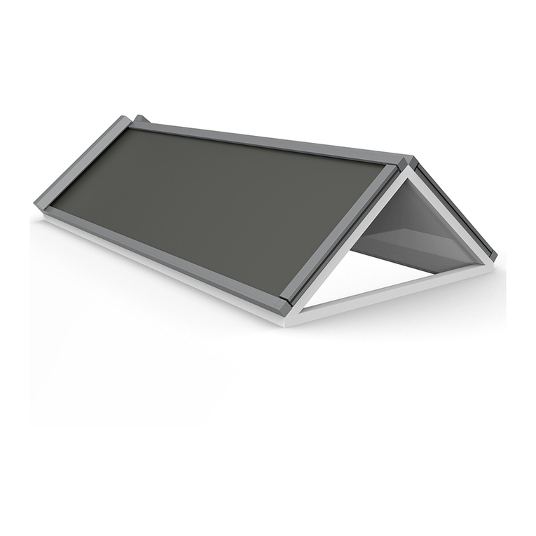
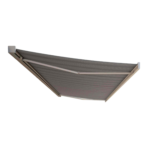
Harol US701 User manual

Assembly instructions
Pivot arm awnings
US701 - US702 - US715
art.nr. 41183

- 2 -V1-02-06
Assembly instructions pivot arm awnings US701 - US702 - US715
Contents
A. Introduction page 2
B. General warnings ! page 2
C. List of tools required page 3
D. Fitting instructions page 4
E. Electrical connections + motor page 11
F. Trouble-shooting page 15
G. Labels page 16
A. Introduction
The Harol - pivot arm awnings US701/US702 are cassette awnings. This means that, in a closed posi-
tion, fabric and roller tube are protected against weather conditions by the top board and the cover
cap. The closed case is a closed, all-protecting cassette.
The type US715 is a pivot arm awning without topboard and is therefore preferably mounted under a
balcony or other overhanging structure.
Pivot arm awnings have at least 2 projection arms. These arms are fitted in or before the opening
regardless of the fitting type of the box.
These assembly instructions explain the fitting of these systems step by step.
With this manual we confine ourselves to the instructions regarding the perfect installation of our sun
proctection. The contractor assumes full responsibility for the installation of the complete sun protec-
tion and all possible components added by this very contractor. Contractor is also held accountable for
the correct CE-labelling of the sun protection installed under his responsibility. This manual is meant
to be used by professionals only. It is not to be used by DIY-enthusiasts or apprentice fitters.
B. General warnings !
For a safe fitting, use and maintenance of this sun protection a number of precautions have to be
taken. For the safety of everyone concerned, please do take notice of the following general warnings !
- This manual is meant to be used by professionals only! It is not to be used bij DIY-enthusiasts or
apprentice fitters.
- Before you start ,please do read these instructions thoroughly.
- Be very careful and make sure of a solid footing whilst operating.
- Provide sufficent light in the fitting area. Dispose of obstacles and dirt. Make sure that, except for
the fitters, no other people are in the fitting area. Unauthorized people might be in the way or at risk
themselves.
- Whilst operating the system, you must be able to overlook the complete area and the whole of the
sun protection. There are a number of places where people might get injured. Especially watch the
following parts where people might risk getting jammed : the folding arms, the extension pole and
the casing.
- Electrical connections have to be made in accordance with the existing local norms and requirements.
The awning has been designed as a sun protection and for that reason it may not be
used as an all-weather protection. In case of heavy rain or wind the awning has to be
closed immediately. Therefore we recommend to use the sun protection in combina-
tion wth an automated wind/sun – control.

- 3 -V1-02-06
Assembly instructions pivot arm awnings US701 - US702 - US715
Guarantee and conditions :
- Harol has endeavered to design and assemble this sun protection in accordance with the ruling and
valid CE-norms. Nevertheless, feel free at any time to countercheck these interpretations with your
local national institute of normation.
- From this manual no rights can be derived. Technical alterations are possible without prior notifica-
tion.
- When dealing with larger projects, we do advise you to implement a full installation of 1 sun protec-
tion before starting with the installation of the rest of the sun protections. This way, an oversight or a
small mistake can be detected in its earliest and least expansive stadium.
- For our general conditions of sale: see pricelist.
Harol NV
Industriepark 3 - 3290 Diest
Belgium
Tel. +32 (0)13 38 01 11
Fax. +32 (0)13 31 48 03
E-mail: [email protected]
Internet: www.harol.com
C. List of tools required
- ladder(s)
- roller meter
- electric drill
- cross-head and flat-head screwdrivers
- set of open-ended or ring spanners
- ruler and pencil
- set of masonry drills Ø8mm – 12mm
- set of metal drills Ø 8mm – 10mm – 16mm
- level, waterhose, plumb line
- cord
- voltmeter or testing lamp 220 V
- test cable and switch

- 4 -V1-02-06
Assembly instructions pivot arm awnings US701 - US702 - US715
D. Assembly instructions US700
D.1. Open the cardboard wrapping
Control the width of the casing and measure the width of the opening and see whether they fully cor-
respond in the context of the fitting situation on hand.
Control the height of the system including the arms and measure the height of the opening. Look
whether they match in the context of the fitting situation.
D.2. Drilling the passage holes for the various operations
Measure the distance of the operational passage at the back of the casing and mark this distance on
the fitting surface.
Drill the hole of the operational passage through the window profile or through the wall:
For motor operation use a drill Ø10mm
For crank handle mono inside operation use a drill Ø16mm
For exterior worm gear operation with eye no hole needs to be drilled.
D.3. Control and division of the accessories
Take the bag with the accessories and divide the screws, plugs and washers equally among the number
of parts delivered. Apply the same rule to side consoles and/or wall brackets.
D.4. Fitting of the casing
Make sure the extension pole is pulled up against the casing. The casing is completely closed.
According to the local fitting situation, the box can be fitted in the following different ways:
1. Fitting of the box with side consoles (US701)
2. Fitting of the box with wall brackets (US702)
3. Fitting of the roller tube with wall consoles (US715)
Take care not to drill into the glass!
US701 US702 US715

- 5 -V1-02-06
Assembly instructions pivot arm awnings US701 - US702 - US715
Situation 1 – US701
Measure the holes to be drilled and do this on the side consoles of the box.
Transfer these marks to the wall or the fitting surface. Make sure these holes
are perfectly in line and use for this purpose waterhose and plumb line.
Do mark, if necessary, the holes for a possible wall bracket to be fitted into
the middle of the box and meant to prevent sagging of the box in the case
of great widths. Beware: the holes of this wall bracket are to be drilled higher
than those of the side consoles! Drill the attachment holes into the wall , use a
masonry drill Ø12mm. Introduce the S12 wall plugs into the holes.
Lift up the box and position the side consoles of the box in front of the holes. Then fix the side consoles
provisionally by means of the washers and the wood screws.
In the case of motor operation the motor cable has to be passed through the passage opening before
doing this.
Use a spirit level to make sure the box position is horizontal. Pull a cord from the two outer consoles in
order to control whether the box is hanging straight. Then tighten the screws firmly.
In case a wall bracket is to be used to support the middle of the box, then screw the wall bracket to the
bottom of the box, using the extra screw included (see fig.)
Make sure the holes are dust-free before pushing in the
plugs

- 6 -V1-02-06
Assembly instructions pivot arm awnings US701 - US702 - US715
Situation 2 – US702
Mark the holes to be drilled on the wall or the fitting surface by using one of the wall
brackets.The outer wall brackets have to be positioned as close as possible to the side
consoles of the box.
Make sure these holes are perfectly in line and use for this purpose waterhose and
plumb line. Do mark, if necessary, the holes for a possible wall bracket to be fitted
into the middle of the box and meant to prevent sagging of the box in the case of
great widths.
Drill the attachment holes into the wall , use a masonry drill Ø12mm.
Introduce the S12 wall plugs into the holes.
Now the wall brackets can be screwed to the wall. If necessary, adjust them to compensate for any
unevenness in the wall. Pull a cord from the two outer consoles in order to control whether the box is
hanging straight. Now tighten the screws firmly.Then lift up the box and attach it to the hooks of the
wall brackets.
In the case of motor operation the motor cable has to be passed through the passage opening before
doing this. Attach the bottom side of the box to the wall brackets, use the screws included (see fig.)
Ensure that the box is perfectly level. Pull a cord from the two outer consoles in order to control
whether the box is hanging straight.
Make sure the holes are dust-free before pushing in the
plugs

- 7 -V1-02-06
Assembly instructions pivot arm awnings US701 - US702 - US715
Situation 3 – US715
Slide the wall consoles, left and right side, including the open bearings, pro-
visionally onto the fabric roller. Measure the attachment holes to be drilled
on the wall consoles(frontal or sideways). Mark these holes on the wall or the
fitting surface. Make sure these holes are in a perfect horizontal line and use
for this purpose waterhose and plumb line.
Drill the attachment holes into the wall , use a masonry drill Ø12mm. Intro-
duce the S12 wall plugs into the holes.
Now the wall consoles can be screwed onto the fitting surface, using the washers and wood screws.
Take the fabric roller (including fabric and extension pole) and slide it with the open bearings into the
wall consoles. Attach the open bearers left and right in the wall consoles (see fig.)
In the case of motor operation the motor cable has to be passed through the passage opening before
doing this. Ensure that the fabric roller is perfectly level.
Beware of the quality of the wall, the fitting surface.
If the walls are made of cellular concrete, of soft or hollow brick, the correct type of
screw must be used, e.g. coach bolts, chemical anchoring, etc.. For this, take com-
prehensive advice from your supplier of attachment materials. The company Harol
accepts no responsibility for any attachment screws that come loose.
Make sure the holes are dust-free before pushing in the
plugs

- 8 -V1-02-06
Assembly instructions pivot arm awnings US701 - US702 - US715
Position elliptic holes in rear arm with VA/SA/WGA/GA
VA L = 300 mm (2 holes)
SA + WGA : L = 765 mm (2 holes)
GA 165 : L = 1600 mm (3 holes)
GA 195 : L = 1900 mm (3 holes)
3rd hole in the middle
30
9
6
6
6
6
L
9
101
9
3
11
25
12,5
22,5
4
33
48
5
9
74
35,5
5
9,5

- 9 -V1-02-06
Assembly instructions pivot arm awnings US701 - US702 - US715
D.5. Fitting of the arms:
Control the number of arms delivered. There must always be a left arm and a right arm, fitted to the
extremities of the box. The other arms have to be divided proportionally; if dealing with a coupled
awning, one arm must be fitted at the coupling
For the arms of the types VA, SA,WGA and GA: fit the arm assembly brackets for the extension pole to
the extremity of each arm
Take one arm and determine the exact fitting height. But beware! The height of the arms determines
the position of the extension pole. Ensure a correct linear positioning of the arms in correlation with
the extension pole because the extension pole closes the box!
Mark the attachment holes for the arms on the wall, do this for every arm and ensure that they are
perfectly level Use water hose and plumb line to control this.
When using the VAK-arms, the articulation points have to be shifted to the rear or to the front.
TABLE POSITION OF THE ARMS “X” with rod operation with eye “X” with mono-
command
“X” with electr.
or NTK*
SA/WGA 90 95 mm 70 mm 70 mm
VA/SA/WGA 105 95 mm 48 mm 48 mm
VA/SA/WGA 125 95 mm 48 mm 48 mm
VA/SA/WGA 140 95 mm 48 mm 48 mm
GA 165 95 mm 70 mm 70 mm
GA 195 95 mm 70 mm 70 mm
VA/SA/WGA 90 95 mm 48 mm 48 mm
VA/SA/WGA 105 95 mm 48 mm 48 mm
VA/SA/WGA 125 95 mm 48 mm 48 mm
VA/SA/WGA 140 95 mm 48 mm 48 mm
GA 165 95 mm 48 mm 48 mm
GA 195 95 mm 48 mm 48 mm
VAK 90 48 mm 48 mm 48 mm
VAK 105 48 mm 48 mm 48 mm
VAK 125 48 mm 48 mm 48 mm
VAK 140 48 mm 48 mm 48 mm
VA 90 95 mm 48 mm 48 mm
US701
US702
US701
US702
* NTK = opposite side of operation side

- 10 -V1-02-06
Assembly instructions pivot arm awnings US701 - US702 - US715
Fitting the fabric roller to the rear means a shift of 30mm. Fitting the fabric roller to the front means a
shift of 20mm.
Drill the attachment holes into the wall , use a masonry drill Ø8mm. Introduce the S8 wall plugs into
the holes.
Screw the arms tight to the wall (level). Attach the arm assembly brackets (which you have put on the
arms at a former stage) to the assembly strip in the extension pole.
Now the strings holding the arms together can be cut loose. Beware, the arms are now under consider-
able tension.
Now you can start operating the awning ( when dealing with fixed arms with chains, first remov e the
security clamp in the corner bracket of each arm)
D.6. Crank handle operation with eye - outdoors operation
In this case the screen box is supplied with an elongated plastic eye. To operate this system a crank
handle rod with a hook has to be used. Beware: always operate the system standing straight in front of
the rod exit, always use regular and avoid sudden movements. Don’t overstrain the system when you
feel a mechanical resistance.
D.7. Fitting of the cardan joint – indoors operation - For crank handle operation – mono
operation
Slide the included crank handle cardan joint and its 8x8mm square rod into the previously drilled
passage to the interior. Keep sliding until the rod grips into the opening of the gear box. Determine the
necessary length of the rod and saw it off, if necessary. The correct positioning of this bar guide is very
important and lateral contact between the rod and the wall of the cardan passage must be avoided at
all times. Make sure the rod is straightly positioned, not bent or askew. Drill the holes (Ø3.2mm) and
fasten the cardan joint to the fitting surface by means of screws.
Slide the plastified foldable crank handle over the round part of the cardan joint and use the splitpen
to connect the two items. Slide the security over the splitpen. Mark the place of the magnetic clamp
on the window profile or the wall and fix it by drilling . Make sure the metal part of the deployed crank
handle touches the magnetic clamp.
Detachable rod with rod coupling: the detachable folding rod has a funnel-shaped end. A splitpen is
slid on the globular free-hanging part of the cardan joint. A turning movement can attach or detach
the crank handle.
Make sure the holes are dust-free before pushing in the plugs
Watch out not to drill too close to the edge of bricks!
Great care must be taken there. The arms are under great stress. Before having taken
the necessary precautionary measures never remove the straps that keep the arms in
a closed position.

- 11 -V1-02-06
Assembly instructions pivot arm awnings US701 - US702 - US715
D.8. Coupled awnings (US701 / US702):
If the width of the awning exceeds 7 meters, the awning is delivered in two separate parts. Part 1 is
equipped with the drive and part 2 is the part to be coupled. The coupling takes place on the fitting
location..
Drill the attachment holes and fix the consoles to the wall as described earlier.
First take part 1, the part with the driving mecanism, and attach it to the wall. Then you provide this
part with all the coupling parts as there are: the connecting strip extension pole, the coupling pins of
the cover cap and the coupling pin of the fabric roller. Ensure that this part 1 is firmly attached and
cannot be moved. Then attach part 2 to the wall and slide it into part 1.
Beware! Do position the two awning parts in such a way, that the roller grooves are
perfectly in line.

- 12 -V1-02-06
Assembly instructions pivot arm awnings US701 - US702 - US715
E. Electrical connections + motor
Important remark: all electrical connections have to be made by a qualified fitter/electrician (see guar-
antee card 2.1.). Electrical fitting- and connection diagrams have to be applied in a correct way. The
electrical accessories used have to be conform the norms and/or demands in vigor.
E.1. Connection diagram of the single-pole switch
Four wires exit the motor: yellow-green (earth), blue (neutral), brown and black (up and down direc-
tion). Three wires exit the fuse box: yellow-green (earth), blue (neutral) and a phase wire. The phase
wire exiting the fuse box is to be connected to clamp L. If necessary, reverse the brown and black wire
of the motor within the switch, so that the arrows on the switch correspond to the raising and lower-
ing direction of the awning.
Connect the two blue wires in the housing of the switch by means of a cable. Do the same for the two
earth wires.
yellow / green
brown / black
brown / black
red blue

- 13 -V1-02-06
Assembly instructions pivot arm awnings US701 - US702 - US715
Connection and installation of the motor
Discreetly lead the motor cable to the switch. Connect the motor cable and the net wires to the single-
pole switch (see above). If necessary change the brown and the black wire according to the direction of
the arrows of the switch. If two or more motors have to be installed on one switch, you have to use one
or more relay boxes. For the connection of these see diagram RI2
Remark concerning the motor
If the motor is a standard type LT- or SLT- motor, you may proceed with this manual.
If the motor is an Orea RTS type or an Altus RTS type, please consult the fitting manual of these very
types.

- 14 -V1-02-06
Assembly instructions pivot arm awnings US701 - US702 - US715
E.2. Setting of the end switches of the motor
E.2.1. Roll-down direction - setting of the end position down
Allow the motor to run down. Make sure it stops in time,
before reaching the final down position. The end positions of
the motor haven’t been set at the factory , so the motor won’t
stop by itself.
Both adjusting buttons have been pushed in at the factory
(push them in if this is not the case)
Now let the motor run down until it reaches the desired end
position down. Then put the switch to its neutral
Press the white button (or yellow, depending on the building-in side) so that it rises slightly.
The end position down has been set.
E.2.2. Roll-up direction - setting of the end position up
LT - Motor
Remove the cover cap of the extension pole at the side of the motor in order to be able to reach the
adjusting buttons of the motor even when the extension pole has closed the box.
Now make the motor run up. Make sure it stops in time, just after the extension pole has closed the
box.
Then put the switch to its neutral
Press the white button (or yellow, depending on the building-in side) so that it rises slightly.
The end position up has been set
Both end positions have been set.
Let the motor run out for a couple of centimeters and put the cover cap of the extension pole back.
SLT – Motor
Make the motor run up. Make sure it stops in time, about 10 – 15 cm before reaching the box.
Then put the switch to its neutral
Press the blue button so that it rises slightly.
Let the motor run down again for another 10 – 15 cm, stop it and then close the awning .
After this you can hear the motor hum for a couple of seconds and then switch itself off.
The end position up has been set.
Both end positions have been set.
In case a new setting of the end positions should be necessary, the procedure can be repeated by
simply pushing in both adjusting buttons. In doing this you delete the existing end positions and the
setting can be repeated starting from point E.2.1.

- 15 -V1-02-06
Assembly instructions pivot arm awnings US701 - US702 - US715
E.3. Why use an RI2 relay box ?
If several motors are operated using the same switch, you must always use a relay box.
If relay boxes are not used, the integral limit switches will soon burn out due to the high inductive and
capacitive voltages which are mutually generated.
A useful tip: Always use the relay boxes and switches supplied by us for single operation of 2 or more
motors. The same applies to a ‘wind/sun automat’.

- 16 -V1-02-06
Assembly instructions pivot arm awnings US701 - US702 - US715
F. Trouble - shooting
F.1. Awning will not unroll or roll up:
- Internal switch of the motor has not been activated in any direction. Push in both adjusting buttons
and proceed with the setting of the end positions.
- Wire making poor contact after extending motor cable. Check connections.
- Motor has run hot. Leave 1/2 hour to cool.
- Faulty adjustment of limit switches on motor.
- No current supplied to switch. Check using voltmeter.
- Motor wrongly connected. Check the connection diagram.
F.2. Motor hums:
- Check whether everything is free to turn in both directions. Is anything blocked ?
- Capacitor in motor has blown (as a result of faulty connection of motor)
- Motor is wrongly connected: check correct connection of motor cables to the switch using the chart.
A phase wire (brown or black) has been transposed with neutral (blue). The motor will turn in one
direction, but in the other it will hum;
F.3. Motor does not stop in time:
- Faulty adjustment of limit switches (see p. …)
F.4. Bottom lath not straight:
- The arms are parallel, but not square to the casing. Check by applying Pythagoras’rule (3-4-5) or
measuring diagonals.
F.5. Fabric sticks during raising or lowering:
- Arms are out of square. See 4.
F.6. Fabrics not at the same heigth in rolled-down position
- Bad coupling of the fabric rolls. Turn one of the rolls for a ¼ or ½ turn
F.7. Direction of rotation of the motor does not match the arrows on the switch:
- Reverse the brown and black cables in the switch.
F.8. Blinds do not come to a stop and continue rolling up and down:
- Use a RI 2 of RI 3 relay box.
F.9. Automatic operation not working well:
- See fitting instruction for wind/sun automats.
G. Labels
If necessary, do apply warning labels.
Harol reserves the right to make changes at any time to the construction without having to inform the
client beforehand, and therefore without having to adapt existing installations.
This manual suits for next models
2
Other Harol Accessories manuals
Popular Accessories manuals by other brands
Tru-Test
Tru-Test WOW2 quick start guide
System Sensor
System Sensor 7351A Installation and maintenance instructions
Lightolier
Lightolier Lytecaster 1104ICR specification
Summit
Summit Raptor Series instructions
StarTech.com
StarTech.com ST122PROA Instruction guide
Lightolier
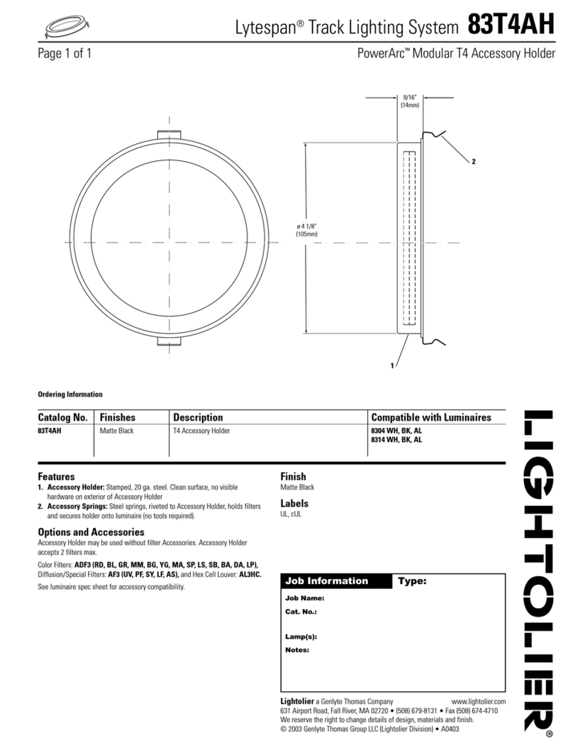
Lightolier Lytespan 83T4AH specification
