Harol TC110 User manual

Assembly instructions
Awnings
TC110 - TC120 - TC130
art.nr. 34581

- 2 -V4-10-10
Assembly instructions awnings TC110 - TC120 - TC130
A. Introduction
The TC100- range comprises the 3 awnings TC110, TC120 and TC130. The construction is caracterized
by the fact that extension pole, roller tube and the folding arms are fitted between or onto the two side
consoles. The standard type of this range allows a projection of 3 meters and a width of 5,5 meters.
B. General warnings !
For a safe fitting, use and maintenance of this sun protection a number of precautions have to be
taken. For the safety of everyone concerned, please do take notice of the following general warnings !
! This manual is meant to be used by professionals only! It is not to be used bij DIY-enthusiasts or
apprentice fitters.
! Before you start ,please do read these instructions thoroughly.
! The tightening of springs creates important powers. Be very careful and make sure of a solid footing
whilst operating.
! Provide sufficent light in the fitting area. Dispose of obtsacles and dirt. Make sure that, except for
the fitters, no other people are in the fitting area. Unauthorized people might be in the way or at risk
themselves.
! Whilst operating the system, you must be able to overlook the complete area and the whole of the
sun protection. There are a number of places where people might get injured. Especially watch the
following parts where people might risk to get jammed : the extension profile, the bench, the guide
rails and the casing.
! Our products must be installed so that all parts remain accessible at all times for maintenance and
eventual repairs. If this is not the case, Harol cannot be held responsible for any additional costs (f.e.
demolition activities, repairs to facades and interior walls) as a result of this.
C. List of accessories
• Ladder(s)
• Snap-off blade knife
• Measuring tape
• Drill
• Screwdriver and crosshead screwdriver
• Set open-ended spanners or ring spanners
• Pencil
• Set masonry drills
• Spirit level and water level tubing
• Voltmeter or test lamp 220 V
• Cord
• Set Allen keys
• Allen key 7 (special size)
The awning has been designed as a sun protection and for that reason it may not be
used as an all-weather protection. In case of heavy rain or wind the awning has to be
closed immediately. Therefore we recommend to use the sun protection in combina-
tion wth an automated wind/sun – control.
- 3 -V4-10-10
Assembly instructions awnings TC110 - TC120 - TC130
D. Assembly manual
D1. Opening the packaging:
Open the cardboard packaging. Be careful when using a knife to cut the straps. If the cardboard is slit
open carelessly, the paintwork can quite easily get scratched. You might even cut right through the
fabric. It is advisable to remove the plastic wrapping from the ends only, since during assembly, the
plastic protects the fabric from dirt.
D2. Checking the contents:
The TC100 is delivered, ready for assembly. They come with the necessary screws.
Carefully check the package contents and, before embarking on any of the assem-
bly activities, measure the main dimensions.
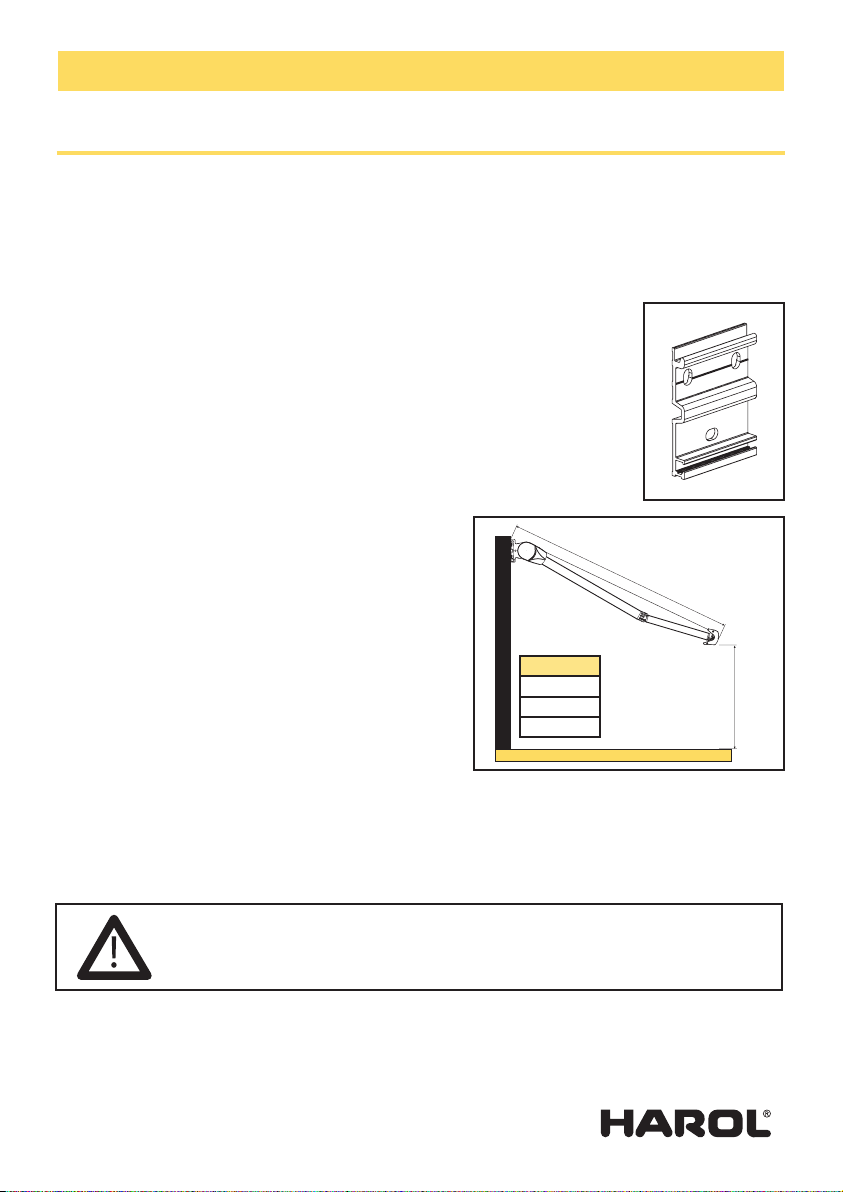
D3. Position of the assembly consoles:
For this type of awning it is important that the wall brackets are exactly behind
the exterior consoles. Measure the distance over the exterior consoles and mark
these on the wall. Position the brackets at the inside of these marks. Now mark the
location of the holes of the assembly consoles on the wall.
Take into account the following:
a. The awning must be positioned in such a way as to
leave the same distance between the left-hand and the
right-hand edge of the awning and the frame of the
window.
b. The consoles must be placed horizontally at right
angles to the pole. If necessary, use cord and level.
c. In order to allow for sufficient through height (C)
underneath the extension pole, it is essential to fit the
awning sufficient high up the wall.
The minimal angle of the awning is approximately 0
degrees and the maximum angle is 90 degrees, depen-
ding on the mounting type. A sloping clearance of 250
cm (A), corresponds to a minimal gradient of 0 cm and
maximum 260 cm, irrespective of the height of the extension pole.
Attention: a minimum incline of 15° is required to ensure efficient water run-off.
Now, drill the attachment holes for the wall screws. To select the correct means of attachment, consult
the tensile forces information sheet supplied with the box. This shows the tensile forces on the screws.
Also please contact your fastening materials supplier.
D4. Hooking in the awning:
Hold the awning at both ends and hook the side consoles in the assembly brackets. Check whether the
awning is centred.
A (mm)
1500
2000
2500
A = extension
C
If the walls are made of cellular concrete or hollow brick, the correct type of screw
must be used, e.g. coach bolts, etc. For this, take comprehensive advice from your sup-
plier of attachment materials. The company Harol accepts no responsibility for any
attachment screws that come loose.

- 4 -V4-10-10
Assembly instructions awnings TC110 - TC120 - TC130
The awning is now ready for further adjust-
ment. Now remove the plastic foil. Be careful not to damage
the paintwork.
Remark for the TC110:
for crank handle operation: remove the safety screws in the
gudgeon, left and right;
for motor operation: remove the safety screw in the gudgeon
at the opposite side of the motor; before
operating the awning.
D5. Adjusting the angle:
Unroll the awning and check the position of the angle (for
operating the awning: see point D6 and D7).
The awnings are delivered from the factory at a standard
angle (depending on the chosen mounting type) to
the horizontal. It will always be necessary to adjust the
awning to compensate for any unevenness in the wall,
even when the minimal sloping is acceptable.
The awning is provided with a tilting mechanism in the
side consoles. Remove the covers of the two side consoles
and unscrew the inner-hexagonal pointed screws, using
an Allen key 5. These screws prevent the awning from
blowing over. Now the angle can be adjusted with the
adjusting screw B at the bottom of the side console. This can be done by using an Allen key 6.
If adjusting screw B is turned to the right, the extension pole is raised, and if turned to the left, the
extension pole is lowered. When turning, support the arm ends. A screw will turn more easily if it is not
supporting the weight of the arm. This certainly will apply if the arms have to be raised.
To be sure that the pole is horizontal, stand in front of the middle of the awning.
Look over the extension pole towards the cover to ensure that both sections are parallel.
A
B
A
Slide screws C into the slot in the bottom of the assembly bracket and secure the
awning with the locking nuts. Repeat this operation with set screw D or hexagon
bolt D. Tighten the attachment screws firmly before operating the awning.
D
C
C
Mounting type 1 Mounting type 2 Mounting type 3 Mounting type 4

- 5 -V4-10-10
Assembly instructions awnings TC110 - TC120 - TC130
Once the angle is correct, both tilting mechanisms
must be securely tightened. To do this, tighten
both pointed screws ‘A’. Now, replace the covers
on the side consoles.
The TC100 adjusting mechanism will guarantee
continuous control of the awning. The system
is both accurate and simple to operate. It is
therefore essential to ensure that the awning is
perfectly horizontal. The correct setting of the
tilting mechanism will also facilitate the rest of
the assembly.
D6. Crank handle operation:
The standard operation device is a worm-screw
mechanism supplied with a transmission ratio
of 1 to 7. This mechanism requires no special
adjustment. Only a few factors must be taken into
account:
- The crank handle should be positioned as near as
possible in line with the eye-hoisting device while
turning.
- Always ensure that the fabric unwinds over the top of the roller
tube for this type of awning.
- Fully unroll the awning until the arms are almost in straight line,
at which point the arms have reached their maximum load-
bearing limit. However, if the roller tube is turned any further, the
fabric will be too slack. In that case make a few reverse turns until
the fabric is taut again.
D7. Electric motor:
For connecting or adjusting the electric motor, see point E.
Mounting type Angle (in °)
1 0 - 38
2 38 - 76
3 14 - 52
4 52 - 90
Mounting
type Angle Drop
1500 2000 2500 3000
10 0000
38 569 758 948 1137
238 569 758 948 1137
76 896 1195 1493 1792
314 223 298 372 447
52 728 970 1213 1455
452 728 970 1213 1455
90 923 1231 1539 1847
Tabel 1: Angle per mounting type
Table 2: angle in function of drop
(approaching values)

- 6 -V4-10-10
Assembly instructions awnings TC110 - TC120 - TC130
yellow / green
brown / black
brown / black
red blue
E. Connection of the single-pole switch and setting of the motor
E1-Single-pole switch
Firstly, connect the electric cable of the motor to a test cable.
Four wires exit the motor: yellow-green (earth), blue (neutral), brown and black (up- and down direc-
tion). Three wires exit the fuse box: yellow-green (earth), blue (neutral) and a phase wire.
Connect the wires according to the diagram. The phase wire exiting the fuse box is to be connected
to clamp P. If necessary, reverse the brown and black wire of the motor within the switch, so that the
arrows on the switch correspond to the raising and lowering direction of the awning.
Connect the two blue wires in the housing of the switch by means of a cable clamp. Do the same for the
two earth wires.

- 7 -V4-10-10
Assembly instructions awnings TC110 - TC120 - TC130
E2-Setting of the end switches of the motor
In principle the motor is already set at the factory, but it may
be necessary to change the setting.
For this proceed as follows:
For a LT-motor (TC110 – TC120):
First remove the yellow cap from the adjusting buttons.
Press in both buttons fully to against their stops so that they
remain a little deeper. The end settings are then fully removed in both directions.
Now allow the awning to roll out until the desired position is reached.
Note: never allow arms to go past their straightened position but stop them a little before. Then place
the switch to its neutral.
Press the white button (or yellow, depending on the building-in side) so that it rises slightly. Check the
roll-down direction of the fabric roll and establish which arrow on the motor corresponds with the
required rotational direction.
The buttons have the shape of a rounded arrow. The button, whose rounded side points at the rota-
tional direction of the fabric, is the button for adjusting that rotational direction. Push this adjusting
button once, so that it rises slightly. At that moment the roll-down direction is set.
Roll the blind up, until the extension pole touches the box.
Press the white button (or yellow, the other one, for the upper position) so that is rises slightly.
Replace the cover cap on the buttons.
The end switches of the motor are set now.
Important: If the awning unrolls too far without stopping automatically, turn the switch in the reverse
position and let the motor run for a while and then stop.
Push the corresponding adjusting button once again; in order to set the end switch to a neutral posi-
tion.
Let the motor run for a while and stop at the desired position. Push this last adjusting button once
again in order to set the new adjusting point.
Always check whether the motor is actually switched off when reaching its top position. A humming
sound after the extension pole is folded up, means that the motor is not adjusted properly. The motor
does not stop in time.
For a SLT-motor (TC130):
Remove the yellow cover cap from the buttons.
Press the buttons against their stops so that they remain a little deeper.
The end settings are fully removed in both directions.
Now allow the awning to roll out until the desired position is reached.
Note: never allow the arms to go past their straightened position but stop them a little before. Then
place the switch to its neutral position.
Press the white button (or yellow, depending on the building-in side) so that it rises slightly.
Then roll up the awning again and stop at a distance of 10 cm before the closing of the awning.

- 8 -V4-10-10
Assembly instructions awnings TC110 - TC120 - TC130
Then press the blue setting button.
Let the motor run down for 20 cm.
Close the awning completely. One can hear the motor hum for a few seconds, then it switches itself off.
Replace the cover cap on the buttons. The end switches of the motor are now set.
- 9 -V4-10-10
Assembly instructions awnings TC110 - TC120 - TC130
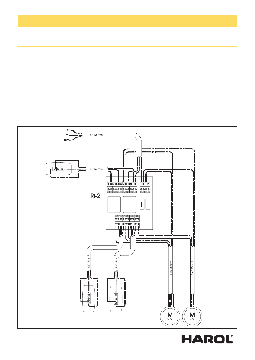
E3. Why use a MRI 2?
When the same switch operates different motors a relay box must always be used.
If relay boxes are not used, the built-in limit switches of the motor will very quickly burn due to the
high inductive and capacitive voltages that can be generated between them.
Good advice: always use the switches and relay boxes supplied by us.
yellow / green
brown / black
red
blue
yellow / green
blue

- 10 -V4-10-10
Assembly instructions awnings TC110 - TC120 - TC130
F. Fault-finding
Your Harol awnings are 100% checked before they leave the factory. It is therefore highly unlikely that
faults could be present whereby e.g. the motor does not work after assembly. Before contacting our
services it is advisable to first thoroughly check a number of points. These points below will probably
already provide the solution:
F1. The motor does not stop on time or it stops too early:
Adjust the settings of the motor properly according to the method described.
Make sure the SLT motor stops itself after only about 5 seconds after reaching the housing.
One can hear this by the throbbing noise of the motor that can still be heard for a short while in the
housing.
F2. The motor does not run in or out:
- Is there 230V at the switch?
Check this with a voltmeter or a test lamp.
- Check whether the motor has not thermally fused.
In this case it is sufficient to wait 15 minutes until the motor cools off.
- Check in the two directions whether the motor is in its extreme position.
- Check that the cable is not broken between the motor and the switch.
- Directly test the motor using a regulating cable.
F3. The end profile is deeper against the cover on one side than the other:
- This may be because the fabric has not been rolled up evenly.
- Check that the fabric on the top roller and the extension pole are exactly parallel.
- If necessary, adjust the fabrics on the pole.
- Fabrics are attached to the border of the extension pole by a plug. If the fabric continues to roll up
unevenly, add an extra piece of fabric to one of the side seams.
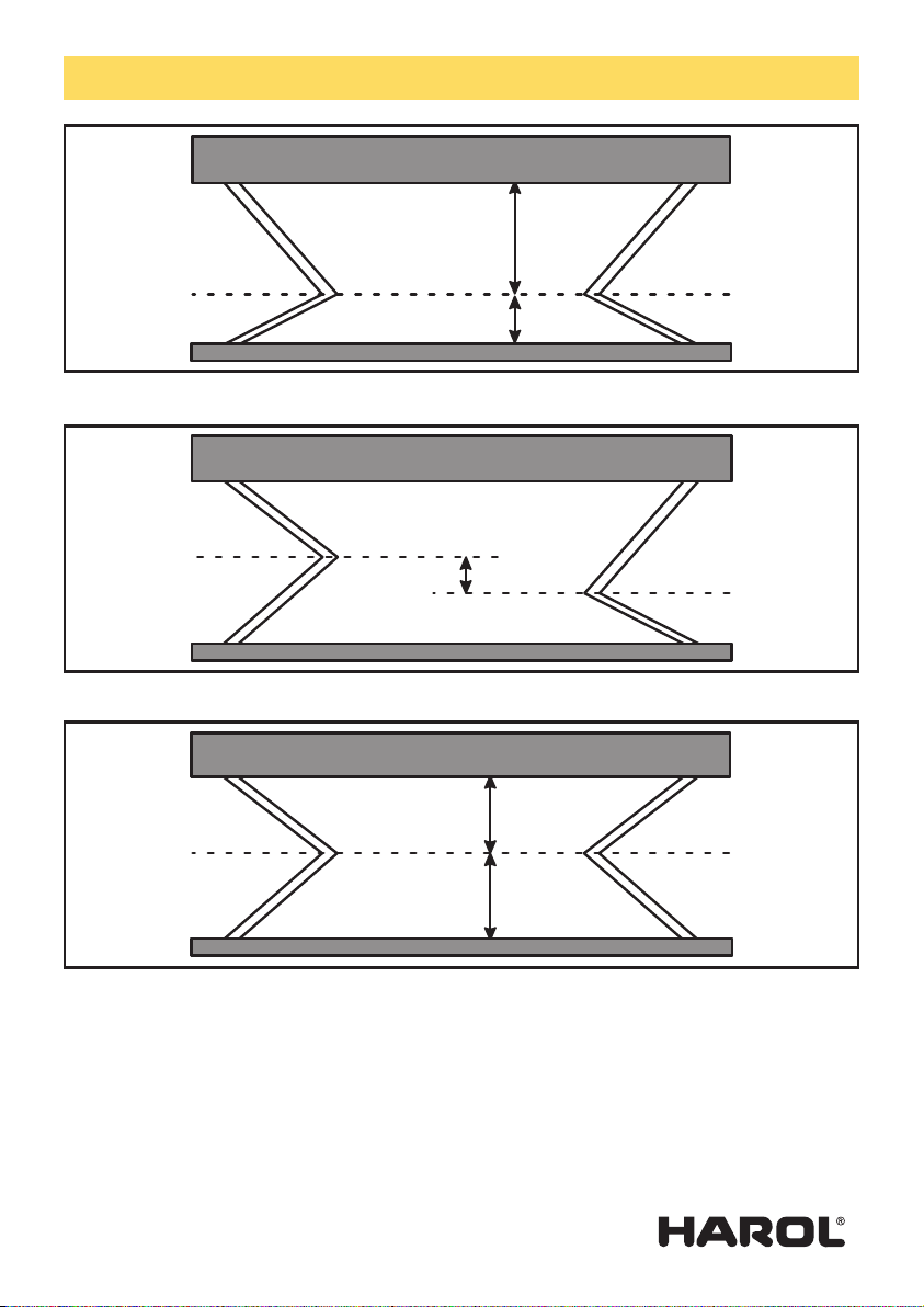
F4. The arms will not come in simultaneously:
- If the attachment points of the arms on the extension pole are not at a correct distance from each
other, one of the two arms will close slightly quicker than the other.
- Roll the fabric up almost fully but ensure that sufficient space is left to apply the Allen key to the
clamping plate on the inside of the extension pole.
- Roll the awning up a bit further and shift the arms, ensuring that the central articulated points of the
arms are in line.
- If necessary, shift the extension pole in its entirety and move it to the middle of the two lateral plates.
- Tighten the screws in the clamping plate with the Allen key.
F5. The awning makes a cracking sound:
Tighten the clamping screws of the side sonsoles very well.
Be careful: the arms are under constant tension and may slide in the groove.
- 11 -V4-10-10
Assembly instructions awnings TC110 - TC120 - TC130
Faulty: there is no symmetry, distance A does not correspond with distance B
Faulty: the articulated points are not in one line
Correct: the articulated points are in one line and distance A equals distance B
A
B
A
B

- 12 -V4-10-10
Assembly instructions awnings TC110 - TC120 - TC130
G. Mounting the side flaps
Please, remove the lateral fabric before closing the awning.
Harol reserves the right to make changes at any time to the construction without having to inform the
client beforehand, and therefore without having to adapt existing installations.
This manual suits for next models
2
Table of contents
Other Harol Accessories manuals


Popular Accessories manuals by other brands

eta
eta 2892A2 manual

Benewake
Benewake TF350 product manual

EuroLite
EuroLite AW-511 user manual

Simrad
Simrad PI BOTTOM CONTACT - QUICK REFERENCE GUIDE REV... Quick reference guide

Vanderbilt
Vanderbilt WMAG quick start guide

ATC Electrical & Mechanical
ATC Electrical & Mechanical atc.ie HANDSU Installation and operation manual


