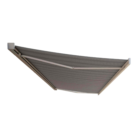
Harol TR850 User manual

Assembly instructions
Terrace awning
TR850
art.nr. 6837

- 2 -V3-10-10
Assembly instructions terrace awning TR850
Contents
A. Introduction page 2
B. General warnings ! page 2
C. List of tools required page 2
D. Fitting instructions page 3
E. Electrical connections + motor page 10
F. Finishing and maintenance page 13
G Trouble-shooting page 15
A. Introduction
The Harol TR850 terrace awning is an outside sun protection to be fitted on your terrace. This sun
protection blocks the sun rays and thereby protects your terrace against overheating.
These assembly instructions explain step by step the fitting of this system.
B. General warnings !
For a safe fitting, use and maintenance of this sun protection a number of precautions have to be
taken. For the safety of everyone concerned, please do take notice of the following general warnings !
- This manual is meant to be used by professionals only! It is not to be used bij DIY-enthusiasts or
apprentice fitters.
- Before you start ,please do read these instructions thoroughly.
- The tightening of springs creates important powers. Be very careful and make sure of a solid footing
whilst operating.
- Provide sufficent light in the fitting area. Dispose of obtsacles and dirt. Make sure that, except for
the fitters, no other people are in the fitting area. Unauthorized people might be in the way or at risk
themselves.
- Whilst operating the system, you must be able to overlook the complete area and the whole of the
sun protection. There are a number of places where people might get injured. Especially watch the
following parts where people might risk to get jammed : the extension profile, the bench, the guide
rails and the casing.
C. List of tools required
- ladder(s)
- electric drill
- masonry drills, 6 and 16 mm
- spanner, 19mm
- water hose or spirit level
- measuring rod
- chalk or felt pen
- cross-head and flat-head screwdrivers
- socket wrenches, 2,5 + 3 mm
- flat spanner 7 mm for cable clips
- hoist to set up cable and springs
- voltmeter or testing lamp 220V
- test cable to connect awning

- 3 -V3-10-10
Assembly instructions terrace awning TR850
D. Fitting instructions Terrace awning
The terrace awning is a sunblind which must
be fitted perfectly square and vertical. The
guide rails must be set up absolutely parallel
to one another. It is very important to work
with extreme accuracy and to make sure that
the base supports are solidly secured.
Where it is not possible to assemble on a
good concrete surface, it is advisable to lay
a foundation. We recommend a size of 30 x
30 x 60 cm for the concrete blocks. If desired,
light reinforcement may be included to pre-
vent the concrete from cracking (fig. 1).
If the differences in level are such that they
cannot be evened out, this must be stated
on your order form. The highest point of
the floor will then be taken as the reference
height for all other measurements.
The difference in level can be determined
precisely by using a water hose.
A spirit level is insufficiently pre-
cise in most cases to determine
levels (fig. 2).
A. Assembling the casing
The casing is secured to the wall
at each end by hinge pieces. Mark
the drilling holes on the walls.
Check the exact distance between
the fixing points. Proceed as
follows:
- First mark out the width of the
casing
- Then move in 41 mm form each end and mark a vertical line using a spirit level
- Then mark the desired height on this line so that the top edge of the casing matches the measure-
ment given on the order.
- As a check, measure the external dimension of the casing with respect to the floor using a plumb line.
- Draw a line on the ground at the required distance, perpendicular to the wall. The ground plates
for the base supports will fit inside this line in all cases. If necessary, calculate the squareness using
Pythagoras’rule: a² = b² + c² (see fig. “). The square- ness of this line is very important, and will guaran-
tee that the fabric rolls up properly in the future.
If all measurements are correct and there is sufficient room to set up the base supports, you can start
drilling the final holes for the wall fixings. The holes should be drilled using a 16 mm drill. Then insert
fig. 1: Foundation
concrete floor
floor tilling
foundation 30x30x60
40 cm
fig. 2: Difference in level
niveauverschil
level
extension
B
h
H

- 4 -V3-10-10
Assembly instructions terrace awning TR850
the plugs supplied in the wall. Remove the
lid of the casing, take hold of the casing
by the ends with the sections of guide rail
directed downwards, and with the hinge
points upwards (fig. 4).
Take care not to damage the fabric. Then
screw the casing firmly into position with the
hinge point against the wall.
Notes:
1. If necessary, the hinge pieces can always
be reserved on the cover so that the fixing
points are located beneath the casing (fig.
5).
2. For mounting on the ceiling a mounting
clip can be added if necessary.
3. For walls in poor condition it is recom-
mended to select the most suitable fixings
for each individual case (e.g. cotter bolts,
threaded rods, plugs, etc.). It may be neces-
sary to use other bolts or threaded rods. Sometimes adhesive bolts are
used.
4. The terrace awning can also be fitted directly using the guide rails. The
casing is then entirely borne by the support pins. The guides can then be
secured by means of angle sections. The mounting slots in the guide rails
allow clips to be fixed to the rails in various ways (fig. 6).
fig. 4 and 5fig. 6: mounting slots
fig. 3:
width box
41
41
60
B
C
A

- 5 -V3-10-10
Assembly instructions terrace awning TR850
B. Assembling the support rails
Now take the guide rails for the
sloping part of the sunblind (fig. 7).
Lay these rails in front of the sun-
blind, so that the end stop (A) fits
into the upper end of the rail with
the locking plates (E) on the inside
of the rails.
Check that the corner pieces are pro-
vided with a screw thread (B) to fix
the intermediate rollers.
Switch the guide rails about as nec-
essary until the rails lie in the right
place. Open the pack containing the rolled-up cable.
Check that there are still at least 3 turns on the cable reel.
If necessary add one turn. Unroll the cable, making sure
that no kinks are introduced into the cable. Then feed the
cables through the guide rails.
A useful aid in feeding the cables through the guide rails
while they are in a horizontal position is the 6 mm fabric
bar supplied. Feed the fabric bar lengthways through the
corner piece of the guide rail, over the internal pulley (fig.
8A). Let the fabric bar exit at the other end of the rail (B).
Slip the end of the cable (B) through the opening in the fabric bar. Now pull the cable forwards out of
the corner piece and draw it tight (A).
Remove the end stop in the guide rail by means of a screwdriver.
Now slide the necessary fixing plates into the grooves
provided in the guide rails.
Remove the locking plate in good time for this.
A plate ( C ) with a 10,5 mm hole and an M10 screw thread
must always be positioned at the side of the cast-iron
corner piece. If one or more intermediate rollers are to be
fitted, a plate (D) with two M10 screw threads must be
inserted for each intermediate roller.
If a storm bar is to be fitted, a short plate with a single
M10 screw thread should be mounted.
Now remove the short sections of guide rail inserted into the covers for
stiffening during transport (fig. 9).
Make sure the wheels do not fall off the runners.
If necessary, replace them in their proper position as shown in the draw-
ing (fig. 10).
The flat side of the wheels should always be on the inside, against the
fig. 7
fig. 8
fig. 9
fig. 10

- 6 -V3-10-10
Assembly instructions terrace awning TR850
runner. The conical side of the wheel should be on the outside (fig. 10).
Then insert the guide rails in the cover, along with the runners. To do this,
the casing must be tilted slightly on its fixing hinge.
Make sure that the cable runs directly from the cable reel into the open-
ing in the guide rail provided for it (fig 1). Draw the cable taut to ensure
this is the case.
Then insert the end of the cable under the small pulley so that it bears
completely on the innermost pulley.
While doing this, hold the other cover in the same position as the first to
avoid excessive twisting of the casing (fig 9). Then insert the second guide
rail into the cover. Make sure the rail fits properly against the back of the
cover.
IMPORTANT: In areas close to the sea or
in locations liable to severe corrosion, it
is recommended that the sawn edges of
all rails are covered with transparent sili-
cone cement. This will guarantee better
resistance to attack by the elements.
Re-fit the stop pieces in the slot in the
guide rail so that the runner can no
longer be pulled out of the rail. Drill
a hole through the guide rail in(to) the pin of the cover in the position
indicated and fix the cover with a parker screw (fig. 7).
Now remove from the packaging the guide rails for the vertical section.
The end which is cut off square forms the lower end.
Then fix the ground plates to the rails by means of two M10 screws.
Now insert the end of the cable through the guide rail from the top.
The cable must exit through a hole drilled in the back of the guide rail (fig. 13A).
Open the sliding cover for this using a socket wrench. Pull the cable
through the opening as far as possible, then insert the end back through
the guide rail towards the front (fig. 13B), beneath the pulley. Pull the
cable out fully.
Position the vertical supports so that the track for the runners is towards
the front. The corner piece fixing hole will then be on the inside. Then fix
a small plate in the slot.
The 10,5 mm hole in the strip must correspond with the 10,5 mm hole in
the guide rail (fig. 14).
If further connections to other rails are necessary, the necessary strips
must be provided here as well.
Position the two base supports in their places directly in front of the hori-
zontal guide rails, which should by lying on the ground.
fig. 11
fig. 12
fig. 13
fig. 14

- 7 -V3-10-10
Assembly instructions terrace awning TR850
Then take firm hold of the horizontal rails by the end with the corner
piece and bring this section immediately above the vertical bases. Now
press the corner piece into the vertical guide rail (Fig. 14). The guide rails
will now stand up by themselves.
Then remove the long intermediate rollers from the packaging. (N.B.:
there are two different sizes. There will always be a marked roller which
is 3 mm shorter than the others. This roller is fitted last, in the middle of
the corner).
Now fit intermediate rollers Nos. 1 and 2 on the drawing (fig. 15). The
fitting of these tubes must be carried out using a M10 x 20 screw for the
outer screws and M10 x 30 for the screws on the inside, which also pull
the corner piece tight.
Make sure that the upper edge of the tube is always level with the upper
edge of the guide rails. (The centre line of the tube may be out of align-
ment).
Then position the central roller on the corner with two M10 x 20 screws
at each end. If the tubes are fitted in the wrong order there may be dif-
ficulty tightening the bolts with a spanner.
If one or more intermediate rollers are to be fitted in the sloping part of
the guide rail, these are now dealt with. The spacing between these must
be kept even, and the position of the rollers must be identical at left and
right. Now take a spirit level and a ruler and position the base supports
perfectly vertical and at their correct distance from each other.
The distance between the two parallel base supports must match the
measurement at the top of the casing precise to the millimetre.
Re-check the squareness of the guide rails with respect to the wall.
If the differences in level were given when ordering the sunblind, the
tubes in the corner should now automatically be perfectly level. If a variation should, however, have
com about through a lack of precision in the measurements, this can be corrected by placing som pack-
ing material beneath the base supports.
This alignment of the guide rails is abso-
lutely necessary to avoid later problems
rolling up the long drops of fabric. Then
draw the drill holes on the floor (foun-
dations) through the holes in the base
supports, and screw the base supports
firm. Lay the remainder of the cable in the
outermost groove, in the middle of the pul-
leys in the corner piece (fig. 16).
Then pass the cable through below the
large wheel of the runner (fig 17-1) and
turn it through 180 degrees (2). Now insert
the end into the drop bar behind the small
wheel (3). Use a thread if necessary to help pull the cable through under the wheel of the runner.
Make a careful check that the cable is running properly on all the pulleys.
fig. 15
fig. 17
fig. 16

- 8 -V3-10-10
Assembly instructions terrace awning TR850
The tensioning system:
If the width of the terrace awning is between 350
and 500 cm, a simple pulley system can be used.
The two springs have a length of 1360 mm and
are located directly alongside each other inside
the drop bar. Inside the drop bar, at the distance
indicated, draw two marks. On these two marks,
position the plate which the springs will be
hooked to, in such a way that the centre line of
the pulley falls on the mark.
At one end (e.g. the right) pass the cable round
the pulley (fig. 17-4), and fix the end to the side
plate of the runner. Position the cable camp to
the inside of the drop bar (5).
Take a cable tensioning device, and clip this
firmly to the opposite end (side) of the guide
rails (fig. 19).
Then hook both springs to the right-hand plate,
and gently pull the cable taut. Check that the
cable on the right-hand section of the sun blind
is sitting well throughout. Start with the pulley
block, where no cables should be lying on top of each other. Then proceed along the length of the cable
until you are certain that it is sitting properly throughout.
Then hook the left-hand plate with a pulley to the springs. Fasten the claw of the cable tensioning
device around the plate.
Set the springs to tension (fig.19).
Pull using the cable tensioning device until the springs have been pulled to their correct tension (see
table). Now pass the left-hand cable around the left-hand pulley and fasten the end to the inside next
to the runner, using a cable clip.
Now slowly release the tension on the cable tensioning device.
Check that the left-hand cable of the sun blind is sitting properly throughout.
Carefully release the claw from the plate and remove the tensioning device.
The sunblind is now fully tensioned.
Check for a final time that the cables are still properly in place, before running the motor.
If the width of the terrace awning is between 200 and 350 mm a double pulley system is used. An extra
end pulley is mounted at each end of the drop bar.
The spring is also provided with a plate containing twin pulleys.
In this case, proceed in the same way as in the previous instructions, except that the cable runs round
the pulleys once extra.
This thus produces a doubling of force and halves the run of the spring.
BEWARE ! Now the sun protection is being put under tension.
Be careful and work safely!
fig. 18 (if width is less than 350 cm)
fig. 19

- 9 -V3-10-10
Assembly instructions terrace awning TR850
For the cable run see fig. 18.
Then place the plastic U-section supplied round the spring for protection (fig. 17B).
To prevent the spring from falling out during tensioning, short pieces of clip section can be places over
the spring as a temporary measure.
Leave these pieces of clip section in place temporarily during adjustment of the blind. In this way it is
very easy to check the position of the spring and the pulleys while the blind is unrolling.
The pulleys must always stay at a sufficient distance from the runners.
Then place the caps on the runners (fig. 17A).
fig. 20: spring diagram
680 mm spring, double 1360 mm spring ,single
EXTENSION
DISTANCE BETWEENROLLERS IN M

- 10 -V3-10-10
Assembly instructions terrace awning TR850
E. Electrical connections + motor
IMPORTANT : the electrical connections have to be made by a qualilfied installer/electrician (see guar-
antee card 2.1.) The diagrams for electrical fittings and connections have to be applied correctly and
all the electrical accessories used must be in accordance with the existing norms and requirements.
Connecting the single-pole switch and adjusting the motor
Connect the motor with a test cable first.
E.1. Single-pole switch
Connection diagram of a single-pole switch
There are four wires from the motor: yellow/green (earth), blue (neutral), brown and black (roll-up and
roll-down direction)
From the fuse box, there are three wires: yellow/green (earth), blue (neutral) and phase. Connect the
yellow / green
brown / black
brown / black
red blue
fig. 21: single-pole switch

- 11 -V3-10-10
Assembly instructions terrace awning TR850
wires as shown in the diagram. The phase wire from the fuse box should be connected to terminal L.
If necessary, reverse the brown and black leads from the motor in the switch so that the arrows on the
switch correspond to rolling up and unrolling the sun blind
The two earth wires are jointly connected by means of separate wire clips and the same thing goes for
the two neutral wires.
E.2. Setting of the motor limit switches
Important notice about the motor: if the motor is a standard
type SLT-motor, you can carry on using this manual. If the
motor is an Orea or Altus – motor, you must consult the
manual of this very type of motor.
E.2.1 Roll-down direction - setting of the end position down
Let the motor run down. Make sure it stops in time (before
reaching the end pulley for the lateral guide). The motor has
no settings and runs free.
Both control buttons at the motor head have been pushed in
(push them in if they haven’t been) Both buttons pushed in
means the motor won’t stop by itself.
Let the awning unroll until you have reached the desired
end position. Turn the switch of the test cable into its zero-
position. Now you push the white or the yellow button
on the motor head (depending on whether the motor is
built-in on the left or the right side), so that the button
pushed comes up.
The end position down is now set .
E.2.2. Roll-up direction - setting of the end position up
Let the awning roll up and stop it by using the limit
switch, at a distance of about 10 – 15cm before the casing.
Make sure the bottom lath runs up straight (check the
squareness of the guide rails with respect to the casing if
it doesn’t). Push the blue button at the motor head and
make it will come up.
Let the motor run down again (about 10 – 15 cm), stop
it and then roll up and close the awning. Having done
this the motor will hum on for a couple of seconds more
(this in order to anticipate a possible later stretch of the
fabric). The end switches and end positions of the motor
are set now.
In case you have to reset the motor, you can repeat the
procedure by pushing in both buttons at the motor head.
By doing this you delete the existing end settings and
you can proceed from E.2.1. on.
fig. 22
fig. 24: roll-up direction
fig. 23: roll-down direction

- 12 -V3-10-10
Assembly instructions terrace awning TR850
Why use an RI2 relay box ?
Terrace awnings consisting of several blinds are always driven by several motors. The motors can be
operated each using a separate switch. This allows each blind to be operated separately.
If, however, it is desired to operate the sun blind using a single switch, it is necessary to use a relay box.
If this is not done, the system will oscillate, and the high inductive and capacitative voltages created
will permanently burn out the built-in switches in the motor.
A good suggestion: Always use our relay box and switches supplied by us for single operation of 2 or
more motors. The same applies to a ‘wind/sun automat’.
yellow / green
brown / black
red
blue
yellow / green
blue
fig. 25: Relax box RI2

- 13 -V3-10-10
Assembly instructions terrace awning TR850
G. Finishing & Maintenance
G.1. Finishing
If the sun blind is to be fitted with a storm bar, lower the drop bar by
about 15 cm. Remove the closing plate at the upper end of the guide
rails. Then take the storm bar supplied out of its packaging and carefully
press the runner down into the guide rails. Make sure the magnets are
pointing forwards and are able to touch the metal plate. The blind will
then run through under the storm bar. Refit the closing plate in the cor-
rect position. Then place a stop in the middle of the inside of the guide
rails at both ends.
This stop must catch the projection on the runner, but must always allow
the drop bar to pass. If the motor has been fully adjusted, the lid of
the casing can be replaced. For wide sun blinds an extra support is
provided in the middle of the casing to fasten the lid.
- If a number of sun blinds are placed next to each other it is advis-
able to connect the vertical guide rails together. For this, use the
connecting strips supplied, and clip them to the rails immediately
below the corner.
- To prevent sideways movement of the guide rails measures must be
taken to ensure lateral stability. Try to make a connection to some
other element which will provide lateral support, such as a wall or a
diagonal stiffener on the ground.
- To avoid entry of rain, run-offs can also be fitted under the guide
rails. These run-offs should be fitted using small plates with an M6 screw thread and suspension
brackets.
Important notice: please do apply the following guidelines very strictly!
1. Fix the suspension brackets to the bottom of the lateral guides ( 1 per 1,2m ).
2. Drill a hole through the gutter and the brackets with a diam. 3mm. Fix the gutter to the side of the
brackets with a parker-screw
3. Position the clip of the drainpipe between the lateral guides ( these clips are not included and can be
purchased at the DIY ). For an optimal fastening of the outlet basket, the axis of the pipe has to have
a spacing of exactly 28 mm. ( see fig.)
4. Attach the drainpipe to the clips ( the drainpipe is not included and can be purchased at the DIY ).
5. Install the outlet basket with its outlet opening into the drainpipe. Fix the outlet basket to backside
of the lateral guides with a screw and a small plate into the slot holes.
fig. 26: Magnets
fig. 27: Stop

- 14 -V3-10-10
Assembly instructions terrace awning TR850
G.2. Maintenance
- The terrace awning is in the first instance a sun blind. With a suitable slope, i.e. 15 to 20 degrees,
the sun blind can also be used to provide shelter from moderate rain. It goes without saying that a
sudden large quantity of water on the blind will cause sagging if the water is not drained off. Sag-
ging may cause a large quantity of water to collect, which will lead to overloading of the blind. If it
is desired to leave the terrace awning permanently in the open position, it is necessary to provide a
sufficient slope (i.e. at least 27 cm drop per 100 cm).
- The blind will be at its greatest tension when it is at its full extent. It is therefore recommended to roll
out the blind fully during moderate wind. It is only in this position that the fabric will be fully taut.
- As a result of the dirt which is always in the air, the fabric and the rails will certainly become dirty
after a certain time. These particles of dirt may settle in the groove ahead of the runners. Accumula-
tions of dirt in the grooves will cause the mechanism to run unevenly, which may eventually result in
the whole blind seizing up. The guide rails should be regularly cleaned for this reason.
- Turning parts exposed to the atmosphere will be sure to run dry after a certain time and start squeak-
ing. For this reason, pulleys should be regularly lubricated. Make sure regular lubrication is supplied
to the pulleys in the base, and to those in the corner pieces.
- Also, at least once a year, lubricate the bearings of the axle in the casing.
- If the blind has become wet, it is better to let it dry off than to roll it up immediately.
If the awning and the fabric have been caught by rain, it is better to let the fabric dry up before rolling
it up. Rolled up wet fabric stays wet for a long time therefore risks rotting or getting mouldy.
1
5
53
4 4
2
2
1
fig. 28: Gutter

- 15 -V3-10-10
Assembly instructions terrace awning TR850
H. Fault-finding
1. Blind will not unroll or roll up:
- Wire making poor contact after extending motor cable. Check connections.
- Motor has run hot. Leave 1/2 hour to cool.
- Faulty adjustment of limit switches on motor.
- No current supplied to switch. Check using voltmeter.
- Motor wrongly connected.
2. Motor hums:
- Check whether everything is free to turn in both directions. Is anything blocked ? (cable ?)
- Capacitor in motor has blown (as a result of faulty connection of motor)
- Motor is wrongly connected: check correct connection of motor cables to the switch using the chart.
A phase wire (brown or black) has been transposed with neutral (blue). The motor will turn in one
direction, but in the other it will hum;
3. Motor does not stop in time:
- Faulty adjustment of limit switches (see p. …)
4. Internal flap not straight:
- Guide rails are parallel, but not square to the casing. Check by applying Pythagoras’rule (3-4-5) or
measuring diagonals.
5. Internal flap is not straight against the casing when rolled up:
- see point 4 above.
6. Fabric sticks during raising or lowering:
- Steel cable not running properly over pulleys.
- Spring blocked
7. Fabric not taut at bottom:
- Guide rails are not straight with respect to the casing.
- Steel cable sticking somewhere
- Spring not under sufficient tension.
8. Direction of rotation of the motor does not match the arrows on the switch:
- Reverse the brown and black cables in the switch.
9. Blinds do not come to a stop and continue rolling up and down:
- Use a RI 2 of RI 3 relay box.
10. Sun blind makes abnormal noise when unrolling and cable creaks
- Wind the first few turns neatly on the pulley of the take-up roller.
11. Automatic operation not working well:
- See fitting instruction for wind/sun automats.

This manual suits for next models
1
Table of contents
Other Harol Accessories manuals
Popular Accessories manuals by other brands

Extreme Networks
Extreme Networks BlackDiamond 6800 user guide

Panasonic
Panasonic HL-C211F instruction manual

SICK
SICK CQF16 operating instructions

Sygonix
Sygonix 2612693 operating instructions
Delta Electronics
Delta Electronics DVP08ST11N Specification sheet
Aztech Technologies Pte Ltd.
Aztech Technologies Pte Ltd. Kyla user guide
Orno
Orno OR-DB-YK-117 instructions
nano sensorics
nano sensorics VOCLESS Operation and installation manual
Reiner
Reiner jetStamp 790 MSL operating instructions
Campingaz
Campingaz Powerbox Plus 24L Instructions for use
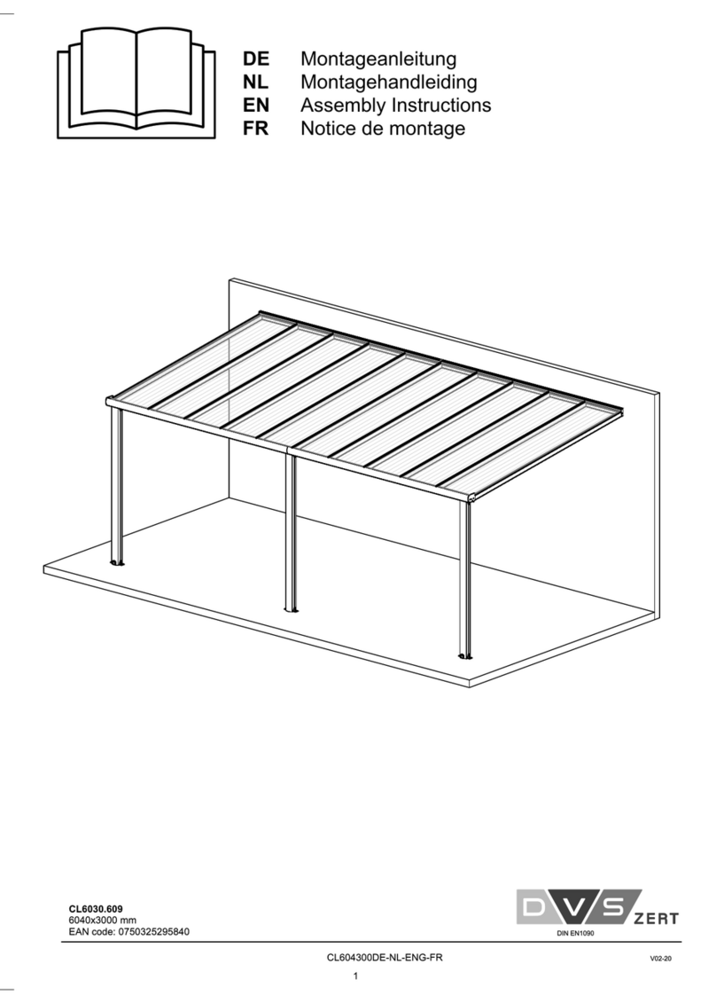
DVS
DVS CL6030.609 Assembly instructions

Contours
Contours CURVE SIT & BOOGIE ZY039 manual
