Harol SL400 User manual

INSTALLATION &
OPERATION MANUAL
WIND AND SUN SCREEN
SL400
Art. no. 49013
SUN PROTECTIONSHUTTERSDOORS

InstallatIon and operatIon Manual for WInd and sun screen sl400
09/12 | 2
TABLE OF CONTENTS
1. INTRODUCTION 3
2. GENERAL WARNINGS 3
3. LIST OF TOOLS REQUIRED 4
4. INSTALLATION STEPS 5
4.1. Checking and opening the packaging 5
4.2. Checking the contents 5
4.3. Checking the dimensions 5
4.4. Fabric opening left or right 5
4.5. Mounting height of the wall brackets 6
4.6. Alignment of the wall brackets 7
4.7. Optional mounting of the box (A2638) 7
4.8. Hooking up the box 7
4.9. Installation of the supporting system 7
4.10. Optional installation of a supporting system for wall or railing assembly (A2639) 8
4.11. Fine-tuning of the handgrip height and the supporting system 8
5. DISMANTLING 9
6. PUTTING INTO OPERATION AND HANDOVER 9
6.1. Opening the screen 9
6.2. Closing the screen 9
6.3. Handover to the customer 9
7. USER INFO 10
7.1. Basic information 10
7.2. Safety instructions 10
7.3. Terms of use 11
7.4. Maintenance 11
8. TROUBLESHOOTING 12
9. GENERAL INFO ON FABRICS 12
Appendices: CE certificate of conformity
Service log
Handover form installer
Handover form customer

InstallatIon and operatIon Manual for WInd and sun screen sl400
09/12 | 3
1. INTRODUCTION
The SL400 is a wind and sun screen. The screen consists of a box with roll-up system, a
fabric, a pull rod and a supporting system mounted at drop distance from the box. At the
top, the fabric can be either straight or oblique with a maximum angle of 15° and depending
on the length of the drop reinforced with boning. This drop can vary from a minimum of 1
metre up to a maximum of 4 metres.
This manual starts with a step-by-step description of the installation instructions of the
SL400 for installers. This is followed by information concerning the use and maintenance
of the screen for the end user. The last pages consist of the handover forms which the
installer can use to handover the SL400 to the end user.
2. GENERAL WARNINGS
A number of precautions must be taken for the safe installation, operation and maintenance
of the SL400. Please take note of the following warnings for the safety of everyone
concerned!
!Please read these instructions carefully before starting with the installation.
!The screen must be fitted or mounted in accordance with local requirements and
standards. All work must be carried out by a trained and experienced member of
sta from recognized companies, and never by “do-it-yourself” fitters or apprentices.
!Always proceed with caution. Ensure that you have a robust footing.
!Make sure there is adequate lighting in the assembly space. Remove obstacles and
dirt. Ensure that no other persons except the installers are present. Unauthorized
persons can get in the way or be at risk during the installation.
!There is a lot of tension on the fabric of the wind and sun screen, due to the
integrated coiled spring located in the fabric roll. Always take the necessary care
when assembling or dismantling the screen.
!The screen must be kept clearly in view at all times during installation and operation.
Persons in the vicinity may be at risk of injury.
!Our products must be installed in such a way that all parts remain accessible at
all times for maintenance and repairs. If this is not the case, Harol cannot be held
responsible for any additional costs (e.g. demolition work, repairs to exterior or
interior walls) which may result from this.
The SL400 has been designed for use as a wind and sun screen and as such
must not be used for all-weather protection. During heavy rain or wind the
screen must be retracted immediately.

InstallatIon and operatIon Manual for WInd and sun screen sl400
09/12 | 4
Guarantee, terms and conditions
• Harol has endeavoured to design and manufacture the SL400 in compliance with
the current CE standards. Always check that our version complies with your own
national standards.
• No rights can be derived from these instructions whatsoever. Technical modifications
are reserved without written notification.
• All parts supplied are intended for this specific screen. Adding dierent parts may
have a negative impact on the safety of your awning. The warranty is void if parts are
added or changed without first consulting the supplier.
• For large projects we strongly advise you to first fit 1 complete awning before fitting
the remaining awnings. This will help detect any potential faults early on and enable
these to be remedied at the lowest possible cost.
• For our general terms and conditions of sale: see price list.
• Make sure the box can always be opened so the mechanical parts inside can be
reached easily. If this requirement is not respected, Harol cannot be held responsible
for the cost of demolition work or any paint work or wallpapering.
Harol NV
Industriepark 3 – 3290 Diest
Belgium
+32 (0)13 38 01 11
+32 (0)13 31 48 03
info@harol.be
www.harol.com
3. LIST OF TOOLS REQUIRED
• Ladder(s)
• Box cutter
• Tape measure
• Pencil or felt pen
• Spirit level, plumb line or hose level
• Cord
• Drill and set of stone drills
• Cross-head and flat-head screwdrivers
• Set of open-ended and ring spanners
• Set of Allen keys

InstallatIon and operatIon Manual for WInd and sun screen sl400
09/12 | 5
4. INSTALLATION STEPS
4.1. Checking and opening the packaging
First check the packaging for any external damage. Next open the cardboard packaging.
Be careful when cutting the straps with a knife. Careless opening of the box may result in
damage to the paint. It is recommended to remove the plastic film only from the ends. The
plastic provides good protection during installation.
4.2. Checking the contents
The SL400 is delivered ready for installation and includes the required screws. Check the
contents of the package and check that the box has been painted in the requested colour.
Check also that the supporting system is present, together with the guarantee card and
the table with tensile forces on screws. Screws for installation on the existing mounting
surface are not included.
4.3. Checking the dimensions
Measure the length of the box of the SL400. This should be 50 mm smaller than the specified
ordered length! The drop can only be checked after the screen has been mounted.
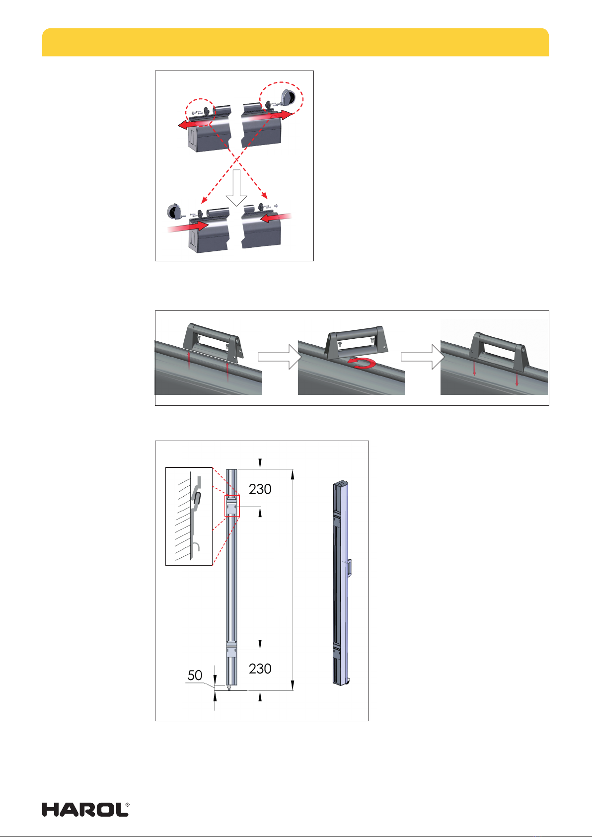
4.4. Fabric opening left or right
left right
Before starting with the installation, check that the fabric
opening is facing the correct side as specified in the order. If
upon closer inspection you decide that you want the other
fabric opening, then this can only be done on-site with the
straight fabric configuration.
Changing the fabric opening must always be carried out with the
screen closed, and the 3 steps below must be closely followed.
1. Unscrew the suspension bracket from the housing or box, rotate the suspension
bracket 180° and then reinstall it in the same place using the nut and bolt.
InstallatIon and operatIon Manual for WInd and sun screen sl400
09/12 | 6
2. Detach the wheel from the pull rod; this is done
by unscrewing the pin with an SW12 spanner.
Unscrew the cover on the other side of the pull rod
with an SW5 Allen key. Switch around the wheel
and cover and tighten the screws again.
3. Loosen the handgrip by unscrewing two flush mount screws with an SW4 Allen
key, rotate the handgrip 180° and refasten it at the correct height. This height is
determined by the support pin or supporting system.
4.5. Mounting height of the wall brackets
The height of the mounting brackets
on the wall must match the distance
between the brackets on the box
of the SL400. The housing of the
wind and sun screen must be placed
vertically at 50 mm above the
ground, to accommodate the wheel
at the bottom of the pull rod.
The choice of fastening materials
for the attachment of the brackets
depends greatly on the mounting
surface. For walls made of cellular
concrete blocks or soft/hollow bricks
it is necessary to use appropriate
fastening materials such as expansion
bolts, chemical anchors etc. The
installer is responsible for selecting
the best method. Harol accepts no
responsibility for fasteners that do
not hold securely.
HEIGHT

InstallatIon and operatIon Manual for WInd and sun screen sl400
09/12 | 7
4.6. Alignment of the wall brackets
The two wall brackets must be plumb and level. Any irregularities in the mounting surface
must be compensated. Take the time to make sure the screen is positioned perfectly vertically.
If the mounting surface is of poor quality, we recommend ordering additional brackets. Also
check the distance between the brackets and then tighten all the screws. The mounted
screen is now ready for further adjustment and alignment of the supporting system.
4.7. Optional mounting of the box (A2638)
Instead of mounting the wall brackets directly on to the wall,
it is also an option to use a wall console for each wall bracket.
Here too the choice of fastening materials depends largely
on the mounting surface and must be assessed by the fitter.
The mounting height of the wall consoles must match the
distance between the brackets on the box of the SL400.
Once again, it is very important that the wall consoles are
aligned correctly.
4.8. Hooking up the box
A damping rubber is placed over each wall bracket. Next, the
SL400 can be hoisted over the brackets and pressed down
so the screen is suciently protected and secure.
Two people are required to attach heavier screens.
4.9. Installation of the supporting system
A supporting system should be installed at drop distance from the box in order to keep the
screen in the open position. This supporting system is for hooking up the pull rod.
There are various ways to do this:
• Floor assembly (A2642): A support pin with ground support plate are anchored on
to the floor, optionally either a concrete anchor (option A2640) or a ground anchor
(A2641) can be used.
• Wall assembly (A2644): A wall mounting block must first be mounted to the wall
using the appropriate fastening materials. Next a short support is fastened to the
mounting block.
• Railing assembly (A2643): A wall mounting block must first be mounted to the
railing using the appropriate fastening materials. Next a support pin is fastened to
the mounting block.

InstallatIon and operatIon Manual for WInd and sun screen sl400
09/12 | 8
Always make sure that the supporting system is mounted perfectly vertically and is correctly
anchored. The height of the pull rod depends on the height of the screen. For the locking
system the rule of thumb is to have it positioned at half the height.
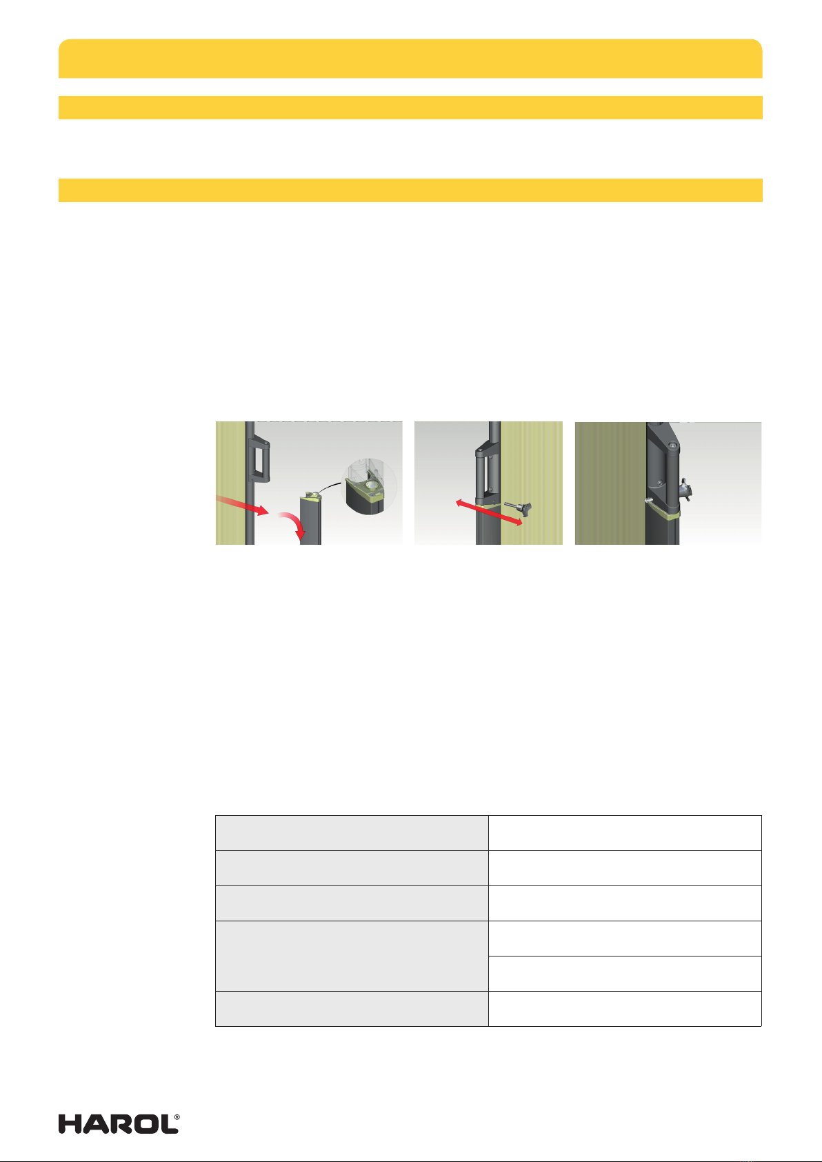
4.10. Optional installation of a supporting system for wall or railing assembly (A2639)
Instead of mounting the supporting system directly
with wall or railing mounted systems, it can also be
mounted to the wall using a wall console for columns
(option A2639). In this case the wall mounting block
must be removed, so the supporting system can
be secured to the wall console with the three bolts
supplied. Depending on the mounting surface, the
fitter must choose a particular option for securing
the console to the wall.
The mounting height of the wall console needs to
be such that the top of the cover & lock plate of the
supporting system are at the same height as the bottom
of the handgrip of the pull rod. Correct alignment of
the wall console is also very important here.
4.11. Fine-tuning of the handgrip height and the supporting system
If the bottom of the handgrip of the pull rod does not grip into the cover & lock plate, then
this can be resolved by lowering or raising the handgrip. This is done by gently unscrewing
two countersunk screws, repositioning the handgrip and then tightening the screws again.
(A2641)
(A2640)
Floor assembly
(A2642)
Wall assembly
(A2644)
Railing assembly
(A2643)
InstallatIon and operatIon Manual for WInd and sun screen sl400
09/12 | 9
5. DISMANTLING
Always close the screen before lifting it and removing it from the brackets.
6. PUTTING INTO OPERATION AND HANDOVER
6.1. Opening the screen
• To open the screen use the pull rod and handgrip. Always make sure that the wheel
at the bottom of the pull rod rolls over the floor! This ensures a smooth and even
extension of the screen.
• Once the screen has reached the support, lift the handgrip slightly upwards and on
to the locking system.
• Then press the handgrip downwards and give it a brief tug to ensure it has properly
engaged with the locking system.
• Finally, to prevent the screen from suddenly disengaging, a safety lock is pushed
through the hole in the handgrip. In order to be able to carry out this action, you
must first press down the pin on the button.
6.2. Closing the screen
To close the screen, follow the reverse procedure for opening the screen (see F.1.).
Never suddenly let go of the fabric and the pull rod! Closing the SL400 in an uncontrolled
manner can damage the fabric and result in personal injuries!
6.3. Handover to the customer
After assembling and testing the screen, clean up the workplace, take the packaging away
with you and hand this installation and operating manual to the user. Do not forget to
complete the handover forms on the last pages.
To make it easier for us to respond to any questions or to provide you with information
regarding this SL400 in the future, please make sure the installation details below are
completed by the installer.
Product name: Wind and sun screen SL400
HAROL order number:
Installation date:
Handover:
from:
to:
Installer’s signature:

InstallatIon and operatIon Manual for WInd and sun screen sl400
09/12 | 10
7. USER INFO
7.1. Basic information
Before operating the SL400, you need to have sucient knowledge of the product. The
contents of this manual is a sound basis for a smooth, continuous operation and a long
service life of this product.
Also, for the sake of personal safety, it is important to follow these instructions. Failure to
follow these instructions relieves the manufacturer of all liability.
Keep this installation and operation manual handy for future reference. Should the SL400
be handed over to a third party, then this manual must also be supplied to the new owner.
7.2. Safety instructions
A number of precautions must be taken for the safe operation and maintenance of the
SL400. Installation, maintenance or repair of the wind and sun screen by anyone other
than a recognized fitter can be a safety hazard or cause injury. For the safety of everyone
concerned, please take note of the instructions, warnings and directions below! If in doubt,
always contact your supplier. Always take care when using the sun screen!
!Please read this manual carefully before operation or maintenance.
!Installation, maintenance and repairs must only be carried out by a qualified and
experienced technician!
!Malfunctions, which can impair the safety, must be reported and repaired
immediately.
!The product may only be operated by persons who have been instructed by the
installer about the correct mode of operation. It is strictly forbidden to allow children
to operate the SL400! They may put themselves at risk while operating the screen.
!When opening and closing the screen, always keep the SL400 in sight and make
sure that there are no persons (children!) or obstacles within its range of movement.
!The safety lock must always be engaged when the screen is open, to prevent it from
unexpectedly retracting.
!Watch out for hands/fingers when hooking up the pull rod to the system, as well as
when closing the screen. Danger of pinching!
!If work is being carried out in the vicinity of the screen, then make sure it is always
closed.
!Ensure that the sun screen is regularly inspected and maintained..
DANGER! BECAUSE OF THE INTEGRATED SPRING SYSTEM, THERE IS ALWAYS
TENSION ON THE SL400. FOR THIS REASON ALL REPAIRS OR DISMANTLING
MUST BE CARRIED OUT BY PROFESSIONALLY TRAINED AND QUALIFIED
STAFF. ALWAYS TAKE CARE WHEN USING THIS SUN SCREEN!

InstallatIon and operatIon Manual for WInd and sun screen sl400
09/12 | 11
7.3. Terms of use
• The SL400 serves mainly as a protection against wind and sun or for additional
privacy. It must never be used for all-weather-protection.
• The sun screen should never be exposed to wind loads that are greater than 27
km/h or greater than 20 km/h if a ground anchor is being used. Also the fastening
materials used for the mounting surface play an important part. The manufacturer
accepts no responsibility for damage caused by excessive wind.
• Never unroll the screen in rain, snow or freezing weather conditions. This may cause
damage.
• If the fabric of the wind and sun screen becomes damp or wet, then it must be dried
as quickly as possible while unrolled. Otherwise there is a risk of stains and mould
appearing or damage to the fabric or the seams.
• The screen must be rolled up during the night and when no one is present.
• Always avoid any accidental loads on the SL400. This can lead to damage or
defects.
• A screen that is not in perfect condition must be repaired immediately.
• Only OEM replacement parts may be used for repairs.
• The manufacturer is not responsible for damage resulting from improper use.
7.4. Maintenance
To guarantee trouble-free use of the SL400 it is prudent to regularly maintain and inspect
the screen, at least once a year. Check for signs of wear or damage to the fabric or frame.
In the case of wear or damage, your installer is the designated person to carry out these
repairs.
You can carry out small maintenance and inspection jobs as described below. Never use
a high-pressure cleaner!
Maintaining the fabric:
• The screen fabric has been treated with a special dirt-repellent product, which slows
down the process of dirt build-up.
• Use a soft brush to clean dust from the dry sun screen fabric.
• For watery stains first moisten the fabric and then rub with a clean cloth. Only use
detergents such as soap or other chemical products in very exceptional situations.
• For finger or oil stains, use a clean cloth with a drop of soft neutral washing-up liquid
and subsequently use plenty of water to rinse. Always avoid using trichloretane.
• After cleaning the fabric always allow it to dry thoroughly.
Maintaining the frame:
• The supporting system, the pull rod and the external box must be cleaned regularly
with tepid water and a neutral soap such as car shampoo, and rinsed thoroughly with
tap water (at least 2x a year).
• It is emphatically not recommended to use corrosive or aggressive products,
scouring pads or other abrasives.
InstallatIon and operatIon Manual for WInd and sun screen sl400
09/12 | 12
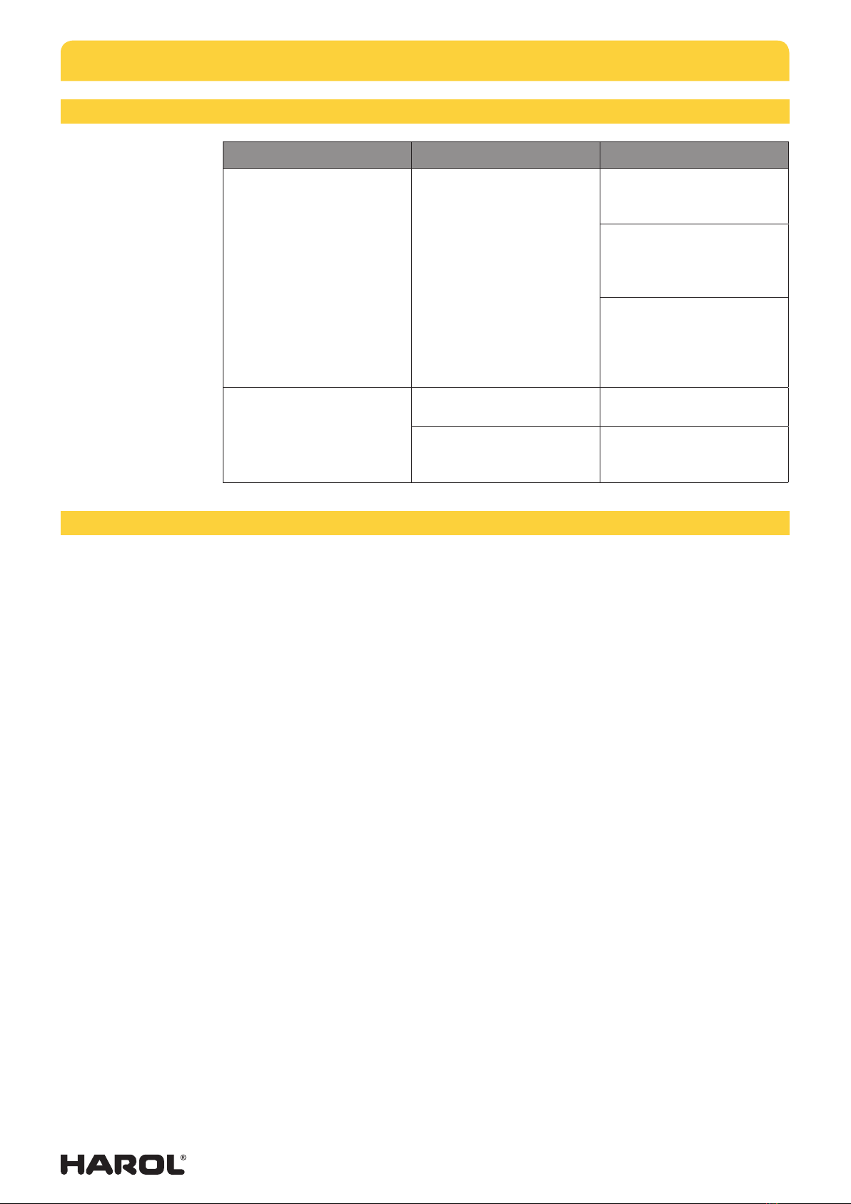
8. TROUBLESHOOTING
NATURE OF THE FAULT CAUSE SOLUTION
Pull rod does not fit tightly
against the box in the
closed position.
The fabric does not roll up
evenly.
Pull out the pull rod to fully
extend the fabric and then
roll it up again.
Keep more tension on the
pull rod and fabric whilst
extending it and rolling it
up.
The wheel no longer turns
freely, making it necessary
to hold the pull rod higher
above the ground whilst
rolling up the screen.
Fabric does not roll up
evenly or one end is rolled
loosely.
The height of the handgrip
is incorrect.
Adjust the position of the
handgrip.
The height of the housing
is incorrect.
Slightly adjust the height of
the assembly brackets for
the box.
9. GENERAL INFO ON FABRICS
The fabric collection consists of acrylic fabrics and the Soltis range (86, 92 or 96), which
can be selected from the collection folders.
The same fabric may have a dierent surface and slight variations in colour or design cannot
be completely eliminated.
When working with a much larger drop, rows of fabric are needed and consequently creasing
may occur. There is also a greater risk of the fabric becoming slack because of the weight
of the fabric, however, this will not aect the functioning of the screen in any way.
Where the fabric is attached to the fabric roll, stripes may appear for each rotation around
the roll.
The above-mentioned cases are not errors, but phenomena which are the result of technical
factors. These can never give rise to complaints, or be a reason for demanding another
fabric or for obtaining a discount!

09/12 | 13
CE-Gelijkvormigheidsverklaring
Machinerichtlijn 2006/42/EC
Wij, Harol NV, verklaren geheel onder eigen verantwoordelijkheid dat de producten
waarop deze verklaring betrekking heeft, in overeenstemming zijn met de volgende norm of
ander(e) normatie(f)(ve) document(en)
Deze verklaring is enkel geldig indien de installateur de installatie heeft uitgevoerd
geheel volgens de voorschriften van de fabricant en
volgens de normen die van kracht zijn op de installatie.
België, Diest, 1 maart 2011
Screens, type SC700, SC800 en
uitvalschermen, type US701, US702 en wind-zonnescherm SL400
EN 13561
Gelezen en goedgekeurd,
de installateur,
Stempel:
Datum plaatsing:
Industrieterrein 1/3 - I.Z. Webbekom 1025| 3290 Diest | België
tel. +32 13 38 01 11 | fax +32 13 31 48 03
de fabrikant,
Harol NV
vertegenwoordigd door
Dhr. Jan De Lobel
kwaliteitsmanager
CE-Conformity declaration
Relevant EC Directives pertaining to machines 2006/42/EC
We, Harol NV, declare fully on our own responsibility that the products
related to this declaration, are conform to the following agreed standard or
other normative document(s).
This declaration is only valid if the installer has executed the installation
fully conform the conditions of the manufacturer and
conform the agreed standards pertaining to the installation.
Belgium, Diest, 1 March 2012
Screens, type SC700, SC800, SC900 and drop arm awnings, type
US701, US702 and lateral screen SL400
EN 13561
Seen and approved,
the installer,
Stamp:
Date of installation:
Industrieterrein 1/3 - I.Z. Webbekom 1025 | 3290 Diest | Belgium
tel. +32 13 38 01 11 | fax +32 13 31 48 03
the manufacturer,
Harol NV
represented by
Mr Jan De Lobel
quality manager

09/12 | 14
Technical assistance:
(name, address, telephone number)
SERVICE-LOG BOOK
This proof book contains technical references and records of installation, maintenance, repairs and alterations carried out and must be made
available for any inspections by authorised bodies.
Customer: (name, address and reference persoon)
Description of the solar protection: (model, type)
Identification number: (clear reference of the solar protection)
Location: (address)
Fabric: (collection, quality)
Power supply: (voltage and input)
Type of operation: (hold-to-run, impulse, automatic)
Installer: (name, address, telephone number)
Date of installation: (day, month, year)
List of components installed (drive unit, control and safety devices)
The technical features and performances of the components listed below are documented in the relevant installation manuals and/or on the label
on the component itself.
Operation: (type, serial number)
Motor: (type, serial number)
Relay box: (type, serial number)
Wind-sun automatic: (type, serial number)
Switch: (type, serial number)
Remote control: (type, serial number)
Other domotics: (type, serial number)
Miscellany: (type, serial number)
Warning of residual risks and of foreseeable improper use
Inform with signs attached to the risk points of the product and/or with written instructions to be given and explained to the user of the solar
protection, or whoever is responsible, about the existing risks and the foreseeable improper use.

09/12 | 15
Date Description of work
(Installation, start-up, adjustments, check on
safety devices, repairs, alterations, ...)
Installer’s
signature
Customer’s
signature

✂
Order no :
Client :
Address :
Tel. :
Date :
Installer :
Address :
Tel. :
FORM OF TRANSFER
Confirmation of transfer
The solar protection has been mounted without visible defects, and according to
the agreements made with the seller and/or the installer*.
If not, what are the remarks :
* If the client is content with the formal control and bring the solar protection into use, he/she is supposed to have accepted it.
The client has been familiarized with the operation of the product, according to
the prescriptions by means of the manual for the consumer.
The solar protection may be used in following weather conditions:
Wind (*):
* Indicate the allowable wind resistance class in function of the location, mounting and mounting-surface.
Rain : ◊ not permitted ◊ permitted under the supervision of the user ◊ permitted
Danger of frost : ◊ not permitted
The following documents are transfered to the user :
Manual for the consumer :
Assembly instructions :
Manual of the manufacturer of motors, switches and electronical control :
Others :
◊ Yes ◊ No
◊ Yes ◊ No
◊ Yes ◊ No
◊ Yes ◊ No
◊ Yes ◊ No
Signature installer Signature client
Assembly made by :
Name : From time : Till time : Number of
hours
until a wind resistance class of 3 = wind-force 6 Bft. = 49 km/h max. permitted SC800 SC900
until a wind resistance class of 2 = wind-force 5 Bft. = 35 km/h max. permitted SC800 SC900 SC700 US701
/ US702
until a wind resistance class of 1 = wind-force 4 Bft. = 27 km/h max. permitted SC800 SC900 SC700 US701
/ US702 SL400
until a wind resistance class of 0 = wind-force ≤ 3 Bft. = ≤ 20 km/h max. permitted SC800 SC900 SC700 US701
/ US702 SL400
specimen installer
✂
Order no :
Client :
Address :
Tel. :
Date :
Installer :
Address :
Tel. :
FORM OF TRANSFER
Confirmation of transfer
The solar protection has been mounted without visible defects, and according to
the agreements made with the seller and/or the installer*.
If not, what are the remarks :
* If the client is content with the formal control and bring the solar protection into use, he/she is supposed to have accepted it.
The client has been familiarized with the operation of the product, according to
the prescriptions by means of the manual for the consumer.
The solar protection may be used in following weather conditions:
Wind (*):
* Indicate the allowable wind resistance class in function of the location, mounting and mounting-surface.
Rain : ◊ not permitted ◊ permitted under the supervision of the user ◊ permitted
Danger of frost : ◊ not permitted
The following documents are transfered to the user :
Manual for the consumer :
Assembly instructions :
Manual of the manufacturer of motors, switches and electronical control :
Others :
◊ Yes ◊ No
◊ Yes ◊ No
◊ Yes ◊ No
◊ Yes ◊ No
◊ Yes ◊ No
Signature installer Signature client
Assembly made by :
Name : From time : Till time : Number of
hours
until a wind resistance class of 3 = wind-force 6 Bft. = 49 km/h max. permitted SC800 SC900
until a wind resistance class of 2 = wind-force 5 Bft. = 35 km/h max. permitted SC800 SC900 SC700 US701
/ US702
until a wind resistance class of 1 = wind-force 4 Bft. = 27 km/h max. permitted SC800 SC900 SC700 US701
/ US702 SL400
until a wind resistance class of 0 = wind-force ≤ 3 Bft. = ≤ 20 km/h max. permitted SC800 SC900 SC700 US701
/ US702 SL400
specimen client
This manual suits for next models
1
Table of contents
Other Harol Accessories manuals


